2019 MERCEDES-BENZ GLS SUV ESP
[x] Cancel search: ESPPage 157 of 729
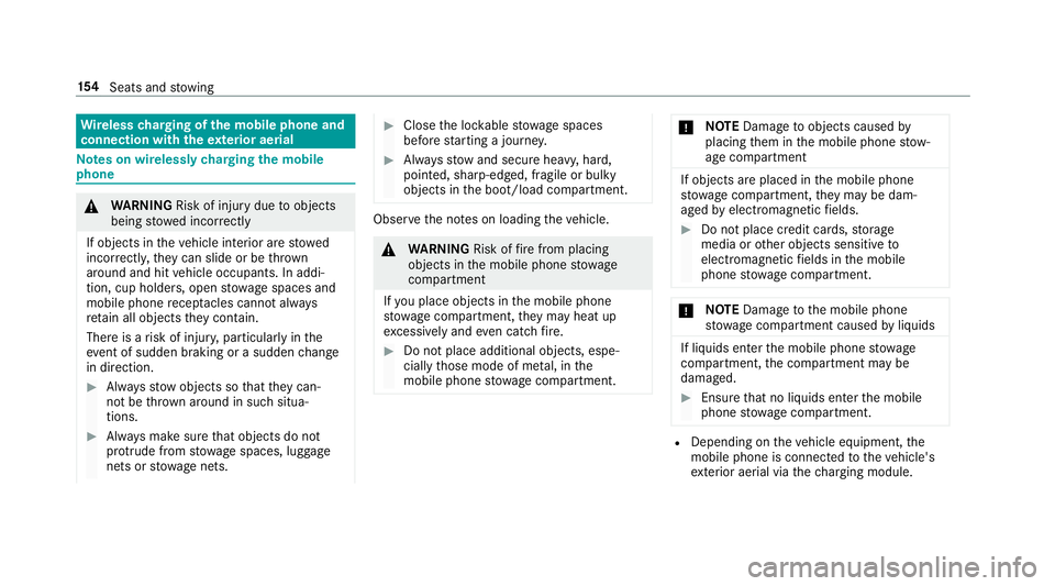
Wire
lesscharging of the mobile phone and
connection with theex terior aerial Note
s on wirelessly charging the mobile
phone &
WARNING Risk of inju rydue toobjects
being stowed incor rectly
If objects in theve hicle interior are stowed
incor rectly, they can slide or be thrown
around and hit vehicle occupants. In addi‐
tion, cup holders, open stowage spaces and
mobile phone recep tacles cannot al ways
re tain all objects they contain.
The reis a risk of injur y,particularly in the
ev ent of sudden braking or a sudden change
in direction. #
Alw aysstow objects so that they can‐
not be throw n around in su chsitua‐
tions. #
Alw ays make sure that objects do not
pr otru de from stowage spaces, luggage
nets or stowage nets. #
Close the loc kable stow age spaces
before starting a journe y. #
Alw aysstow and secure heavy, hard,
poin ted, sharp-edged, fragile or bulky
objects in the boot/load compartment. Obser
vethe no tes on loading theve hicle. &
WARNING Risk offire from placing
objects in the mobile phone stowage
compartment
If yo u place objects in the mobile phone
stow age compartment, they may heat up
exc essively and even catch fire. #
Do not place additional objects, espe‐
cially those mode of me tal, in the
mobile phone stowage compartment. *
NO
TEDama getoobjects caused by
placing them in the mobile phone stow‐
age compartment If objects are placed in
the mobile phone
stow age compartment, they may be dam‐
aged byelectromagnetic fields. #
Do not place credit cards, storage
media or other objects sensitive to
electromagnetic fields in the mobile
phone stowage compartment. *
NO
TEDama getothe mobile phone
stow age compartment caused byliquids If liquids enter
the mobile phone stowage
compartment, the compartment may be
damaged. #
Ensure that no liquids enter the mobile
phone stowage compartment. R
Depending on theve hicle equipment, the
mobile phone is connected totheve hicle's
ex terior aerial via thech arging module. 15 4
Seats and stowing
Page 159 of 729
#
Place the mobile phone as close tothe
centre of mat 1as possible wi th the display
fa cing up wards.
When the indicator lamp lights up, the mobile
phone is being charge d. Fi
tting/ removing the floormats &
WARNING Risk of accident due to
objects in the driver's foot we ll
Objects in the driver's foot we ll may impede
pedal tr avel or block a depressed pedal.
This jeopardises the operating and road
saf ety of theve hicle. #
Stow all objects in theve hicle securely
so that they cannot getinto the driver's
fo ot we ll. #
Alw aysfit th efloor mats securely and
as prescribed in order toensure that
th ere is alw ays suf ficient room forthe
pedals. #
Do not use loose floor mats and do not
place floor mats on top of one ano ther. #
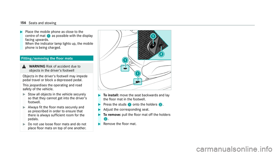
Toinstall: movethe seat backwards and lay
th efloor mat in thefo ot we ll. #
Press thest uds 1onto the holders 2. #
Adjust the cor responding seat. #
Toremo ve: pull thefloor mat off the holders
2. #
Remo vethefloor mat. 15 6
Seats and stowing
Page 160 of 729
Exterior lighting
Note
s onchanging the lights when driving
abroad Ve
hicles with static LED headlamps: It is not
necessa ryto change the headlamps. The legal
re qu irements are also met in countries in which
traf fic drives on theot her side of thero ad.
Ve hicles with Intelligent Light Sy stem: The
headlamps are automatically swit ched over
when theve hicle enters countries where people
drive on theot her side of thero ad. Information about lighting sy
stems and your
re sponsibility The
various lighting sy stems of theve hicle are
only aids. The driver of theve hicle is responsible
fo r cor rect vehicle illumination in accordance
with the pr evailing light and visibility conditions,
legal requirements and traf fic situation. Light switch
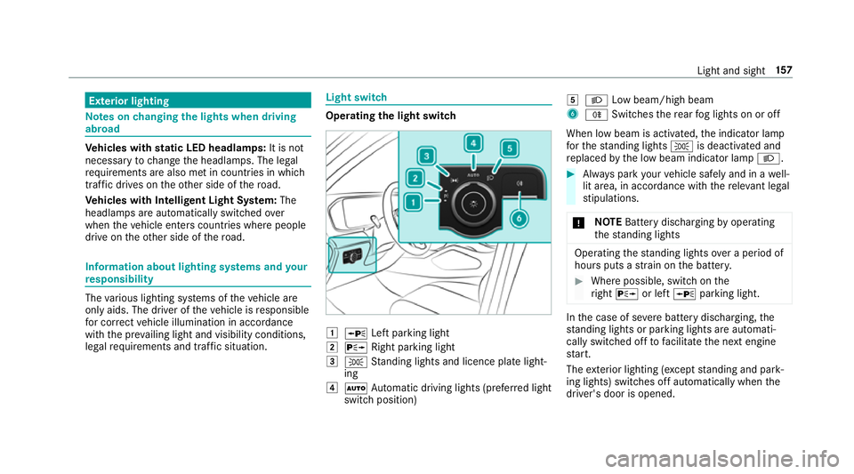
Ope
rating the light switch 1
W Left pa rking light
2 X Right parking light
3 T Standing lights and licence plate light‐
ing
4 Ã Automatic driving lights (prefer red light
switch position) 5
L Low beam/high beam
6 R Switches there ar fog lights on or off
When low beam is activated, the indicator lamp
fo rth est anding lights Tis deactivated and
re placed bythe low beam indicator lamp L. #
Alw ays park your vehicle safely and in a well-
lit area, in accordance with there leva nt le gal
st ipulations.
* NO
TEBattery discharging byoperating
th est anding lights Operating
thest anding lights over a period of
hours puts a stra in on the batter y. #
Where possible, switch on the
ri ght X or left Wparking light. In
the case of se vere battery discharging, the
st anding lights or parking lights are automati‐
cally swit ched off tofacilitate the next engine
st art.
The exterior lighting (e xcept standing and park‐
ing lights) swit ches off automatically when the
driver's door is opened. Light and sight
157
Page 161 of 729
R
Obser vethe no tes on sur round lighting
(/ page 163).
Au tomatic driving lights
The standing lights, dipped beam and daytime
ru nning lights are switched on au tomatically
depending on the ignition status, whe ther the
engine is running and on the light conditions. &
WARNING Risk of accident when the
dipped beam is switched off in poor visi‐
bility
When the light switch is set toà ,the
dipped beam may not be switched on auto‐
matically if there is fog, snow or other causes
of poor visibility such as spr ay.#
In such cases, turn the light switch to
L . The automatic driving lights are only an aid.
Yo u
are responsible forve hicle lighting. Switching
there ar fog lights on or off
Re quirements:
R The light switch is in the L orà posi‐
tion. #
Press the R button.
Please obser vethe count ry-specific la wsonthe
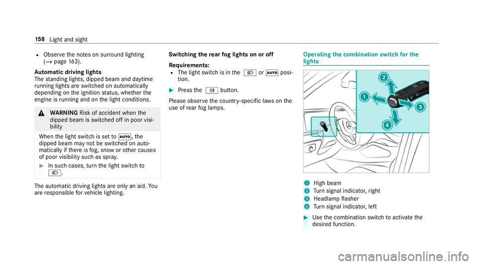
use of rear fog lamps. Operating
the combination switch for the
lights 1
High beam
2 Turn signal indicator, right
3 Headlamp flasher
4 Turn signal indicator, left #
Use the combination switch toactivate the
desired function. 15 8
Light and sight
Page 162 of 729
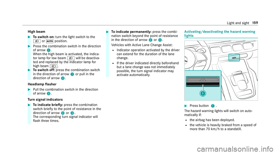
High beam
#
Toswitch on: turnthe light switch tothe
L orà position. #
Press the combination switch in the direction
of ar row1.
When the high beam is activated, the indica‐
to r lamp for low beam Lwill be deactiva‐
te d and replaced bythe indicator lamp for
high beam K. #
Toswitch off: pressthe combination switch
in the direction of ar row1or pull in the
direction of ar row3.
Headlamp flasher #
Pull the combination switch in the direction
of ar row3.
Tu rn signal indicators #
Toindicate briefl y:press the combination
switch briefly tothe point of resis tance in the
direction of ar row2or4.
The cor responding turn signal indicator will
fl ash thre e times. #
Toindicate permanentl y:press the combi‐
nation switch be yond the point of resis tance
in the direction of ar row2or4.
Ve hicles with Active Lane Change Assi st:
R Indicator operation activated bythe driver
can extend forth e duration of the lane
ch ange.
R Ifth e driver indicated directly beforehand
but a lane change was not immediately
possible, the turn signal indicator may
activate automaticall y. Ac
tivating/deactivating the hazard warning
lights #
Press button 1.
The hazard warning lights will switch on auto‐
matically if:
R the airbag has been deplo yed.
R theve hicle is heavily braked from a speed of
more than 70 km/h toast andstill. Light and sight
15 9
Page 165 of 729
Multimedia sy
stem:
4 © 5
Settings 5
Lights
5 Intell. Light System #
Activate or deacti vate the function. Ad
aptive Highbeam Assist Plus Ad
aptive Highbeam Assist Plus function &
WARNING Risk of accident despi te
Ad aptive Highbeam Assist Plus
Ad aptive Highbeam Assist Plus does not rec‐
ognise thefo llowing road users:
R Road users without lights, e.g. pedes‐
trians
R Road users with poor lighting, e.g.
cyclists
R Road users whose lighting is obstructed,
e.g. bya bar rier
On very rare occasions, Adaptive Highbeam
Assist Plus may failto recognise other road
users that ha velights, or may recognise
th em too late. In
this, or in similar situations, the automatic
main beam will not be deactivated or will be
activated despite the presence of other road
users. #
Alw ays obser vethe tra ffic carefully and
switch off the main beam in good time. Ad
aptive Highbeam Assist Plus cannot take into
account road, weather or traf fic conditions.
De tection may be restricted in thefo llowing
cases:
R in poor visibilit y,e.g. fog, heavy rain or snow
R ifth ere is dirt on the sensors or the sensors
are obscured
Ad aptive Highbeam Assist Plus is on lyan aid.
Yo u are responsible for adju sting theve hicle's
lighting tothe pr evailing light, visibility and traf‐
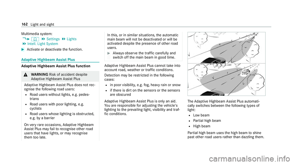
fi c conditions. The
Adaptive Highbeam Assist Plus automati‐
cally swit ches between thefo llowing types of
light:
R Low beam
R Partial high beam
R High beam
Pa rtial high beam uses the high beam toshine
past other road users rath er than dazzling them. 16 2
Light and sight
Page 174 of 729
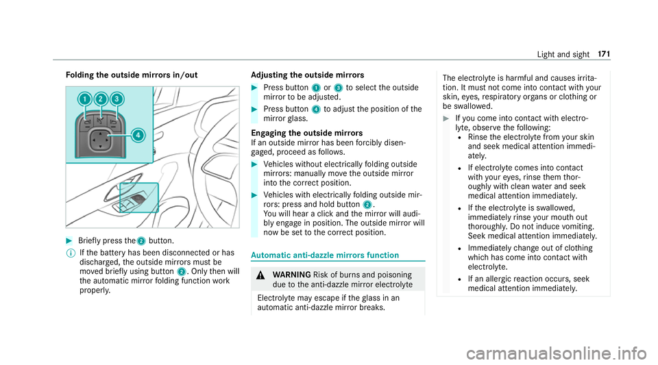
Fo
lding the outside mir rors in/out #
Brief lypress the2 button.
% Ifth e battery has been disconnected or has
dischar ged, the outside mir rors must be
mo ved briefly using button 2. Onlythen will
th e automatic mir rorfo lding function work
proper ly. Ad
justing the outside mir rors #
Press button 1or3 toselect the outside
mir rorto be adjus ted. #
Press button 4toadjust the position of the
mir rorgl ass.
Engaging the outside mir rors
If an outside mir ror has been forc ibly disen‐
ga ge d, proceed as follo ws. #
Vehicles without electrically folding outside
mir rors: manually mo vethe outside mir ror
into the cor rect position. #
Vehicles with electrically folding outside mir‐
ro rs: press and hold button 2.
Yo u will hear a click and the mir ror will audi‐
bly engage in position. The outside mir ror will
now be set tothe cor rect position. Au
tomatic anti-dazzle mir rors function &
WARNING Risk of bu rns and poisoning
due tothe anti-dazzle mir ror electrolyte
Electrolyte may escape if theglass in an
automatic anti-dazzle mir ror breaks. The electrolyte is harmful and causes ir
rita‐
tion. It mu stnot come into contact wi thyour
skin, eyes,respiratory organs or clo thing or
be swallo wed. #
Ifyo u come into contact with electro‐
ly te , obser vethefo llowing:
R Rinse the electrolyte from your skin
and seek medical attention immedi‐
atel y.
R If electrolyte comes into contact
with your eyes, rinse them thor‐
oughly with clean water and seek
medical attention immediately.
R Ifth e electrolyte is swallo wed,
immediately rinse your mouth out
th oroughly. Do not induce vomiting.
Seek medical attention immediately.
R Immedia tely ch ange out of clo thing
which has come into con tact wi th
electrolyte.
R If an allergic reaction occurs, seek
medical attention immediatel y. Light and sight
171
Page 178 of 729
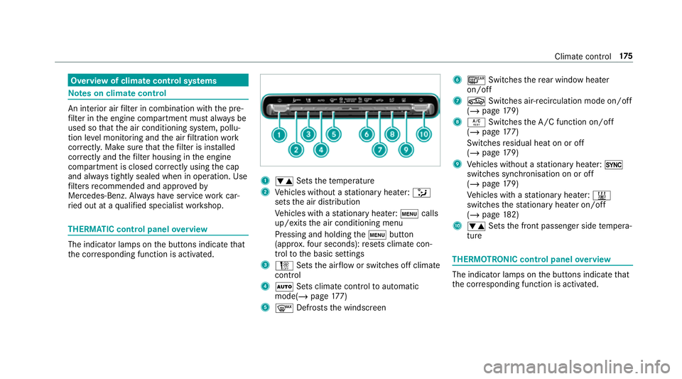
Overview of climate control sy
stems Note
s on climate control An interior air
filter in combination with the pre‐
fi lter in the engine compartment must alw ays be
used so that the air conditioning sy stem, pollu‐
tion le vel monitoring and the air filtration work
cor rectl y.Make sure that thefilter is ins talled
cor rectly and thefilter housing in the engine
compartment is closed cor rectly using the cap
and alw ays tightly sealed when in operation. Use
fi lters recommended and appr ovedby
Mercedes-Benz. Alw ays ha veservice workcar‐
ri ed out at a qualified specialist workshop. THERMATIC control panel
overview The indicator lamps on
the buttons indicate that
th e cor responding function is activated. 1
w Setsthete mp erature
2 Vehicles without a stationary heater: _
sets the air distribution
Ve hicles with a stationary heater: tcalls
up/exits the air conditioning menu
Pressing and holding thet button
(appr ox.fo ur seconds): resets climate con‐
trol tothe basic settings
3 H Setsthe air flow or switches off climate
control
4 Ã Sets climate control toautomatic
mode(/ page177)
5 ¬ Defrosts the windscreen 6
¤ Switches there ar wind owheater
on/off
7 g Switches air-recirculation mode on/off
(/ page 179)
8 Á Switches the A/C function on/off
(/ page 177)
Switches residual heat on or off
(/ page 179)
9 Vehicles without a stationary heater: 0
swit ches synchronisation on or off
(/ page 179)
Ve hicles with a stationary heater: &
swit ches thest ationary heater on/off
(/ page 182)
A w Setsthe front passenger side temp era‐
ture THERMOTRONIC control panel
overview The indicator lamps on
the buttons indicate that
th e cor responding function is activated. Climate
control 175