2019 MERCEDES-BENZ GLS SUV tire pressure
[x] Cancel search: tire pressurePage 375 of 398
ponents may also be damaged. There is a risk
of an accident.
Rotate front and rear wheels only if the wheels
and tires are of the same dimensions.
! On vehicles equipped with a tire pressure
monitor, electronic components are located
in the wheel.
Tire-mounting tools should not be used near
the valve. This could damage the electronic
components.
Only have tires changed at a qualified spe-
cialist workshop.
Always observe the instructions and safety
notes in the "Mounting a wheel" section
(Y page 373).
The wear patterns on the front and rear tires
differ, depending on the operating conditions.
Rotate the wheels before a clear wear pattern
has formed on the tires. Front tires typically
wear more on the shoulders and the rear tires in
the center.
On vehicles that have the same size front and
rear wheels, you can rotate the wheels accord-
ing to the intervals in the tire manufacturer's
warranty book in your vehicle documents. If no
warranty book is available, the tires should be
rotated every 3,000 to 6,000 miles (5,000 to
10,000 km). Depending on tire wear, this may
be required earlier. Do not change the direction
of wheel rotation.
Clean the contact surfaces of the wheel and the brake disc thoroughly every time a wheel is rota-
ted. Check the tire pressure and, if necessary,
restart the tire pressure loss warning system or
the tire pressure monitor (Y page 359).Direction of rotation
Tires with a specified direction of rotation have
additional benefits, e.g. if there is a risk of hydro-
planing. These advantages can only be gained if the tires are installed corresponding to the
direction of rotation.
An arrow on the sidewall of the tire indicates its
correct direction of rotation. Storing wheels
Store wheels that are not being used in a cool,
dry and preferably dark place. Protect the tires
from oil, grease, gasoline and diesel. Mounting a wheel
Preparing the vehicle X
Vehicle with emergency spare wheel:
when mounting the emergency spare wheel in
the event of a flat tire, follow the additional
notes on vehicle preparation under "Flat tire" (Y page 335).
X Stop the vehicle on solid, non-slippery and
level ground.
X Apply the electric parking brake manually.
X Bring the front wheels into the straight-ahead
position.
X Vehicles with automatic transmission:
shift the transmission to position
005D.
X Vehicles with the AIRMATIC package:
make sure that the normal vehicle level is
selected (Y page 187).
X Vehicles with the Off-Road Engineering
package:
make sure that the normal level is
selected (Y page 180).
X Switch off the engine.
X Vehicles without KEYLESS-GO: remove the
SmartKey from the ignition lock.
X Vehicles with KEYLESS-GO: open the driv-
er's door.
The vehicle electronics are now in position
0092. This means no SmartKey is in the ignition lock.
X Vehicles with KEYLESS-GO: remove the
Start/Stop button from the ignition lock
(Y page 140).
X If included in the vehicle equipment, remove
the tire-change tool kit from the vehicle.
X Safeguard the vehicle against rolling away.
i Apart from certain country-specific varia-
tions, vehicles are not equipped with a tire-
change tool kit. For more information on
which tools are required to perform a wheel
change on your vehicle, consult a qualified
specialist workshop. Changing a wheel
373Wheels and tires Z
Page 379 of 398
Lowering the vehicle
G
WARNING
The wheels could come loose if the wheel
bolts or wheel nuts are not tightened to the
prescribed tightening torque. There is a risk of an accident.
Ensure that the wheel bolts or wheel nuts are tightened to the prescribed tightening torque.
If you are not sure, do not move the vehicle.
Contact a qualified specialist workshop and
have the tightening torque checked immedi-
ately.
! Mercedes-AMG vehicles with a collapsi-
ble spare wheel: before lowering the vehicle,
inflate the collapsible spare wheel with the
tire inflation compressor. The wheel rim could
otherwise be damaged.
X Place the ratchet wrench onto the hexagon
nut of the jack so that the letters ABare visi-
ble.
X Turn the ratchet wrench until the vehicle is
once again standing firmly on the ground.
X Place the jack to one side. X
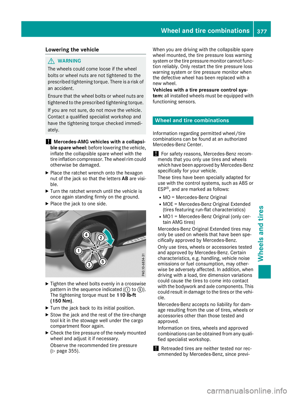
Tighten the wheel bolts evenly in a crosswise
pattern in the sequence indicated (0043 to0083).
The tightening torque must be 110 lb-ft
(150 Nm) .
X Turn the jack back to its initial position.
X Stow the jack and the rest of the tire-change
tool kit in the stowage well under the cargo
compartment floor again.
X Check the tire pressure of the newly mounted
wheel and adjust it if necessary.
Observe the recommended tire pressure
(Y page 355). When you are driving with the collapsible spare
wheel mounted, the tire pressure loss warning
system or the tire pressure monitor cannot func- tion reliably. Only restart the tire pressure loss
warning system or tire pressure monitor when
the defective wheel has been replaced with a
new wheel.
Vehicles with a tire pressure control sys-
tem: all installed wheels must be equipped with
functioning sensors. Wheel and tire combinations
Information regarding permitted wheel/tire
combinations can be found at an authorized
Mercedes-Benz Center.
! For safety reasons, Mercedes-Benz recom-
mends that you only use tires and wheels
which have been approved by Mercedes-Benz specifically for your vehicle.
These tires have been specially adapted for
use with the control systems, such as ABS or
ESP ®
, and are marked as follows:
R MO = Mercedes-Benz Original
R MOE = Mercedes-Benz Original Extended
(tires featuring run-flat characteristics)
R MO1 = Mercedes-Benz Original (only cer-
tain AMG tires)
Mercedes-Benz Original Extended tires may
only be used on wheels that have been spe-
cifically approved by Mercedes-Benz.
Only use tires, wheels or accessories tested
and approved by Mercedes-Benz. Certain
characteristics, e.g. handling, vehicle noise
emissions or fuel consumption, may other-
wise be adversely affected. In addition, when
driving with a load, tire dimension variations
could cause the tires to come into contact
with the bodywork and axle components. This
could result in damage to the tires or the vehi- cle.
Mercedes-Benz accepts no liability for dam-
age resulting from the use of tires, wheels or
accessories other than those tested and
approved.
Information on tires, wheels and approved
combinations can be obtained from any quali-fied specialist workshop.
! Retreaded tires are neither tested nor rec-
ommended by Mercedes-Benz, since previ- Wheel and tire combinations
377Wheels and tires Z
Page 380 of 398
ous damage cannot always be detected on
retreaded tires. As a result, Mercedes-Benz
cannot guarantee vehicle safety if retreaded
tires are mounted. Do not mount used tires if
you have no information about their previous
usage.
The recommended pressures for various oper-
ating conditions can be found:
R on the Tire and Loading Information placard
on the B-pillar on the driver's side
R in the tire pressure table in the fuel filler flap
Observe the notes on recommended tire pres-
sures under various operating conditions
(Y page 355).
Check tire pressures regularly, and only when
the tires are cold. Comply with the maintenance recommendations of the tire manufacturer in
the vehicle document wallet.
Notes on the vehicle equipment – always equip
the vehicle:
R with tires of the same size on a given axle (left
and right)
R with the same type of tires at a given time
(summer tires, winter tires, MOExtended
tires)
i Vehicles equipped with MOExtended tires
are not equipped with a TIREFIT kit at the fac- tory. It is therefore recommended that you
additionally equip your vehicle with a TIREFIT
kit if you mount tires that do not feature run- flat properties, e.g. winter tires. A TIREFIT kit
may be obtained from a qualified specialist
workshop. Emergency spare wheel
Important safety notes
G
WARNING
The wheel or tire size as well as the tire type of the spare wheel or emergency spare wheel
and the wheel to be replaced may differ.
Mounting an emergency spare wheel may
severely impair the driving characteristics.
There is a risk of an accident. To avoid hazardous situations:
R adapt your driving style accordingly and
drive carefully.
R never mount more than one spare wheel or
emergency spare wheel that differs in size.
R only use a spare wheel or emergency spare
wheel of a different size briefly.
R do not switch ESP ®
off.
R have a spare wheel or emergency spare
wheel of a different size replaced at the
nearest qualified specialist workshop.
Observe that the wheel and tire dimensions
as well as the tire type must be correct.
! Mercedes-AMG vehicles with
"Minispare" emergency spare wheel: only
use the "Minispare" emergency spare wheel
on the rear axle. If you mount the
"Minispare" emergency spare wheel on the
front axle, this could result in damage to the
brake system.
If a tire on the front axle is defective, an intact
wheel from the rear axle must first be
replaced with the "Minispare" emergency
spare wheel. The damaged wheel on the front
axle can then be replaced by the undamaged wheel from the rear axle.
Make sure to note the placard on the
"Minispare" emergency spare wheel.
When using an emergency spare wheel or spare wheel of a different size, you must not exceed
the maximum speed of 50 mph (80 km/h).
You should regularly check the pressure of the
emergency spare wheel, particularly prior to
long trips, and correct the pressure as neces-
sary (Y page 355). The value on the wheel is
valid.
Snow chains must not be mounted on emer-
gency spare wheels. General notes
Information regarding permitted emergency
spare wheels can be found at an authorized
Mercedes-Benz Center.
Mounting the emergency spare wheel is descri- bed under "Mounting a wheel" (Y page 373).
An emergency spare wheel may also be moun-
ted against the direction of rotation. Observe 378
Emergency spare wheelWheels and tires
Page 381 of 398
the time restriction on use as well as the speed
limitation specified on the emergency spare
wheel.
Replace the tires after six years at the latest,
regardless of wear. This also applies to the
emergency spare wheel.
When you are driving with the collapsible spare wheel mounted, the tire pressure loss warning
system or the tire pressure monitor cannot func-
tion reliably. Only restart the tire pressure loss
warning system or tire pressure monitor when
the defective wheel has been replaced with a
new wheel.
Vehicles with tire pressure monitor: after
mounting an emergency spare wheel, the sys-
tem may still display the tire pressure of the
removed wheel for a few minutes. The value dis- played for the mounted emergency spare wheelis not the same as the current tire pressure of
the emergency spare wheel. Removing/stowing the emergency
spare wheel
Vehicles with a "Minispare" emergency
spare wheel under the cargo compart-
ment floor Always observe the instructions and safety
notes in the "Mounting a wheel" section
(Y page 373).
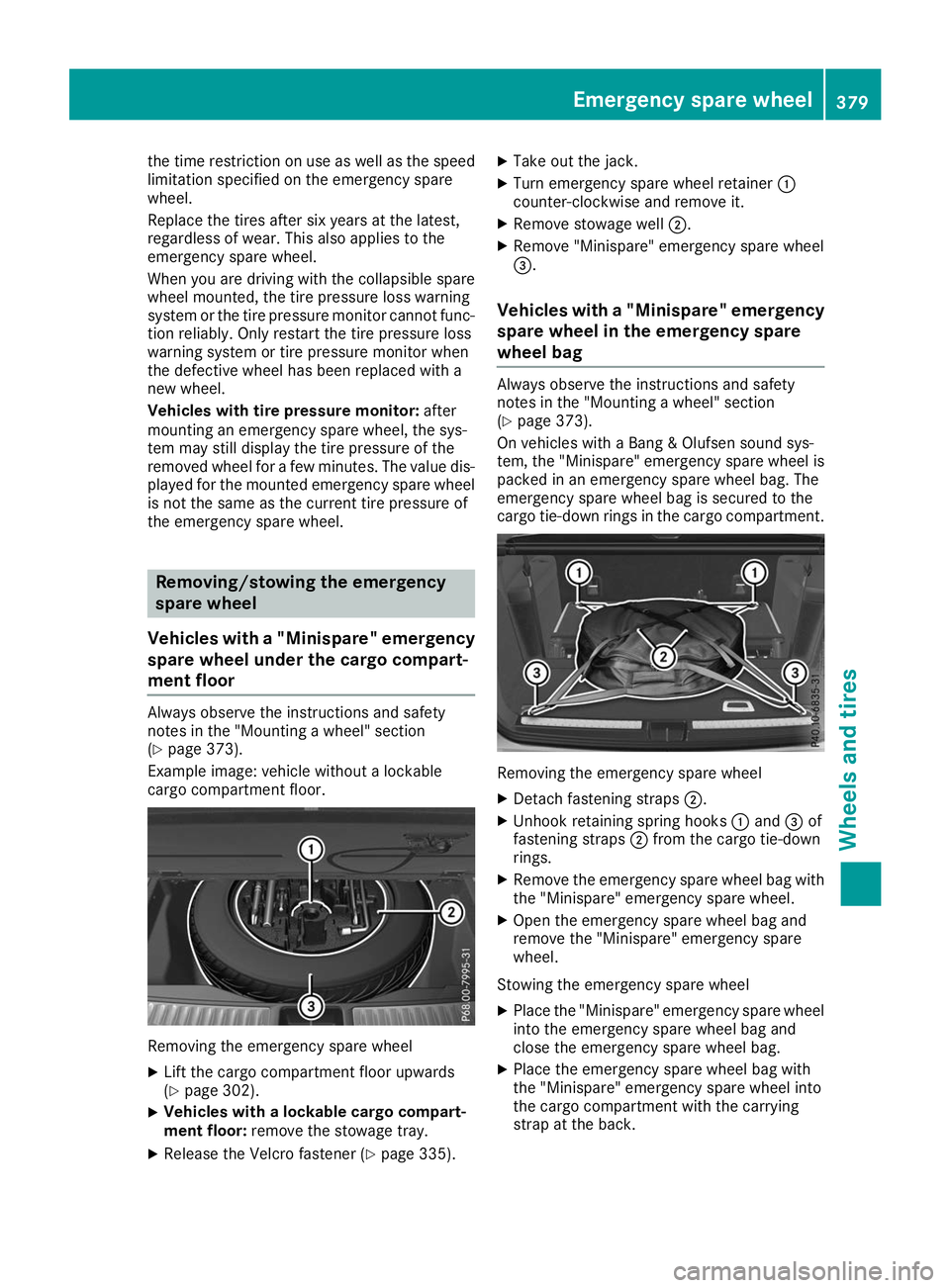
Example image: vehicle without a lockable
cargo compartment floor. Removing the emergency spare wheel
X Lift the cargo compartment floor upwards
(Y page 302).
X Vehicles with a lockable cargo compart-
ment floor: remove the stowage tray.
X Release the Velcro fastener (Y page 335).X
Take out the jack.
X Turn emergency spare wheel retainer 0043
counter-clockwise and remove it.
X Remove stowage well 0044.
X Remove "Minispare" emergency spare wheel
0087.
Vehicles with a "Minispare" emergency
spare wheel in the emergency spare
wheel bag Always observe the instructions and safety
notes in the "Mounting a wheel" section
(Y page 373).
On vehicles with a Bang & Olufsen sound sys-
tem, the "Minispare" emergency spare wheel is
packed in an emergency spare wheel bag. The
emergency spare wheel bag is secured to the
cargo tie-down rings in the cargo compartment. Removing the emergency spare wheel
X Detach fastening straps 0044.
X Unhook retaining spring hooks 0043and 0087of
fastening straps 0044from the cargo tie-down
rings.
X Remove the emergency spare wheel bag with
the "Minispare" emergency spare wheel.
X Open the emergency spare wheel bag and
remove the "Minispare" emergency spare
wheel.
Stowing the emergency spare wheel X Place the "Minispare" emergency spare wheel
into the emergency spare wheel bag and
close the emergency spare wheel bag.
X Place the emergency spare wheel bag with
the "Minispare" emergency spare wheel into
the cargo compartment with the carrying
strap at the back. Emergency spare
wheel
379Wheels an d tires Z
Page 383 of 398
compartment with the carrying strap at the
back.
X Hook retaining spring hooks 0043of fastening
strap 0044into the cargo tie-down rings.
X Tighten fastening strap 0044.Inflating the collapsible spare wheel
(Mercedes-AMG GLS 63 4MATIC)
! Inflate the collapsible spare wheel using the
tire inflation compressor before lowering the
vehicle. The wheel rim could otherwise be
damaged.
! Do not operate the tire inflation compressor
for longer than eight minutes at a time without
a break. It may otherwise overheat.
The tire inflation compressor can be operated again once it has cooled down.
Comply with the manufacturer's safety instruc-
tions on the tire inflation compressor label and
on the tire sealant bottle.
X Mount the collapsible spare wheel as descri-
bed (Y page 373).
The collapsible spare wheel must be mounted before it is inflated.
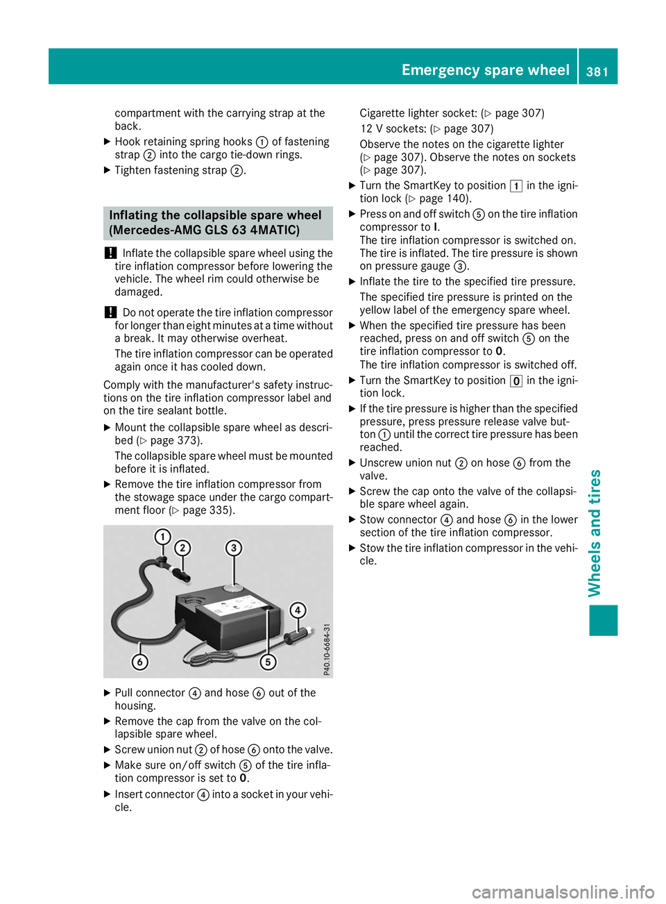
X Remove the tire inflation compressor from
the stowage space under the cargo compart-
ment floor (Y page 335). X
Pull connector 0085and hose 0084out of the
housing.
X Remove the cap from the valve on the col-
lapsible spare wheel.
X Screw union nut 0044of hose 0084onto the valve.
X Make sure on/off switch 0083of the tire infla-
tion compressor is set to 0.
X Insert connector 0085into a socket in your vehi-
cle. Cigarette lighter socket: (Y
page 307)
12 V sockets: (Y page 307)
Observe the notes on the cigarette lighter
(Y page 307). Observe the notes on sockets
(Y page 307).
X Turn the SmartKey to position 0047in the igni-
tion lock (Y page 140).
X Press on and off switch 0083on the tire inflation
compressor to I.
The tire inflation compressor is switched on.
The tire is inflated. The tire pressure is shown on pressure gauge 0087.
X Inflate the tire to the specified tire pressure.
The specified tire pressure is printed on the
yellow label of the emergency spare wheel.
X When the specified tire pressure has been
reached, press on and off switch 0083on the
tire inflation compressor to 0.
The tire inflation compressor is switched off.
X Turn the SmartKey to position 0092in the igni-
tion lock.
X If the tire pressure is higher than the specified
pressure, press pressure release valve but-
ton 0043until the correct tire pressure has been
reached.
X Unscrew union nut 0044on hose 0084from the
valve.
X Screw the cap onto the valve of the collapsi-
ble spare wheel again.
X Stow connector 0085and hose 0084in the lower
section of the tire inflation compressor.
X Stow the tire inflation compressor in the vehi-
cle. Emergency spare wheel
381Wheels and tires Z