2019 MERCEDES-BENZ GLS SUV height
[x] Cancel search: heightPage 183 of 398
ering is interrupted if a door is opened, and it
continues once the door has been closed.
Further information about "Driving off-road"
(Y page 166). G
WARNING
When the vehicle is being lowered, people
could become trapped if their limbs are
between the vehicle body and the wheels or
underneath the vehicle. There is a risk of
injury.
Make sure no one is underneath the vehicle or in the immediate vicinity of the wheel arches
when the vehicle is being lowered. G
WARNING
When you drive with the vehicle raised, the
driving characteristics could be impaired by
the vehicle's raised center of gravity. The vehi- cle could rollover more easily, for example on
a bend. There is a risk of an accident.
Always select as low a vehicle level as possi-
ble and adjust your driving style. G
WARNING
When you drive with the chassis lowered or
raised, the vehicle's braking and driving char-
acteristics can be significantly impaired. You
could also exceed the permissible vehicle
height if the chassis is raised. There is a risk of an accident.
Adjust the vehicle level before pulling away. G
WARNING
Due to the high center of gravity, the vehicle
may start to skid and roll over in the event of
an abrupt steering maneuver and/or when
the vehicle's speed is not adapted to the road conditions. There is a risk of an accident.
Always adapt your speed and driving style to
the vehicle's driving characteristics and to the prevailing road and weather conditions.
! When driving on extremely rough terrain,
select a high vehicle level in good time. Make
sure there is always sufficient ground clear-
ance. You will otherwise damage the vehicle. R
Utility vehicles have a significantly higher roll-
over rate than other types of vehicles.
Failure to operate this vehicle safely may
result in an accident, rollover of the vehicle,
and severe or fatal injury.
R In a rollover crash, an unbelted person is sig-
nificantly more likely to die than a person
wearing a seat belt.
You and all vehicle occupants should always
wear your seat belts.
Basic settings The extent to which the vehicle is raised or low-
ered depends on the basic setting selected.
Select:
R the Comfort orSport drive program for driv-
ing on normal roads
R the Offroad drive program for driving on eas-
ily negotiable off-road terrain
R the Offroad Plus drive program for off-road
driving
R offroad level 1 for driving on easily negotiable
off-road terrain
R offroad level 2 for driving on normal off-road
terrain
R offroad level 3 for freeing the vehicle in par-
ticularly rough terrain at low speeds only
The individual vehicle levels differ from the nor- mal level as follows:
R –0.6 in (–15 mm) in the Sportdrive program
R +/–0 in (+/–0 mm) in the Comfortdrive pro-
gram
R + 1.2 in (+ 30 mm) in the Offroaddrive pro-
gram
R + 2.4 in (+ 60 mm) in the Offroad Plusdrive
program
R + 1.2 in (+ 30 mm) in offroad level 1
R + 2.4 in (+ 60 mm) in offroad level 2
R + 3.5 in (+ 90 mm) in offroad level 3
Setting the vehicle level !
Make sure that there is enough ground
clearance when the vehicle is being lowered.
It could otherwise hit the ground, damaging
the underbody. Driving systems
181Driving and parking Z
Page 189 of 398
Vehicle level
Important safety notes
G
WARNING
When the vehicle is being lowered, people
could become trapped if their limbs are
between the vehicle body and the wheels or
underneath the vehicle. There is a risk of
injury.
Make sure no one is underneath the vehicle or in the immediate vicinity of the wheel arches
when the vehicle is being lowered. G
WARNING
When you drive with the vehicle raised, the
driving characteristics could be impaired by
the vehicle's raised center of gravity. The vehi- cle could rollover more easily, for example on
a bend. There is a risk of an accident.
Always select as low a vehicle level as possi-
ble and adjust your driving style. G
WARNING
When you drive with the chassis lowered or
raised, the vehicle's braking and driving char-
acteristics can be significantly impaired. You
could also exceed the permissible vehicle
height if the chassis is raised. There is a risk of an accident.
Adjust the vehicle level before pulling away. G
WARNING
Due to the high center of gravity, the vehicle
may start to skid and roll over in the event of
an abrupt steering maneuver and/or when
the vehicle's speed is not adapted to the road conditions. There is a risk of an accident.
Always adapt your speed and driving style to
the vehicle's driving characteristics and to the prevailing road and weather conditions.
! When driving on extremely rough terrain,
select a high vehicle level in good time. Make
sure there is always sufficient ground clear-
ance. You will otherwise damage the vehicle.
R Utility vehicles have a significantly higher roll-
over rate than other types of vehicles. Failure to operate this vehicle safely may
result in an accident, rollover of the vehicle,
and severe or fatal injury.
R In a rollover crash, an unbelted person is sig-
nificantly more likely to die than a person
wearing a seat belt.
You and all vehicle occupants should always
wear your seat belts.
General notes
Only select raised level if this is appropriate for
the road conditions. Otherwise, fuel consump-
tion may increase and handling may be affected.
Make changes to the vehicle level while the
vehicle is in motion. This enables the vehicle to adjust to the new level as quickly as possible.
The vehicle level may change visibly if you park
the vehicle and the outside temperature
changes. If the temperature drops, the vehicle
level is lower; with an increase in temperature,
the vehicle level rises.
If you unlock the vehicle or open a door, the
vehicle begins to compensate for load discrep-
ancies while still parked. However, for signifi-
cant level changes, such as after the vehicle has
been stationary for a long period, the engine
must be on. For safety reasons, the vehicle is
only lowered when the doors are closed. Low-
ering is interrupted if a door is opened, and it
continues once the door has been closed.
Vehicles with no trailer coupled: below a
speed of 37 mph (60 km/h) you can choose
between the normal and raised vehicle level.
Select the normal vehicle level for normal road
surfaces and the raised vehicle level for driving
with snow chains or on particularly poor road
surfaces. Your selection remains stored even if
you remove the SmartKey from the ignition lock.
If you try to select raised level at a speed above
37 mph (60 km/h), the Drive More Slowly
Drive More Slowly
message appears in the multifunction display.
Vehicles with a trailer coupled: below a speed
of 19 mph (30 km/h), you can choose between
the normal and raised vehicle level. Driving systems
187Driving and parking Z
Page 190 of 398
Setting the raised vehicle level
X
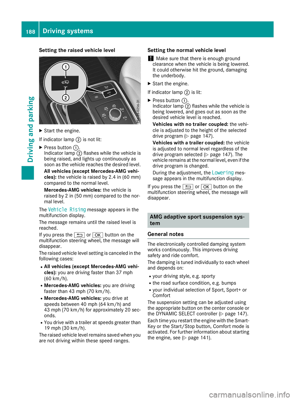
Start the engine.
If indicator lamp 0044is not lit:
X Press button 0043.
Indicator lamp 0044flashes while the vehicle is
being raised, and lights up continuously as
soon as the vehicle reaches the desired level.
All vehicles (except Mercedes-AMG vehi-
cles): the vehicle is raised by 2.4 in (60 mm)
compared to the normal level.
Mercedes-AMG vehicles: the vehicle is
raised by 2 in (50 mm) compared to the nor-
mal level.
The Vehicle Rising Vehicle Rising message appears in the
multifunction display.
The message remains until the raised level is
reached.
If you press the 0038or0076 button on the
multifunction steering wheel, the message will
disappear.
The raised vehicle level setting is canceled in the following cases:
R All vehicles (except Mercedes-AMG vehi-
cles): you are driving faster than 37 mph
(60 km/h).
R Mercedes-AMG vehicles: you are driving
faster than 43 mph (70 km/h).
R Mercedes-AMG vehicles: you drive at
speeds between 40 mph (64 km/h) and
43 mph (70 km/h) for approximately 20 sec- onds.
R You drive with a trailer at speeds greater than
19 mph (30 km/h).
The raised vehicle level remains saved when you are not driving within these speed ranges. Setting the normal vehicle level
! Make sure that there is enough ground
clearance when the vehicle is being lowered.
It could otherwise hit the ground, damaging
the underbody.
X Start the engine.
If indicator lamp 0044is lit:
X Press button 0043.
Indicator lamp 0044flashes while the vehicle is
being lowered, and goes out as soon as the
desired vehicle level is reached.
Vehicles with no trailer coupled: the vehi-
cle is adjusted to the height of the selected
drive program (Y page 147).
Vehicles with a trailer coupled: the vehicle
is adjusted to normal level regardless of the
drive program selected (Y page 147). The
vehicle remains at the normal level, even if the
drive program is changed.
During the adjustment, the Lowering
Lowering mes-
sage appears in the multifunction display.
If you press the 0038or0076 button on the
multifunction steering wheel, the message will
disappear. AMG adaptive sport suspension sys-
tem
General notes The electronically controlled damping system
works continuously. This improves driving
safety and ride comfort.
The damping is tuned individually to each wheel and depends on:
R your driving style, e.g. sporty
R the road surface condition, e.g. bumps
R your individual selection of Sport, Sport+ or
Comfort
The suspension setting can be adjusted using
the appropriate button on the center console or the DYNAMIC SELECT controller (Y page 147).
Each time you restart the engine with the Smart-
Key or the Start/Stop button, Comfort mode is
activated. For further information about starting
the engine, see (Y page 141).188
Driving systemsDriving and parking
Page 199 of 398
R
if the camera lens is dirty or obstructed.
Observe the notes on cleaning
(Y page 330)
R if the rear of your vehicle is damaged. In this
event, have the camera position and setting
checked at a qualified specialist workshop
The field of vision and other functions of the rear
view camera may be restricted due to additional
accessories on the rear of the vehicle (e.g.
license plate holder, bicycle rack).
On vehicles with height-adjustable chassis,
leaving the standard height can result in inac-
curacies in the guide lines, depending on tech-
nical conditions.
i The contrast of the display may be affected
by the sudden presence of sunlight or other
light sources, e.g. when exiting a garage. Pay
particular attention in this situation.
i If usability is severely restricted, e.g. due to
pixel errors, have the display repaired or
replaced.
i The rear view camera is protected from rain-
drops and dust by means of a flap. When the
rear view camera is activated, this flap opens.
The flap closes again when:
R you have finished the maneuvering process
R you switch off the engine
R you open the cargo compartment
Observe the notes on cleaning (Y page 330).
For technical reasons, the flap may remain
open briefly after the rear view camera has
been deactivated.
Activating/deactivating the rear view
camera X
To activate: make sure that the SmartKey is
in position 0048in the ignition lock.
X Make sure that the Activation by R gear
Activation by R gear
function is selected on the multimedia system (see the Digital Operator's Manual).
X Engage reverse gear.
The rear view camera flap opens. The multi-
media system shows the area behind the vehi-
cle with guide lines.
The image from the rear view camera is avail- able throughout the maneuvering process.
X To switch the function mode for vehicles
with trailer tow hitch: using the controller,
select symbol 0043for the "Reverse parking" function or symbol
0044for "Coupling up a
trailer".
The symbol of the selected function is high-
lighted.
To deactivate: shift the transmission to posi-
tion 005Dor drive forwards.
Displays in the multimedia system The rear view camera may show a distorted view
of obstacles, show them incorrectly or not at all.
The rear view camera does not show objects in
the following positions:
R very close to the rear bumper
R under the rear bumper
R in the area immediately above the tailgate
handle
! Objects not at ground level may appear to
be further away than they actually are, e.g.:
R the bumper of a parked vehicle
R the drawbar of a trailer
R the ball coupling of a trailer tow hitch
R the rear section of an HGV
R a slanted post
Use the guidelines only for orientation.
Approach objects no further than the bottom-
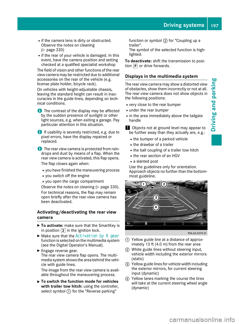
most guideline. 0043
Yellow guide line at a distance of approx-
imately 13 ft (4.0 m) from the rear area
0044 White guide lines without steering input,
vehicle width including the exterior mirrors
(static)
0087 Yellow guide lines for vehicle width including
the exterior mirrors, for current steering
input (dynamic)
0085 Yellow lanes marking the course the tires
will take at the current steering wheel angle
(dynamic) Driving systems
197Driving and parking Z
Page 202 of 398
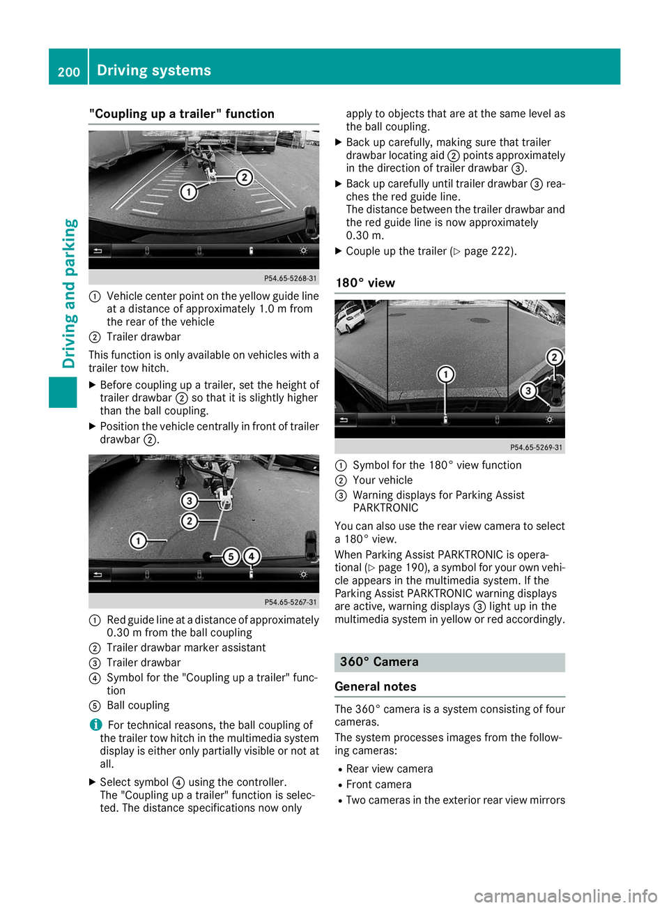
"Coupling up a trailer" function
0043
Vehicle center point on the yellow guide line
at a distance of approximately 1.0 m from
the rear of the vehicle
0044 Trailer drawbar
This function is only available on vehicles with a
trailer tow hitch.
X Before coupling up a trailer, set the height of
trailer drawbar 0044so that it is slightly higher
than the ball coupling.
X Position the vehicle centrally in front of trailer
drawbar 0044. 0043
Red guide line at a distance of approximately
0.30 m from the ball coupling
0044 Trailer drawbar marker assistant
0087 Trailer drawbar
0085 Symbol for the "Coupling up a trailer" func-
tion
0083 Ball coupling
i For technical reasons, the ball coupling of
the trailer tow hitch in the multimedia system
display is either only partially visible or not at all.
X Select symbol 0085using the controller.
The "Coupling up a trailer" function is selec-
ted. The distance specifications now only apply to objects that are at the same level as
the ball coupling.
X Back up carefully, making sure that trailer
drawbar locating aid 0044points approximately
in the direction of trailer drawbar 0087.
X Back up carefully until trailer drawbar 0087rea-
ches the red guide line.
The distance between the trailer drawbar and the red guide line is now approximately
0.30 m.
X Couple up the trailer (Y page 222).
180° view 0043
Symbol for the 180° view function
0044 Your vehicle
0087 Warning displays for Parking Assist
PARKTRONIC
You can also use the rear view camera to select
a 180° view.
When Parking Assist PARKTRONIC is opera-
tional (Y page 190), a symbol for your own vehi-
cle appears in the multimedia system. If the
Parking Assist PARKTRONIC warning displays
are active, warning displays 0087light up in the
multimedia system in yellow or red accordingly. 360° Camera
General notes The 360° camera is a system consisting of four
cameras.
The system processes images from the follow-
ing cameras:
R Rear view camera
R Front camera
R Two cameras in the exterior rear view mirrors 200
Driving systemsDriving and parking
Page 204 of 398
Guide lines are always shown at road level. In
trailer mode, the guide lines are shown at the
level of the trailer coupling.
The field of vision and other functions of the
camera system may be restricted due to addi-
tional accessories on the rear of the vehicle (e.g.
license plate holder, bicycle rack).
On vehicles with height-adjustable chassis,
depending on technical conditions, leaving the
standard height can result in:
R inaccuracies in the guide lines
R inaccuracies in the display of generated
images (top view)
Activation conditions The 360° camera image can be displayed in the
following situations:
R your vehicle is equipped with a 360° camera
R the SmartKey is in key position 0048in the igni-
tion lock
R the multimedia system is switched on
Switching on the 360° camera X
Press the 00D4button in the center console
for longer than two seconds.
Depending on whether transmission position
005B or005E is selected, the following appears:
R a split screen with top view and the image
from the front camera or
R a split screen with top view and the image
from the rear view camera
or
X Press the 00D4button in the center console.
The vehicle menu is displayed.
X Select 360°
360° Camera Camera and press 7to confirm.
Depending on whether transmission position
005B or005E is selected, the following appears:
R a split screen with top view and the image
from the front camera or
R a split screen with top view and the image
from the rear view camera
Activating the 360° camera using
reverse gear The 360° camera images can be automatically
displayed by engaging reverse gear. X
Make sure that the SmartKey is in position 0048
in the ignition lock.
X Make sure that the Activation by R gear Activation by R gear
function is selected on the multimedia system (see the Digital Operator's Manual).
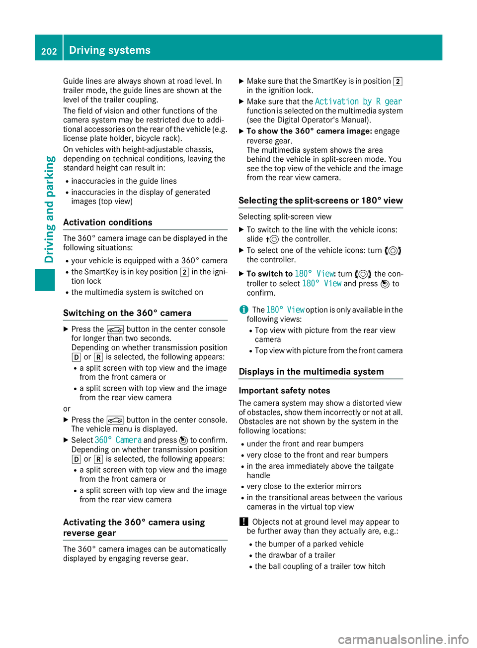
X To show the 360° camera image: engage
reverse gear.
The multimedia system shows the area
behind the vehicle in split-screen mode. You
see the top view of the vehicle and the image from the rear view camera.
Selecting the split-screens or 180° view Selecting split-screen view
X To switch to the line with the vehicle icons:
slide 5the controller.
X To select one of the vehicle icons: turn 3
the controller.
X To switch to 180° View
180° View :turn 3 the con-
troller to select 180° View
180° View and press7to
confirm.
i The
180° 180° View
Viewoption is only available in the
following views:
R Top view with picture from the rear view
camera
R Top view with picture from the front camera
Displays in the multimedia system Important safety notes
The camera system may show a distorted view
of obstacles, show them incorrectly or not at all. Obstacles are not shown by the system in the
following locations:
R under the front and rear bumpers
R very close to the front and rear bumpers
R in the area immediately above the tailgate
handle
R very close to the exterior mirrors
R in the transitional areas between the various
cameras in the virtual top view
! Objects not at ground level may appear to
be further away than they actually are, e.g.:
R the bumper of a parked vehicle
R the drawbar of a trailer
R the ball coupling of a trailer tow hitch 202
Driving systemsDriving and parking
Page 224 of 398
R
is affected more by strong crosswinds
R demands more sensitive steering
R has a larger turning circle
This could impair the handling characteristics.
When towing a trailer, always adjust your speed to the current road and weather conditions. Do
not exceed the maximum permissible speed for
your vehicle/trailer combination. Notes on towing a trailer
General notes !
If you have a trailer tow hitch retrofitted,
changes to the cooling system and drive train may be necessary, depending on the vehicle
type.
If you have a trailer tow hitch retrofitted,
observe the anchorage points on the chassis
frame.
R Do not exceed the legally prescribed maxi-
mum speed for vehicle/trailer combinations
in the relevant country.
This lowers the risk of an accident.
R Only install an approved trailer coupling on
your vehicle.
More information on availability and installa-
tion can be obtained at any qualified special-
ist workshop.
R The bumpers of your vehicle are not suitable
for installing detachable trailer couplings.
R Do not install hired trailer couplings or other
detachable trailer couplings on the bumpers
of your vehicle.
R If you no longer need the ball coupling,
remove it from the ball coupling recess. This
will reduce the risk of damage to the ball cou-
pling.
When towing a trailer, set the tire pressure on
the rear axle of the towing vehicle for the max-
imum load. You will find the values in the tire
pressure table in the fuel filler flap of the vehicle (Y page 371).
Please note that when towing a trailer, the fol-
lowing driving systems have limited availability
or are not available at all:
R Parking Assist PARKTRONIC (Y page 189)
R Blind Spot Assist (Y page 207)
R Active Lane Keeping Assist (Y page 212)On vehicles without level control, the height of
the ball coupling will alter according to the load
placed on the vehicle. If necessary, use a trailer
with a height-adjustable drawbar.
You will find installing dimensions and loads
under "Technical data" (Y page 392).
Driving tips Also observe the notes on pulling away with a
trailer (Y
page 143).
The maximum permissible speed for vehicle/
trailer combinations depends on the type of
trailer. Before beginning the journey, check the
trailer's documents to see what the maximum
permissible speed is for your trailer. Observe the
legally permissible maximum speed in the rele-
vant country.
For certain Mercedes-Benz vehicles, the maxi-
mum permissible rear axle load is increased
when towing a trailer. See "Technical data" to
find out whether this applies to your vehicle
(Y page 392). If you utilize any of the added
maximum rear axle load when towing a trailer,
the vehicle/trailer combination may not exceed
a maximum speed of 60 mph (100 km/h) for
reasons concerning the operating permit. This
also applies in countries in which the maximum
permissible speed for car/trailer combinations
is greater than 60 mph (100 km/h).
When towing a trailer, your vehicle's handling
characteristics will be different in comparison
with when driving without a trailer.
Use the left-hand steering wheel paddle shifter
to shift into a lower gear in good time on long
and steep downhill gradients.
This also applies if you have activated cruise
control or Active Distance Assist DISTRONIC.
This will use the braking effect of the engine, so that less braking will be required to maintain the
speed. This relieves the load on the brake sys-
tem and prevents the brakes from overheating
and wearing too quickly. If you need additional
braking, depress the brake pedal repeatedly
rather than continuously.
Driving tips If the trailer swings from side to side:
X Do not accelerate.
X Do not counter-steer.
X Brake if necessary. 222
Towing a trailerDriving and parking
Page 230 of 398
Use only bicycle racks approved by
Mercedes-Benz.
Bicycle racks cause your vehicle's driving char-
acteristics to change. The vehicle: R is heavier
R is restricted in its acceleration and gradient-
climbing capability
R has an increased braking distance This could impair the handling characteristics.
Adapt your driving style accordingly. Maintain a
safe distance and drive carefully.
When using bicycle racks, set the tire pressure
on the rear axle of the vehicle for the maximum
load. Further information on tire pressure can be
found on the tire pressure table (Y page 355).Loading instructions
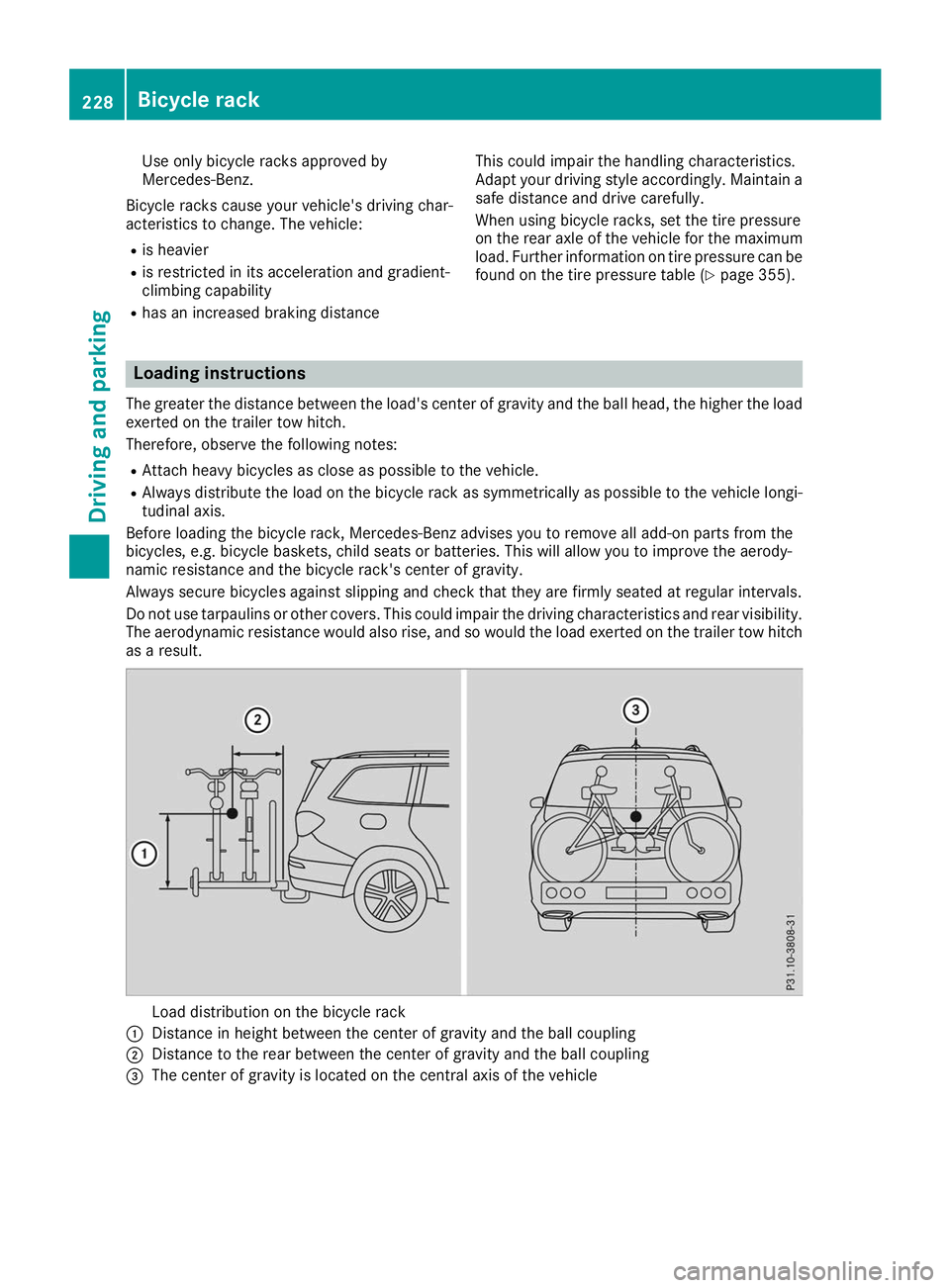
The greater the distance between the load's center of gravity and the ball head, the higher the load exerted on the trailer tow hitch.
Therefore, observe the following notes:
R Attach heavy bicycles as close as possible to the vehicle.
R Always distribute the load on the bicycle rack as symmetrically as possible to the vehicle longi-
tudinal axis.
Before loading the bicycle rack, Mercedes-Benz advises you to remove all add-on parts from the
bicycles, e.g. bicycle baskets, child seats or batteries. This will allow you to improve the aerody-
namic resistance and the bicycle rack's center of gravity.
Always secure bicycles against slipping and check that they are firmly seated at regular intervals.
Do not use tarpaulins or other covers. This could impair the driving characteristics and rear visibility. The aerodynamic resistance would also rise, and so would the load exerted on the trailer tow hitchas a result. Load distribution on the bicycle rack
0043 Distance in height between the center of gravity and the ball coupling
0044 Distance to the rear between the center of gravity and the ball coupling
0087 The center of gravity is located on the central axis of the vehicle 228
Bicycle rackDriving and parking