2019 MERCEDES-BENZ GLS SUV tow
[x] Cancel search: towPage 381 of 398
the time restriction on use as well as the speed
limitation specified on the emergency spare
wheel.
Replace the tires after six years at the latest,
regardless of wear. This also applies to the
emergency spare wheel.
When you are driving with the collapsible spare wheel mounted, the tire pressure loss warning
system or the tire pressure monitor cannot func-
tion reliably. Only restart the tire pressure loss
warning system or tire pressure monitor when
the defective wheel has been replaced with a
new wheel.
Vehicles with tire pressure monitor: after
mounting an emergency spare wheel, the sys-
tem may still display the tire pressure of the
removed wheel for a few minutes. The value dis- played for the mounted emergency spare wheelis not the same as the current tire pressure of
the emergency spare wheel. Removing/stowing the emergency
spare wheel
Vehicles with a "Minispare" emergency
spare wheel under the cargo compart-
ment floor Always observe the instructions and safety
notes in the "Mounting a wheel" section
(Y page 373).
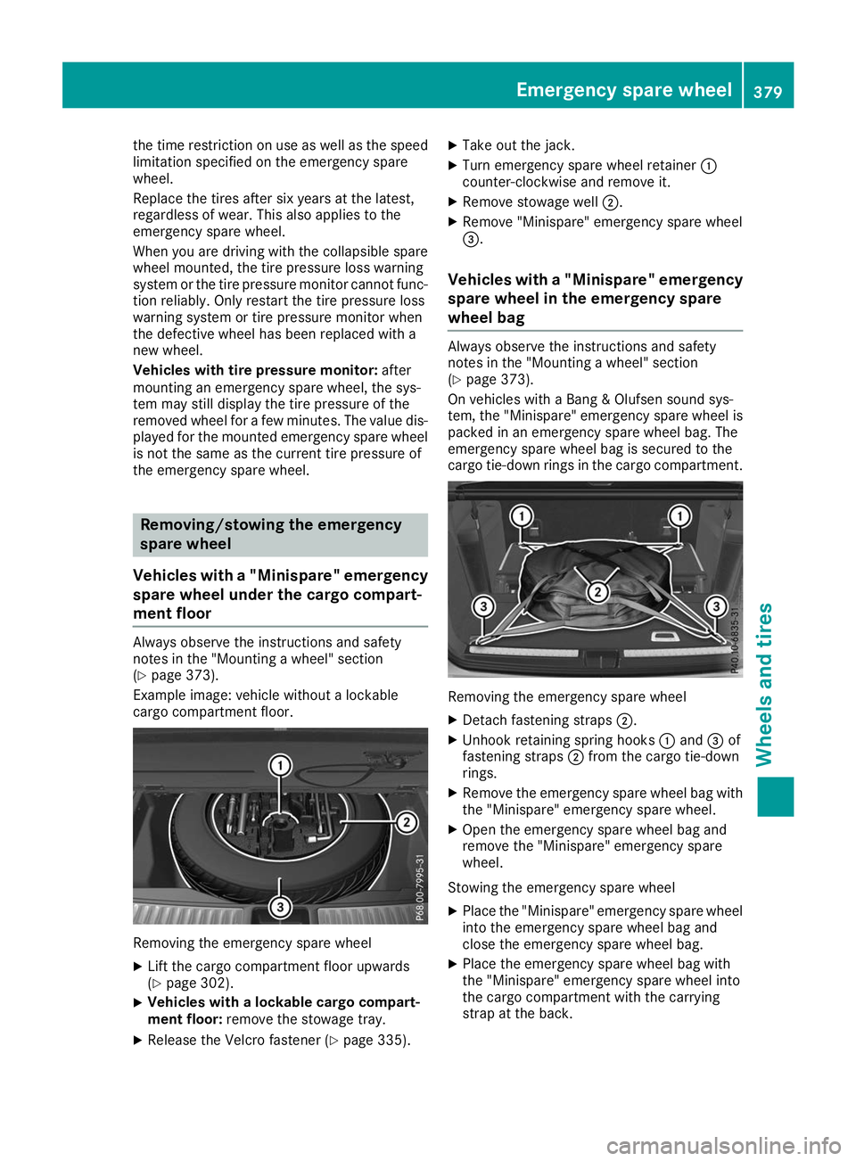
Example image: vehicle without a lockable
cargo compartment floor. Removing the emergency spare wheel
X Lift the cargo compartment floor upwards
(Y page 302).
X Vehicles with a lockable cargo compart-
ment floor: remove the stowage tray.
X Release the Velcro fastener (Y page 335).X
Take out the jack.
X Turn emergency spare wheel retainer 0043
counter-clockwise and remove it.
X Remove stowage well 0044.
X Remove "Minispare" emergency spare wheel
0087.
Vehicles with a "Minispare" emergency
spare wheel in the emergency spare
wheel bag Always observe the instructions and safety
notes in the "Mounting a wheel" section
(Y page 373).
On vehicles with a Bang & Olufsen sound sys-
tem, the "Minispare" emergency spare wheel is
packed in an emergency spare wheel bag. The
emergency spare wheel bag is secured to the
cargo tie-down rings in the cargo compartment. Removing the emergency spare wheel
X Detach fastening straps 0044.
X Unhook retaining spring hooks 0043and 0087of
fastening straps 0044from the cargo tie-down
rings.
X Remove the emergency spare wheel bag with
the "Minispare" emergency spare wheel.
X Open the emergency spare wheel bag and
remove the "Minispare" emergency spare
wheel.
Stowing the emergency spare wheel X Place the "Minispare" emergency spare wheel
into the emergency spare wheel bag and
close the emergency spare wheel bag.
X Place the emergency spare wheel bag with
the "Minispare" emergency spare wheel into
the cargo compartment with the carrying
strap at the back. Emergency spare
wheel
379Wheels an d tires Z
Page 382 of 398
X
Hook retaining spring hooks 0043and 0087of
fastening straps 0044into the cargo tie-down
rings.
X Tighten fastening straps 0044.
Mercedes-AMG vehicles with a collaps-
ible spare wheel under the cargo com-
partment floor !
Only place the collapsible spare wheel in the
vehicle when it is dry. Otherwise, moisture
may get into the vehicle.
Always observe the instructions and safety
notes in the "Mounting a wheel" section
(Y page 373).
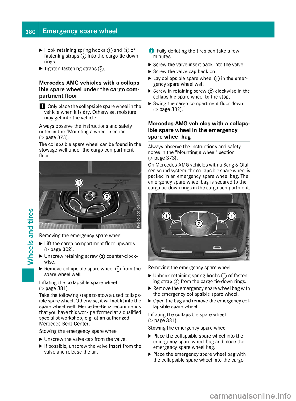
The collapsible spare wheel can be found in the stowage well under the cargo compartment
floor. Removing the emergency spare wheel
X Lift the cargo compartment floor upwards
(Y page 302).
X Unscrew retaining screw 0044counter-clock-
wise.
X Remove collapsible spare wheel 0043from the
spare wheel well.
Inflating the collapsible spare wheel
(Y page 381).
Take the following steps to stow a used collaps- ible spare wheel. Otherwise, it will not fit into the
spare wheel well. Mercedes-Benz recommends
that you have this work performed at a qualified
specialist workshop, e.g. at an authorized
Mercedes-Benz Center.
Stowing the emergency spare wheel
X Unscrew the valve cap from the valve.
X If possible, unscrew the valve insert from the
valve and release the air. i
Fully deflating the tires can take a few
minutes.
X Screw the valve insert back into the valve.
X Screw the valve cap back on.
X Lay collapsible spare wheel 0043in the emer-
gency spare wheel well.
X Screw in retaining screw 0044clockwise in the
collapsible spare wheel to the stop.
X Swing the cargo compartment floor down
(Y page 302).
Mercedes-AMG vehicles with a collaps-
ible spare wheel in the emergency
spare wheel bag Always observe the instructions and safety
notes in the "Mounting a wheel" section
(Y
page 373).
On Mercedes-AMG vehicles with a Bang & Oluf-
sen sound system, the collapsible spare wheel is
packed in an emergency spare wheel bag. The
emergency spare wheel bag is secured to the
cargo tie-down rings in the cargo compartment. Removing the emergency spare wheel
X Unhook retaining spring hooks 0043of fasten-
ing strap 0044from the cargo tie-down rings.
X Remove the emergency spare wheel bag with
the emergency collapsible spare wheel.
X Open the bag and remove the emergency col-
lapsible spare wheel.
Inflating the collapsible spare wheel
(Y page 381).
Stowing the emergency spare wheel
X Place the collapsible spare wheel into the
emergency spare wheel bag and close the
emergency spare wheel bag.
X Place the emergency spare wheel bag with
the collapsible spare wheel into the cargo 380
Emergency spare wheelWheels and tires
Page 383 of 398
compartment with the carrying strap at the
back.
X Hook retaining spring hooks 0043of fastening
strap 0044into the cargo tie-down rings.
X Tighten fastening strap 0044.Inflating the collapsible spare wheel
(Mercedes-AMG GLS 63 4MATIC)
! Inflate the collapsible spare wheel using the
tire inflation compressor before lowering the
vehicle. The wheel rim could otherwise be
damaged.
! Do not operate the tire inflation compressor
for longer than eight minutes at a time without
a break. It may otherwise overheat.
The tire inflation compressor can be operated again once it has cooled down.
Comply with the manufacturer's safety instruc-
tions on the tire inflation compressor label and
on the tire sealant bottle.
X Mount the collapsible spare wheel as descri-
bed (Y page 373).
The collapsible spare wheel must be mounted before it is inflated.
X Remove the tire inflation compressor from
the stowage space under the cargo compart-
ment floor (Y page 335). X
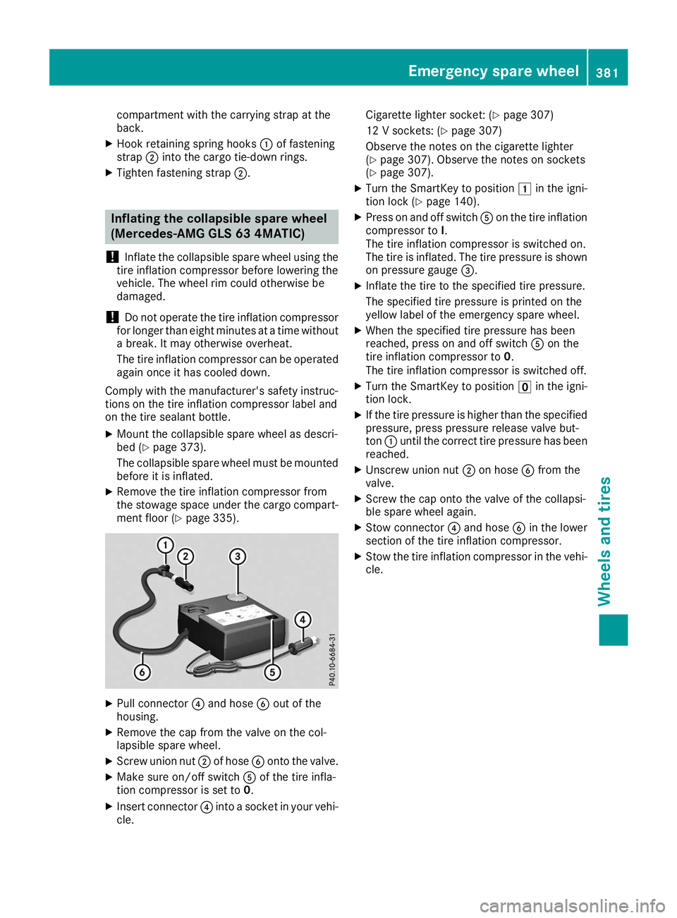
Pull connector 0085and hose 0084out of the
housing.
X Remove the cap from the valve on the col-
lapsible spare wheel.
X Screw union nut 0044of hose 0084onto the valve.
X Make sure on/off switch 0083of the tire infla-
tion compressor is set to 0.
X Insert connector 0085into a socket in your vehi-
cle. Cigarette lighter socket: (Y
page 307)
12 V sockets: (Y page 307)
Observe the notes on the cigarette lighter
(Y page 307). Observe the notes on sockets
(Y page 307).
X Turn the SmartKey to position 0047in the igni-
tion lock (Y page 140).
X Press on and off switch 0083on the tire inflation
compressor to I.
The tire inflation compressor is switched on.
The tire is inflated. The tire pressure is shown on pressure gauge 0087.
X Inflate the tire to the specified tire pressure.
The specified tire pressure is printed on the
yellow label of the emergency spare wheel.
X When the specified tire pressure has been
reached, press on and off switch 0083on the
tire inflation compressor to 0.
The tire inflation compressor is switched off.
X Turn the SmartKey to position 0092in the igni-
tion lock.
X If the tire pressure is higher than the specified
pressure, press pressure release valve but-
ton 0043until the correct tire pressure has been
reached.
X Unscrew union nut 0044on hose 0084from the
valve.
X Screw the cap onto the valve of the collapsi-
ble spare wheel again.
X Stow connector 0085and hose 0084in the lower
section of the tire inflation compressor.
X Stow the tire inflation compressor in the vehi-
cle. Emergency spare wheel
381Wheels and tires Z
Page 394 of 398
Maximum gradient-climbing capabil-
ity
Note that the vehicle's gradient-climbing capa-
bility depends on the off-road conditions and the road surface conditions.
Missing values were not available at time of
going to print. Model Maximum gradient-
climbing capability Vehicles without
the Offroad Engi-
neering package
80%
Vehicles with the
Off-Road Engineer-
ing package
With LOW RANGE off-
road gear switched
on 100%
Mercedes-AMG
GLS 63 4MATIC
If the load on the front axle is reduced when
pulling away on a steep uphill slope, the front
wheels have a tendency to spin. Accelerate
carefully and make sure that the wheels do not
spin when driving on steep terrain.
For further information about the maximum gra- dient climbing ability, see (Y page 170).Trailer tow hitch
Mounting dimensions
! If you have a trailer tow hitch retrofitted,
changes to the cooling system and drive train
may be necessary, depending on the vehicle
type.
If you have a trailer tow hitch retrofitted,
observe the anchorage points on the chassis
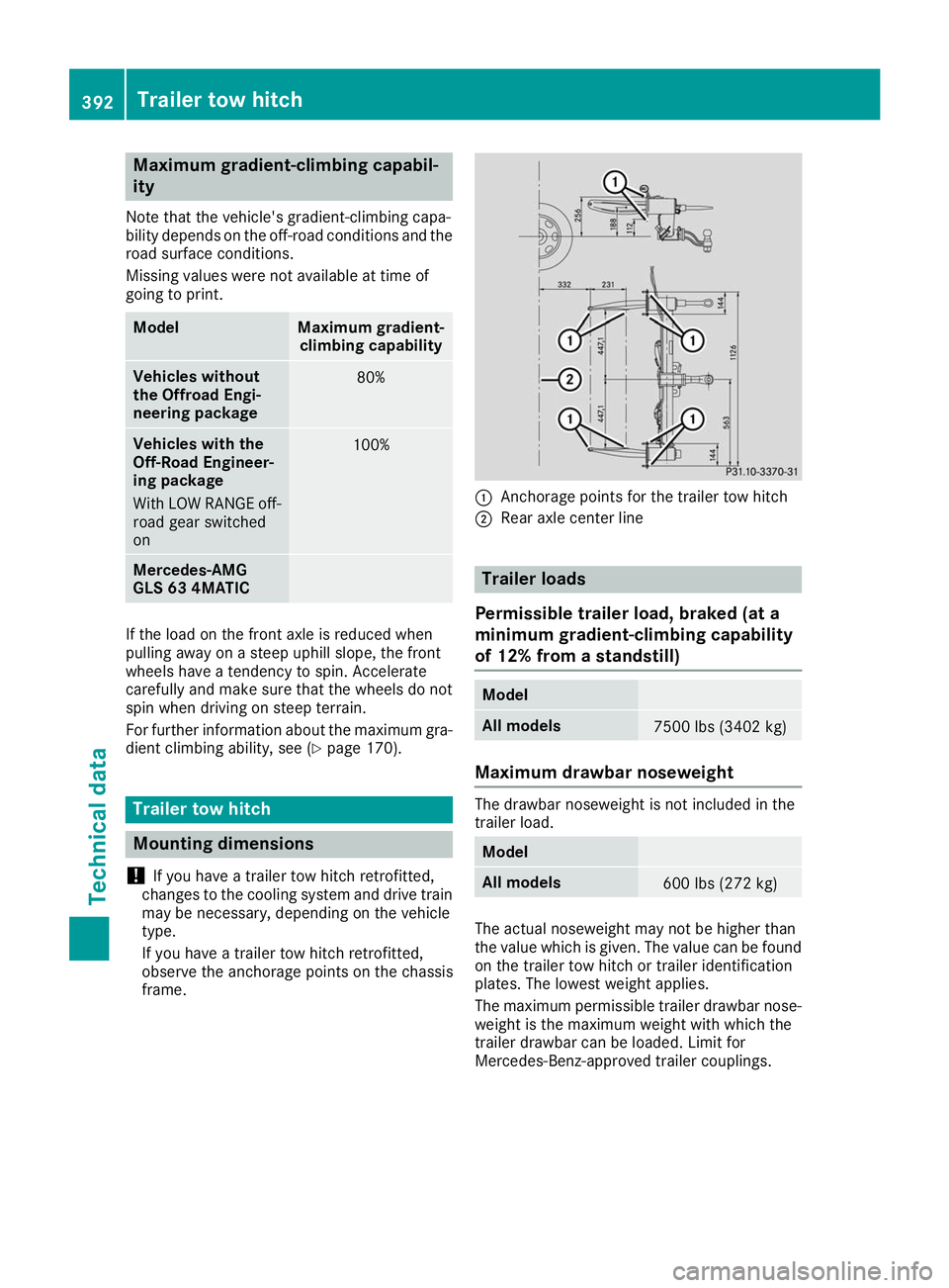
frame. 0043
Anchorage points for the trailer tow hitch
0044 Rear axle center line Trailer loads
Permissible trailer load, braked (at a
minimum gradient-climbing capability
of 12% from a standstill) Model
All models
7500 lbs (3402 kg)
Maximum drawbar noseweight
The drawbar noseweight is not included in the
trailer load.
Model
All models
600 lbs (272 kg)
The actual noseweight may not be higher than
the value which is given. The value can be found
on the trailer tow hitch or trailer identification
plates. The lowest weight applies.
The maximum permissible trailer drawbar nose-
weight is the maximum weight with which the
trailer drawbar can be loaded. Limit for
Mercedes-Benz-approved trailer couplings. 392
Trailer tow hitchTechnical data
Page 395 of 398
Permissible rear axle load when towing
a trailer Model
All models
3968 lbs (1800 kg)
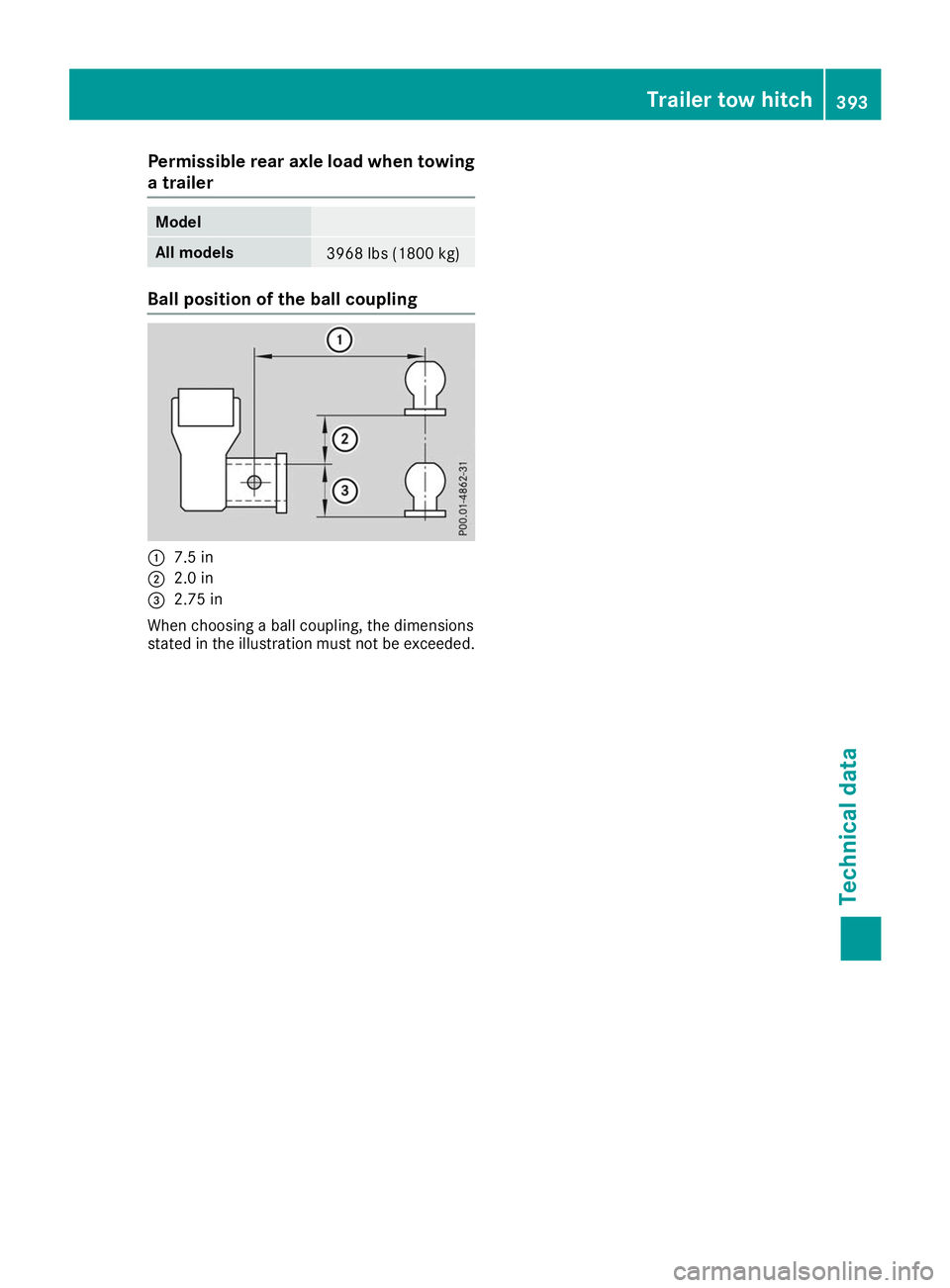
Ball position of the ball coupling
0043
7.5 in
0044 2.0 in
0087 2.75 in
When choosing a ball coupling, the dimensions
stated in the illustration must not be exceeded. Trailer tow hitch
393Technical data Z