2019 MERCEDES-BENZ GLS SUV tow
[x] Cancel search: towPage 341 of 398
Tire pressure not reached
If a pressure of 180 kPa (1.8 bar/26 psi) has not
been attained after five minutes:
X Switch off the tire inflation compressor.
X Unscrew the filler hose from the valve of the
faulty tire.
Note that tire sealant may escape when you
unscrew the filler hose.
X Very slowly drive forwards or reverse approx-
imately 30 ft (10 m).
X Pump up the tire again.
After a maximum of five minutes the tire pres-
sure must be at least 180 kPa (1.8 bar/
26 psi). G
WARNING
If the required tire pressure is not reached
after the specified time, the tire is too badly
damaged. The tire sealant cannot repair the
tire in this instance. Damaged tires and a tire pressure that is too low can significantly
impair the vehicle's braking and driving char-
acteristics. There is a risk of accident.
Do not continue driving. Contact a qualified
specialist workshop.
Tire pressure reached G
WARNING
A tire temporarily sealed with tire sealant
impairs the vehicle's driving characteristics
and is not suitable for driving at higher
speeds. There is a risk of an accident.
Adapt your driving style accordingly and drive carefully. Do not exceed the maximum per-
missible speed for a tire sealed with tire seal- ant.
The maximum permissible speed for a tire
sealed with tire sealant is 50 mph (80 km/h).
The upper part of the TIREFIT sticker must be
affixed to the instrument cluster in the driver's
field of vision.
! Residue from the tire sealant may come out
of the filler hose after use. This could cause
stains.
Therefore, place the filler hose in the plastic
bag which contained the TIREFIT kit. H
Environmental note
Have the used tire sealant bottle disposed of
professionally, e.g. at a qualified specialist
workshop.
If a tire pressure of 180 kPa (1.8 ba r/26 psi) has
been attained after five minutes:
X Switch off the tire inflation compressor.
X Unscrew the filler hose from the valve of the
faulty tire.
X Stow the tire sealant bottle and the tire infla-
tion compressor.
X Pull away immediately.
X Stop after driving for approximately ten
minutes and check the tire pressure with the tire inflation compressor.
The tire pressure must now be at least
130 kPa (1.3 bar/19 psi). G
WARNING
If the required tire pressure is not reached
after driving for a short period, the tire is too
badly damaged. The tire sealant cannot repair the tire in this instance. Damaged tires and a
tire pressure that is too low can significantly
impair the vehicle's braking and driving char-
acteristics. There is a risk of accident.
Do not continue driving. Contact a qualified
specialist workshop.
i In cases such as the one mentioned above,
contact an authorized Mercedes-Benz Cen-
ter. Or call 1-800-FOR-MERCedes (in the
USA) or 1-800-387-0100 (in Canada).
X Correct the tire pressure if it is still at least
130 kPa (1.3 bar/19 psi). See the Tire and
Loading Information placard on the driver's
side B-pillar or the tire pressure table in the
fuel filler flap for values.
X To increase the tire pressure: switch on the
tire inflation compressor. Flat tire
339Breakdown assistance Z
Page 348 of 398
Towing and tow-starting
Important safety notes
G
WARNING
Functions relevant to safety are restricted or
no longer available if:
R the engine is not running.
R the brake system or the power steering is
malfunctioning.
R there is a malfunction in the voltage supply
or the vehicle's electrical system.
If your vehicle is being towed, much more
force may be necessary to steer or brake.
There is a risk of an accident.
In such cases, use a tow bar. Before towing,
make sure that the steering moves freely. G
WARNING
When towing or tow-starting another vehicle
and its weight is greater than the permissible gross weight of your vehicle, the:
R the towing eye could detach itself
R the vehicle/trailer combination could roll-
over.
There is a risk of an accident.
When towing or tow-starting another vehicle,
its weight should not be greater than the per- missible gross weight of your vehicle.
Details on the permissible gross vehicle weight
of your vehicle can be found on the vehicle iden-
tification plate (Y page 383).
! When Active Brake Assist, Active Distance
Assist DISTRONIC or the HOLD function is
activated, the vehicle brakes automatically in
certain situations.
To avoid damage to the vehicle, deactivate
these systems in the following or similar sit-
uations:
R when towing the vehicle
R in the car wash
! Make sure that the electric parking brake is
released. If the electric parking brake is faulty,
visit a qualified specialist workshop. !
Only secure the tow rope or tow bar at the
towing eyes, or the trailer tow hitch, if availa-
ble. You could otherwise damage the vehicle.
! Observe the following points when towing
with a tow rope:
R Secure the tow rope on the same side on
both vehicles.
R Make sure that the tow rope is not longer
than legally permitted. Mark the tow rope in
the middle, e.g. with a white cloth
(11.8 x 11.8 in). This will make other road
users aware that a vehicle is being towed.
R Only secure the tow cable to the towing
eyes or, if available, to the trailer tow hitch.
R Observe the brake lamps of the towing
vehicle while driving. Always maintain a dis-
tance a distance so that the tow rope does not sag.
R Do not use steel cables or chains to tow
your vehicle. You could otherwise damage
the vehicle.
! Do not use the trailer tow hitch for recovery
or towing. Do not use the towing eye for
recovery. this could damage the vehicle. If in
doubt, have the vehicle recovered using a
crane.
! When towing, pull away slowly and
smoothly. Pull the towed vehicle as straight as possible and not at an acute angle. Excessive
tractive power could damage the vehicles.
When towing, it is preferable to use a rigid tow-
ing bar as opposed to a tow rope. A rigid towing bar helps to keep the tractive power low.
! When towing away vehicles with KEYLESS-
GO, use the key instead of the Start/Stop
button. The automatic transmission may oth-
erwise shift to position 005Dwhen you open the
driver's or front-passenger door, which could damage the transmission.
! Do not tow with sling-type equipment. This
could damage the vehicle.
! Vehicles with differential locks: make sure
the differential locks are in automatic mode.
When towing, the differential locks must not
be switched on. The transmission may other- wise be damaged.
! You may tow the vehicle for a maximum dis-
tance of 30 miles (50 kilometers). A towing 346
Towing and tow-startingBreakdown assistance
Page 349 of 398
speed of 30 mph (50 km/h) must not be
exceeded.
For towing distances over 30 miles
(50 kilometers), the entire vehicle must be
raised and transported.
It is better to have the vehicle transported than
to have it towed away.
If the vehicle has suffered transmission damage, have it transported on a transporter or trailer.
The automatic transmission must be in position
005C when the vehicle is being towed.
The battery must be connected and charged.
Otherwise, you:
R cannot turn the SmartKey to position 0048in
the ignition lock
R cannot release the electric parking brake
R cannot shift the automatic transmission to
position 005C
Disarm the automatic locking feature before the vehicle is towed (Y page 241). You could other-
wise be locked out when pushing or towing the
vehicle. Permitted towing methods
Mercedes-Benz recommends transporting your
vehicle in the case of a breakdown, rather than
towing it away.
When towing away, use a towing rope or a tow-
ing bar with both axles on the ground. Do not use any tow bar systems. Installing/removing the towing eye
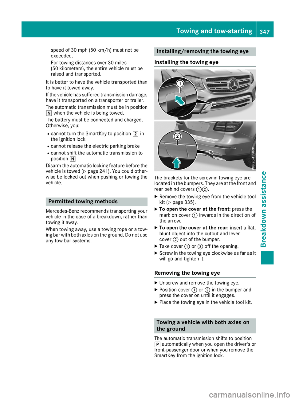
Installing the towing eye The brackets for the screw-in towing eye are
located in the bumpers. They are at the front and
rear behind covers 00430044.
X Remove the towing eye from the vehicle tool
kit (Y page 335).
X To open the cover at the front: press the
mark on cover 0043inwards in the direction of
the arrow.
X To open the cover at the rear: insert a flat,
blunt object into the cutout and lever
cover 0044out of the bumper.
X Take cover 0043or0044 off the opening.
X Screw in the towing eye clockwise as far as it
will go and tighten it.
Removing the towing eye X
Unscrew and remove the towing eye.
X Position cover 0043or0044 in the bumper and
press the cover on until it engages.
X Place the towing eye in the vehicle tool kit. Towing a vehicle with both axles on
the ground
The automatic transmission shifts to position
005D automatically when you open the driver's or
front-passenger door or when you remove the
SmartKey from the ignition lock. Towing and tow-starting
347Breakdown assistance Z
Page 350 of 398
In order to ensure that the automatic transmis-
sion stays in position 005Cwhen towing away the
vehicle, you must observe the following points:
X Make sure that the vehicle is stationary.
X Turn the SmartKey to position 0048in the igni-
tion lock.
X Depress and hold the brake pedal.
X Shift the automatic transmission to position
005C.
X Leave the SmartKey in position 0048in the igni-
tion lock.
X Release the brake pedal.
X Release the electric parking brake.
X Switch on the hazard warning lamps
(Y page 117).
In order to signal a change of direction when
towing the vehicle with the hazard warning
lamps switched on, use the combination switch as usual. In this case, only the indicator lamps
for the direction of travel flash. After resetting
the combination switch, the hazard warning
lamp starts flashing again. Transporting the vehicle
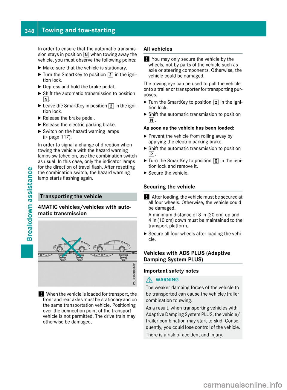
4MATIC vehicles/vehicles with auto-
matic transmission !
When the vehicle is loaded for transport, the
front and rear axles must be stationary and on
the same transportation vehicle. Positioning
over the connection point of the transport
vehicle is not permitted. The drive train may
otherwise be damaged. All vehicles !
You may only secure the vehicle by the
wheels, not by parts of the vehicle such as
axle or steering components. Otherwise, the
vehicle could be damaged.
The towing eye can be used to pull the vehicle
onto a trailer or transporter for transporting pur-
poses.
X Turn the SmartKey to position 0048in the igni-
tion lock.
X Shift the automatic transmission to position
005C.
As soon as the vehicle has been loaded:
X Prevent the vehicle from rolling away by
applying the electric parking brake.
X Shift the automatic transmission to position
005D.
X Turn the SmartKey to position 0092in the igni-
tion lock and remove it.
X Secure the vehicle.
Securing the vehicle !
After loading, the vehicle must be secured at
all four wheels. Otherwise, the vehicle could
be damaged.
A minimum distance of 8 in (20 cm) up and
4 in (10 cm) down must be maintained to the transport platform.
X Secure all four wheels after loading the vehi-
cle.
Vehicles with ADS PLUS (Adaptive
Damping System PLUS) Important safety notes
G
WARNING
The weaker damping forces of the vehicle to
be transported can cause the vehicle/trailer
combination to swing.
As a result, when transporting vehicles with
Adaptive Damping System PLUS, the vehicle/ trailer combination may start to skid. Conse-
quently, you could lose control of the vehicle.
There is a risk of accident and injury. 348
Towing and tow-startingBreakdown assistance
Page 351 of 398
When transporting, make sure that:
R the vehicle is has been loaded onto the
transporter correctly
R the vehicle is secured at all four wheels with
suitable tensioning straps
R you do not exceed the maximum permissi-
ble speed of 35 mph (60 km/h)
Securing the vehicle ! After loading, the vehicle must be secured at
all four wheels. Otherwise, the vehicle could
be damaged.
A minimum distance of 8 in (20 cm) up and
4 in (10 cm) down must be maintained to the
transport platform.
X Secure all four wheels after loading the vehi-
cle. Information on 4MATIC vehicles
! Vehicles with 4MATIC must not be towed
with either the front or the rear axle raised, as
doing so will damage the transmission.
Vehicles with 4MATIC may either be towed away with both axles on the ground or be loaded up
and transported.
If the vehicle's transmission, front, or rear axle is
damaged, have the vehicle transported on a
truck or trailer.
In the event of damage to the electrical sys-
tem: if the battery is defective, the automatic
transmission will be locked in position 005D. To
shift the automatic transmission to position 005C,
you must provide power to the vehicle's on-
board electrical system in the same way as
when jump-starting (Y page 343).
Have the vehicle transported on a transporter or
trailer. Tow-starting (emergency engine
starting)
! Vehicles with automatic transmission must
not be tow-started. You could otherwise dam- age the automatic transmission.
You can find information on "Jump-starting"
under (Y page 343). Fuses
Important safety notes
G
WARNING
If you manipulate or bridge a faulty fuse or if
you replace it with a fuse with a higher amper- age, the electric cables could be overloaded.
This could result in a fire. There is a risk of an
accident and injury.
Always replace faulty fuses with the specified
new fuses having the correct amperage.
! For the fuse boxes in the engine compart-
ment and under the rear bench seat, only use fuses with the suffix "S". Otherwise, compo-
nents or systems could be damaged.
! Make sure that no moisture can enter the
fuse box when the cover is open.
! When closing the cover, make sure that it is
lying correctly on the fuse box. Moisture seep-
ing in or dirt could otherwise impair the oper- ation of the fuses.
The fuses in your vehicle serve to close down
faulty circuits. If a fuse blows, all the compo-
nents on the circuit and their functions stop
operating.
Blown fuses must be replaced with fuses of the
same rating, which you can recognize by the
color and value. The fuse ratings are listed in the fuse allocation chart.
The fuse allocation chart is located in the fuse
box under the rear bench seat (Y page 350).
If a newly inserted fuse also blows, have the
cause traced and rectified at a qualified special- ist workshop, e.g. an authorized Mercedes-Benz
Center. Before changing a fuse
Observe the important safety notes
(Y page 349)
X Switch off the engine.
X Switch off all electrical consumers. Fuses
349Breakdown assistance Z
Page 366 of 398
i
The specifications shown on the Tire and
Loading Information placard in the illustration
are examples. The number of seats is vehicle- specific and can differ from the details shown.
The number of seats in your vehicle can be
found on the Tire and Loading Information
placard. Determining the correct load limit
Step-by-step instructions The following steps have been developed as
required of all manufacturers under Title 49,
Code of U.S. Federal Regulations, Part 575 pur- suant to the "National Traffic and Motor Vehicle
Safety Act of 1966".
X Step 1: Locate the statement "The combined
weight of occupants and cargo should never exceed XXX kg or XXX lbs." on your vehicle’s
Tire and Loading Information placard.
X Step 2: Determine the combined weight of
the driver and passengers that will be riding in your vehicle.
X Step 3: Subtract the combined weight of the
driver and passengers from XXX kilograms or
XXX lbs.
X Step 4: The resulting figure equals the avail-
able amount of cargo and luggage load capa-
city. For example, if the "XXX" amount equals 1400 lbs and there will be five 150-lb pas-
sengers in your vehicle, the amount of avail-
able cargo and luggage load capacity is
650 lbs (1400 - 750 (5 x 150) = 650 lbs).
X Step 5: Determine the combined weight of
luggage and cargo being loaded on the vehi-
cle. That weight may not safely exceed the
available cargo and luggage load capacity cal- culated in step 4. Example: steps 1 to 3
The following table shows examples on how to calculate total and cargo load capacities with varying seating configurations and number and size of occupants. The following examples use a load limit of
1500 lbs (680 kg). This is for illustration purposes only. Make sure you are using the actual load
limit for your vehicle stated on your vehicle's Tire and Loading Information placard (Y page 362).
The greater the combined weight of the occupants, the lower the maximum luggage load.
Additional information when towing a trailer (Y page 222).
Step 1 Example 1 Example 2 Example 3
Combined maximum
weight of occupants
and cargo (data from
the Tire and Loading
Information placard)
1500 lbs (680 kg) 1500 lbs (680 kg) 1500 lbs (680 kg)
Step 2
Example 1 Example 2 Example 3
Number of people in
the vehicle (driver and
occupants)
5 3 1
Distribution of the
occupants
Front: 2
Rear: 3 Front: 1
Rear: 2 Front: 1364
Loading the vehicleWheels and tires
Page 374 of 398
PSI (pounds per square inch)
A standard unit of measure for tire pressure.
Aspect ratio
Relationship between tire height and tire width
in percent.
Tire pressure
This is pressure inside the tire applying an out-
ward force to each square inch of the tire's sur-
face. The tire pressure is specified in pounds per
square inch (psi), in kilopascal (kPa) or in bar.
The tire pressure should only be corrected when
the tires are cold.
Cold tire pressure
The tires are cold:
R if the vehicle has been parked with the tires
out of direct sunlight for at least three hours
and
R if the vehicle has not been driven further than
1 mile (1.6 km)
Tread
The part of the tire that comes into contact with
the road.
BeadThe tire bead ensures that the tire sits securely
on the wheel. There are several steel wires in the
bead to prevent the tire from coming loose from the wheel rim.
Sidewall The part of the tire between the tread and the
bead.
Weight of optional extras The combined weight of those optional extras
that weigh more than the replaced standard
parts and more than 2.3 kg (5 lbs). These
optional extras, such as high-performance
brakes, level control, a roof rack or a high-per-
formance battery, are not included in the curb
weight and the weight of the accessories.
TIN (Tire Identification Number) This is a unique identifier which can be used by
a tire manufacturer to identify tires, for example for a product recall, and thus identify the pur-
chasers. The TIN is made up of the manufactur-
er's identity code, tire size, tire type code and
the manufacturing date. Load bearing index
The load bearing index (also load index) is a code that contains the maximum load bearing capa-
city of a tire.
Traction
Traction is the result of friction between the tires and the road surface.
TWR (Tongue Weight Rating)
The TWR specifies the maximum permissible
weight that the ball coupling of the trailer tow
hitch can support.
Treadwear indicators Narrow bars (tread wear bars) that are distrib-
uted over the tire tread. If the tire tread is level
with the bars, the wear limit of 00CDin (1.6 mm)
has been reached.
Occupant distribution
The distribution of occupants in a vehicle at their designated seating positions.
Total load limit Nominal load and luggage load plus 68 kg
(150 lbs) multiplied by the number of seats in
the vehicle. Changing a wheel
Flat tire
The "Breakdown assistance" section
(Y page 335) contains information and notes on
how to deal with a flat tire. Information on driv-
ing with MOExtended tires in the event of a flat
tire can be found under "MOExtended tires (tires with run-flat characteristics" (Y page 336).
Vehicles with an emergency spare wheel: in
the event of a flat tire, mount the emergency
spare wheel according to the description under "Mounting a wheel" (Y page 373). Rotating the wheels
G
WARNING
Rotating the front and rear wheels if the
wheels or tires have different dimensions may severely impair the driving characteristics.
The service brake or wheel suspension com- 372
Changing a wheelWheels and tires
Page 379 of 398
Lowering the vehicle
G
WARNING
The wheels could come loose if the wheel
bolts or wheel nuts are not tightened to the
prescribed tightening torque. There is a risk of an accident.
Ensure that the wheel bolts or wheel nuts are tightened to the prescribed tightening torque.
If you are not sure, do not move the vehicle.
Contact a qualified specialist workshop and
have the tightening torque checked immedi-
ately.
! Mercedes-AMG vehicles with a collapsi-
ble spare wheel: before lowering the vehicle,
inflate the collapsible spare wheel with the
tire inflation compressor. The wheel rim could
otherwise be damaged.
X Place the ratchet wrench onto the hexagon
nut of the jack so that the letters ABare visi-
ble.
X Turn the ratchet wrench until the vehicle is
once again standing firmly on the ground.
X Place the jack to one side. X
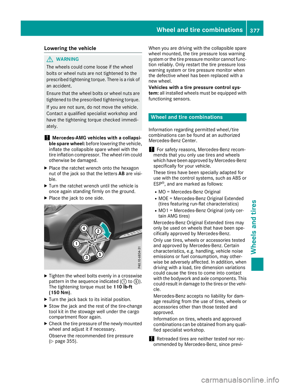
Tighten the wheel bolts evenly in a crosswise
pattern in the sequence indicated (0043 to0083).
The tightening torque must be 110 lb-ft
(150 Nm) .
X Turn the jack back to its initial position.
X Stow the jack and the rest of the tire-change
tool kit in the stowage well under the cargo
compartment floor again.
X Check the tire pressure of the newly mounted
wheel and adjust it if necessary.
Observe the recommended tire pressure
(Y page 355). When you are driving with the collapsible spare
wheel mounted, the tire pressure loss warning
system or the tire pressure monitor cannot func- tion reliably. Only restart the tire pressure loss
warning system or tire pressure monitor when
the defective wheel has been replaced with a
new wheel.
Vehicles with a tire pressure control sys-
tem: all installed wheels must be equipped with
functioning sensors. Wheel and tire combinations
Information regarding permitted wheel/tire
combinations can be found at an authorized
Mercedes-Benz Center.
! For safety reasons, Mercedes-Benz recom-
mends that you only use tires and wheels
which have been approved by Mercedes-Benz specifically for your vehicle.
These tires have been specially adapted for
use with the control systems, such as ABS or
ESP ®
, and are marked as follows:
R MO = Mercedes-Benz Original
R MOE = Mercedes-Benz Original Extended
(tires featuring run-flat characteristics)
R MO1 = Mercedes-Benz Original (only cer-
tain AMG tires)
Mercedes-Benz Original Extended tires may
only be used on wheels that have been spe-
cifically approved by Mercedes-Benz.
Only use tires, wheels or accessories tested
and approved by Mercedes-Benz. Certain
characteristics, e.g. handling, vehicle noise
emissions or fuel consumption, may other-
wise be adversely affected. In addition, when
driving with a load, tire dimension variations
could cause the tires to come into contact
with the bodywork and axle components. This
could result in damage to the tires or the vehi- cle.
Mercedes-Benz accepts no liability for dam-
age resulting from the use of tires, wheels or
accessories other than those tested and
approved.
Information on tires, wheels and approved
combinations can be obtained from any quali-fied specialist workshop.
! Retreaded tires are neither tested nor rec-
ommended by Mercedes-Benz, since previ- Wheel and tire combinations
377Wheels and tires Z