2019 MERCEDES-BENZ GLS tow bar
[x] Cancel search: tow barPage 24 of 398
Display message ............................ 268
Distribution of the vehicle occu-
pants (definition) ............................ 372
DOT (Department of Transporta-
tion) (definition) ............................. 370
DOT, Tire Identification Number
(TIN) ............................................... 370
GAWR (Gross Axle Weight Rating)
(definition) .................................... .371
GTW (Gross Trailer Weight) (defi-
nition) ............................................ 371
GVW (Gross Vehicle Weight) (def-
inition) .......................................... .371
GVWR (Gross Vehicle Weight Rat-
ing) (definition) .............................. 371
Important safety notes .................. 352
Increased vehicle weight due to
optional equipment (definition) ...... 371
Information on driving .................... 352
Kilopascal (kPa) (definition) ........... 371
Labeling (overview )........................ 367
Load bearing index (definition) ...... 372
Load index ..................................... 369
Load index (definition) ................... 371
M+S tire s....................................... 354
Maximum load on a tire (defini-
tion) ............................................... 371
Maximum loaded vehicle weight
(definition) ..................................... 371
Maximum permissible tire pres-
sure (definition) ............................. 371
Maximum tire load ......................... 369
Maximum tire load (definition) ....... 371
MOExtended tire s.......................... 353
Optional equipment weight (defi-
nition) ............................................ 372
PSI (pounds per square inch) (def-
inition) ........................................... 372
Replacing ....................................... 372
Service life ..................................... 353
Sidewall (definition) ....................... 372
Snow chains .................................. 354
Speed rating (definition) ................ 371
Storing ........................................... 373
Structure and characteristics
(definition) ..................................... 370
Summer tires in winter .................. 354
Temperature .................................. 366 TIN (Tire Identification Number)
(definition) ..................................... 372
Tire bead (definition) ...................... 372
Tire pressure (definition) ................ 372
Tire pressures (recommended) ...... 371
Tire size (data) ............................... 377
Tire size designation, load-bearing
capacity, speed rating .................... 367
Tire tread ....................................... 353
Tire tread (definition) ..................... 372
Total load limit (definition) ............. 372
Traction ......................................... 366
Traction (definition) ....................... 372
Tread wear ..................................... 366
TWR (permissible trailer drawbar
noseweight) (definition) ................. 372
Uniform Tire Quality Grading
Standards ...................................... 366
Uniform Tire Quality Grading
Standards (definition) .................... 370
Wear indicator (definition) ............. 372
Wheel and tire combination ........... 377
Wheel rim (definition) .................... 371
see Flat tire
Tool
see Vehicle tool kit
Top Tether ............................................ 63
Tow-starting
Emergency engine starting ............ 349
Important safety notes .................. 346
Towing
Permitted towing methods ............ 347
Towing a trailer
Axle load, permissibl e.................... 392
Cleaning the trailer tow hitch ......... 331
Coupling up a traile r...................... 224
Decoupling a trailer ....................... 226
Driving tip s.................................... 222
Important safety notes .................. 221
Installing the ball coupling ............. 223
Lights display message .................. 257
Mounting dimensions .................... 392
Parking Assist PARKTRONIC .......... 189
Power supply ................................. 227
Pulling away with a traile r.............. 143
Removing the ball coupling ............ 226
Trailer load s................................... 392 22
Index
Page 25 of 398
Towing away
Important safety guidelines ........... 346
Installing the towing eye ................ 347
Notes for 4MATIC vehicles ............ 349
Removing the towing eye ............... 347
Transporting the vehicle ................ 348
With both axles on the ground ....... 347
Towing eye ......................................... 335
Traffic reports
see also Digital Operator's Man-
ual .................................................. 287
Traffic Sign Assist
Activating/deactivating the warn-ing function .................................... 238
Display message ............................ 264
Function/note s............................. 206
Important safety notes .................. 206
Instrument cluster display ............. 206
Trailer coupling
see Towing a trailer
Trailer loads and drawbar nose-
weights ............................................... 226
Trailer towing
Active Blind Spot Assist ................. 212
Active Lane Keeping Assist ............ 215
Blind Spot Assist ............................ 208
Permissible trailer loads and
drawbar noseweights ..................... 226
Transfer case ..................................... 155
Transmission
see Automatic transmission
Transmission position display ......... 149
Transporting the vehicle .................. 348
Traveling uphill
Brow of hill ..................................... 170
Driving downhill ............................. 170
Maximum gradient-climbing capa-
bility ............................................... 170
Trim pieces (cleaning instruc-
tions) .................................................. 332
Trip computer (on-board com-
puter) .................................................. 233
Trip odometer
Calling up ....................................... 233
Resetting (on-board computer) ...... 234
Trunk
see Tailgate Turn signals
Display message ............................ 257
Replacing bulbs (front) ................... 122
Switching on/of f........................... 116
Two-way radio
Frequencies ................................... 382
Installation ..................................... 382
Transmission output (maximum) .... 382
TWR (Tongue Weight Rating) (defi-
nition) ................................................. 372
Type identification plate
see Vehicle identification plate U
Unlocking Emergency unlocking ....................... 84
From inside the vehicle (central
unlocking button) ............................. 83
Upshift indicator (on-board com-
puter, Mercedes-AMG vehicles) ....... 242
USB devices
Connecting to the Media Inter-
face ............................................... 294 V
Vanity mirror (in the sun visor) ........ 305
Vehicle
Correct use ...................................... 31
Data acquisition ............................... 32
Display message ............................ 270
Equipment ....................................... 28
Individual settings .......................... 240
Limited Warranty ............................. 32
Loading .......................................... 362
Locking (in an emergency) ............... 84
Locking (SmartKey) .......................... 77
Lowering ........................................ 377
Maintenance .................................... 29
Operating safety .............................. 30
Parking .......................................... 158
Parking for a long period ................ 160
Pulling away ................................... 143
Raising ........................................... 374
REACH Regulation ........................... 31
Reporting problems ......................... 32
Securing from rolling away ............ 374 Index
23
Page 191 of 398
Sport mode
The firmer suspension setting in the Sport drive
program ensures even better contact with the
road. Select this mode when employing a sporty
driving style, e.g. on winding country roads.
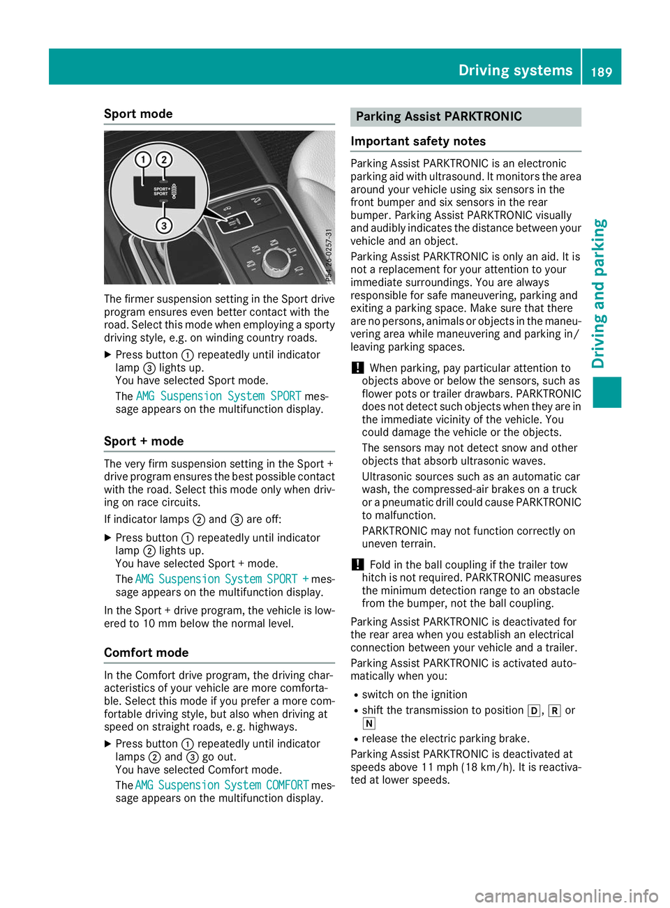
X Press button 0043repeatedly until indicator
lamp 0087lights up.
You have selected Sport mode.
The AMG Suspension System SPORT AMG Suspension System SPORT mes-
sage appears on the multifunction display.
Sport + mode The very firm suspension setting in the Sport +
drive program ensures the best possible contact
with the road. Select this mode only when driv-
ing on race circuits.
If indicator lamps 0044and 0087are off:
X Press button 0043repeatedly until indicator
lamp 0044lights up.
You have selected Sport + mode.
The AMG AMG Suspension
Suspension System
SystemSPORT +
SPORT + mes-
sage appears on the multifunction display.
In the Sport + drive program, the vehicle is low-
ered to 10 mm below the normal level.
Comfort mode In the Comfort drive program, the driving char-
acteristics of your vehicle are more comforta-
ble. Select this mode if you prefer a more com-
fortable driving style, but also when driving at
speed on straight roads, e. g. highways.
X Press button 0043repeatedly until indicator
lamps 0044and 0087go out.
You have selected Comfort mode.
The AMG
AMG Suspension Suspension System
SystemCOMFORT
COMFORT mes-
sage appears on the multifunction display. Parking Assist PARKTRONIC
Important safety notes Parking Assist PARKTRONIC is an electronic
parking aid with ultrasound. It monitors the area
around your vehicle using six sensors in the
front bumper and six sensors in the rear
bumper. Parking Assist PARKTRONIC visually
and audibly indicates the distance between your
vehicle and an object.
Parking Assist PARKTRONIC is only an aid. It is
not a replacement for your attention to your
immediate surroundings. You are always
responsible for safe maneuvering, parking and
exiting a parking space. Make sure that there
are no persons, animals or objects in the maneu- vering area while maneuvering and parking in/
leaving parking spaces.
! When parking, pay particular attention to
objects above or below the sensors, such as
flower pots or trailer drawbars. PARKTRONIC does not detect such objects when they are in
the immediate vicinity of the vehicle. You
could damage the vehicle or the objects.
The sensors may not detect snow and other
objects that absorb ultrasonic waves.
Ultrasonic sources such as an automatic car
wash, the compressed-air brakes on a truck
or a pneumatic drill could cause PARKTRONIC to malfunction.
PARKTRONIC may not function correctly on
uneven terrain.
! Fold in the ball coupling if the trailer tow
hitch is not required. PARKTRONIC measures
the minimum detection range to an obstacle
from the bumper, not the ball coupling.
Parking Assist PARKTRONIC is deactivated for
the rear area when you establish an electrical
connection between your vehicle and a trailer.
Parking Assist PARKTRONIC is activated auto-
matically when you:
R switch on the ignition
R shift the transmission to position 005B,005Eor
005C
R release the electric parking brake.
Parking Assist PARKTRONIC is deactivated at
speeds above 11 mph (18 km/h). It is reactiva- ted at lower speeds. Driving systems
189Driving and parking Z
Page 199 of 398
R
if the camera lens is dirty or obstructed.
Observe the notes on cleaning
(Y page 330)
R if the rear of your vehicle is damaged. In this
event, have the camera position and setting
checked at a qualified specialist workshop
The field of vision and other functions of the rear
view camera may be restricted due to additional
accessories on the rear of the vehicle (e.g.
license plate holder, bicycle rack).
On vehicles with height-adjustable chassis,
leaving the standard height can result in inac-
curacies in the guide lines, depending on tech-
nical conditions.
i The contrast of the display may be affected
by the sudden presence of sunlight or other
light sources, e.g. when exiting a garage. Pay
particular attention in this situation.
i If usability is severely restricted, e.g. due to
pixel errors, have the display repaired or
replaced.
i The rear view camera is protected from rain-
drops and dust by means of a flap. When the
rear view camera is activated, this flap opens.
The flap closes again when:
R you have finished the maneuvering process
R you switch off the engine
R you open the cargo compartment
Observe the notes on cleaning (Y page 330).
For technical reasons, the flap may remain
open briefly after the rear view camera has
been deactivated.
Activating/deactivating the rear view
camera X
To activate: make sure that the SmartKey is
in position 0048in the ignition lock.
X Make sure that the Activation by R gear
Activation by R gear
function is selected on the multimedia system (see the Digital Operator's Manual).
X Engage reverse gear.
The rear view camera flap opens. The multi-
media system shows the area behind the vehi-
cle with guide lines.
The image from the rear view camera is avail- able throughout the maneuvering process.
X To switch the function mode for vehicles
with trailer tow hitch: using the controller,
select symbol 0043for the "Reverse parking" function or symbol
0044for "Coupling up a
trailer".
The symbol of the selected function is high-
lighted.
To deactivate: shift the transmission to posi-
tion 005Dor drive forwards.
Displays in the multimedia system The rear view camera may show a distorted view
of obstacles, show them incorrectly or not at all.
The rear view camera does not show objects in
the following positions:
R very close to the rear bumper
R under the rear bumper
R in the area immediately above the tailgate
handle
! Objects not at ground level may appear to
be further away than they actually are, e.g.:
R the bumper of a parked vehicle
R the drawbar of a trailer
R the ball coupling of a trailer tow hitch
R the rear section of an HGV
R a slanted post
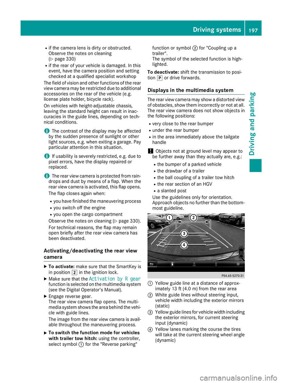
Use the guidelines only for orientation.
Approach objects no further than the bottom-
most guideline. 0043
Yellow guide line at a distance of approx-
imately 13 ft (4.0 m) from the rear area
0044 White guide lines without steering input,
vehicle width including the exterior mirrors
(static)
0087 Yellow guide lines for vehicle width including
the exterior mirrors, for current steering
input (dynamic)
0085 Yellow lanes marking the course the tires
will take at the current steering wheel angle
(dynamic) Driving systems
197Driving and parking Z
Page 202 of 398
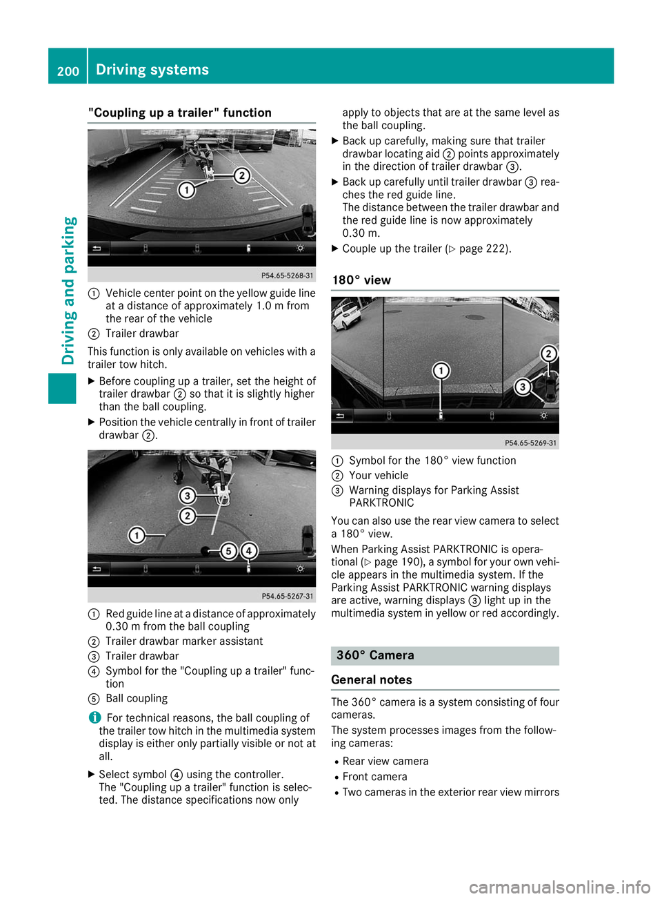
"Coupling up a trailer" function
0043
Vehicle center point on the yellow guide line
at a distance of approximately 1.0 m from
the rear of the vehicle
0044 Trailer drawbar
This function is only available on vehicles with a
trailer tow hitch.
X Before coupling up a trailer, set the height of
trailer drawbar 0044so that it is slightly higher
than the ball coupling.
X Position the vehicle centrally in front of trailer
drawbar 0044. 0043
Red guide line at a distance of approximately
0.30 m from the ball coupling
0044 Trailer drawbar marker assistant
0087 Trailer drawbar
0085 Symbol for the "Coupling up a trailer" func-
tion
0083 Ball coupling
i For technical reasons, the ball coupling of
the trailer tow hitch in the multimedia system
display is either only partially visible or not at all.
X Select symbol 0085using the controller.
The "Coupling up a trailer" function is selec-
ted. The distance specifications now only apply to objects that are at the same level as
the ball coupling.
X Back up carefully, making sure that trailer
drawbar locating aid 0044points approximately
in the direction of trailer drawbar 0087.
X Back up carefully until trailer drawbar 0087rea-
ches the red guide line.
The distance between the trailer drawbar and the red guide line is now approximately
0.30 m.
X Couple up the trailer (Y page 222).
180° view 0043
Symbol for the 180° view function
0044 Your vehicle
0087 Warning displays for Parking Assist
PARKTRONIC
You can also use the rear view camera to select
a 180° view.
When Parking Assist PARKTRONIC is opera-
tional (Y page 190), a symbol for your own vehi-
cle appears in the multimedia system. If the
Parking Assist PARKTRONIC warning displays
are active, warning displays 0087light up in the
multimedia system in yellow or red accordingly. 360° Camera
General notes The 360° camera is a system consisting of four
cameras.
The system processes images from the follow-
ing cameras:
R Rear view camera
R Front camera
R Two cameras in the exterior rear view mirrors 200
Driving systemsDriving and parking
Page 204 of 398
Guide lines are always shown at road level. In
trailer mode, the guide lines are shown at the
level of the trailer coupling.
The field of vision and other functions of the
camera system may be restricted due to addi-
tional accessories on the rear of the vehicle (e.g.
license plate holder, bicycle rack).
On vehicles with height-adjustable chassis,
depending on technical conditions, leaving the
standard height can result in:
R inaccuracies in the guide lines
R inaccuracies in the display of generated
images (top view)
Activation conditions The 360° camera image can be displayed in the
following situations:
R your vehicle is equipped with a 360° camera
R the SmartKey is in key position 0048in the igni-
tion lock
R the multimedia system is switched on
Switching on the 360° camera X
Press the 00D4button in the center console
for longer than two seconds.
Depending on whether transmission position
005B or005E is selected, the following appears:
R a split screen with top view and the image
from the front camera or
R a split screen with top view and the image
from the rear view camera
or
X Press the 00D4button in the center console.
The vehicle menu is displayed.
X Select 360°
360° Camera Camera and press 7to confirm.
Depending on whether transmission position
005B or005E is selected, the following appears:
R a split screen with top view and the image
from the front camera or
R a split screen with top view and the image
from the rear view camera
Activating the 360° camera using
reverse gear The 360° camera images can be automatically
displayed by engaging reverse gear. X
Make sure that the SmartKey is in position 0048
in the ignition lock.
X Make sure that the Activation by R gear Activation by R gear
function is selected on the multimedia system (see the Digital Operator's Manual).
X To show the 360° camera image: engage
reverse gear.
The multimedia system shows the area
behind the vehicle in split-screen mode. You
see the top view of the vehicle and the image from the rear view camera.
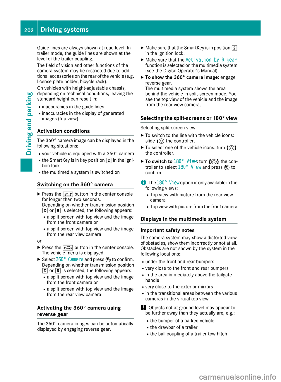
Selecting the split-screens or 180° view Selecting split-screen view
X To switch to the line with the vehicle icons:
slide 5the controller.
X To select one of the vehicle icons: turn 3
the controller.
X To switch to 180° View
180° View :turn 3 the con-
troller to select 180° View
180° View and press7to
confirm.
i The
180° 180° View
Viewoption is only available in the
following views:
R Top view with picture from the rear view
camera
R Top view with picture from the front camera
Displays in the multimedia system Important safety notes
The camera system may show a distorted view
of obstacles, show them incorrectly or not at all. Obstacles are not shown by the system in the
following locations:
R under the front and rear bumpers
R very close to the front and rear bumpers
R in the area immediately above the tailgate
handle
R very close to the exterior mirrors
R in the transitional areas between the various
cameras in the virtual top view
! Objects not at ground level may appear to
be further away than they actually are, e.g.:
R the bumper of a parked vehicle
R the drawbar of a trailer
R the ball coupling of a trailer tow hitch 202
Driving systemsDriving and parking
Page 206 of 398
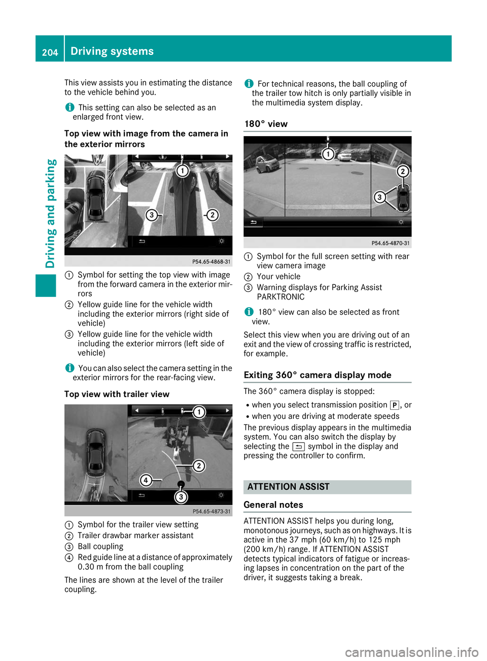
This view assists you in estimating the distance
to the vehicle behind you.
i This setting can also be selected as an
enlarged front view.
Top view with image from the camera in
the exterior mirrors 0043
Symbol for setting the top view with image
from the forward camera in the exterior mir-
rors
0044 Yellow guide line for the vehicle width
including the exterior mirrors (right side of
vehicle)
0087 Yellow guide line for the vehicle width
including the exterior mirrors (left side of
vehicle)
i You can also select the camera setting in the
exterior mirrors for the rear-facing view.
Top view with trailer view 0043
Symbol for the trailer view setting
0044 Trailer drawbar marker assistant
0087 Ball coupling
0085 Red guide line at a distance of approximately
0.30 m from the ball coupling
The lines are shown at the level of the trailer
coupling. i
For technical reasons, the ball coupling of
the trailer tow hitch is only partially visible in
the multimedia system display.
180° view 0043
Symbol for the full screen setting with rear
view camera image
0044 Your vehicle
0087 Warning displays for Parking Assist
PARKTRONIC
i 180° view can also be selected as front
view.
Select this view when you are driving out of an
exit and the view of crossing traffic is restricted,
for example.
Exiting 360° camera display mode The 360° camera display is stopped:
R
when you select transmission position 005D, or
R when you are driving at moderate speeds
The previous display appears in the multimedia
system. You can also switch the display by
selecting the 0039symbol in the display and
pressing the controller to confirm. ATTENTION ASSIST
General notes ATTENTION ASSIST helps you during long,
monotonous journeys, such as on highways. It is
active in the 37 mph (60 km/h) to 125 mph
(200 km/h) range. If ATTENTION ASSIST
detects typical indicators of fatigue or increas-
ing lapses in concentration on the part of the
driver, it suggests taking a break. 204
Driving systemsDriving and parking
Page 210 of 398
If the lanes are narrow, vehicles driving in the
lane beyond the lane next to your vehicle may be
indicated, especially if the vehicles are not driv-
ing in the middle of their lane. This may be the
case if there are vehicles driving at the inner
edge of their lanes.
Due to the nature of the system:
R warnings may be issued in error when driving
close to crash barriers or similar solid lane
borders.
R the warning is canceled when driving for an
extended period next to long vehicles, such as
trucks.
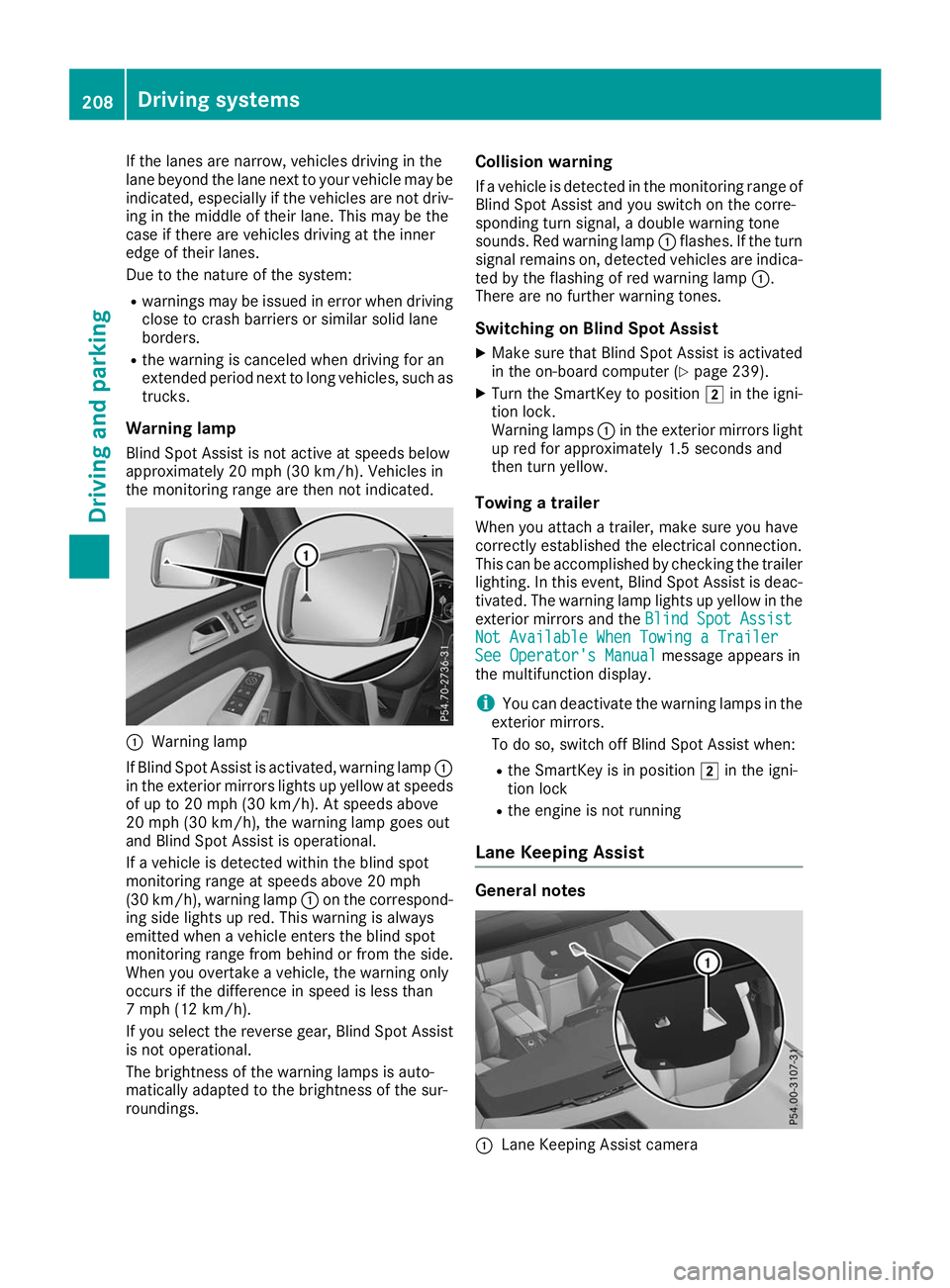
Warning lamp
Blind Spot Assist is not active at speeds below
approximately 20 mph (30 km/h). Vehicles in
the monitoring range are then not indicated. 0043
Warning lamp
If Blind Spot Assist is activated, warning lamp 0043
in the exterior mirrors lights up yellow at speeds
of up to 20 mph (30 km/h). At speeds above
20 mph (30 km/h), the warning lamp goes out
and Blind Spot Assist is operational.
If a vehicle is detected within the blind spot
monitoring range at speeds above 20 mph
(30 km/h), warning lamp 0043on the correspond-
ing side lights up red. This warning is always
emitted when a vehicle enters the blind spot
monitoring range from behind or from the side.
When you overtake a vehicle, the warning only
occurs if the difference in speed is less than
7 mph (12 km/h).
If you select the reverse gear, Blind Spot Assist
is not operational.
The brightness of the warning lamps is auto-
matically adapted to the brightness of the sur-
roundings. Collision warning
If a vehicle is detected in the monitoring range of
Blind Spot Assist and you switch on the corre-
sponding turn signal, a double warning tone
sounds. Red warning lamp 0043flashes. If the turn
signal remains on, detected vehicles are indica-
ted by the flashing of red warning lamp 0043.
There are no further warning tones.
Switching on Blind Spot Assist X Make sure that Blind Spot Assist is activated
in the on-board computer (Y page 239).
X Turn the SmartKey to position 0048in the igni-
tion lock.
Warning lamps 0043in the exterior mirrors light
up red for approximately 1.5 seconds and
then turn yellow.
Towing a trailer
When you attach a trailer, make sure you have
correctly established the electrical connection.
This can be accomplished by checking the trailer
lighting. In this event, Blind Spot Assist is deac-
tivated. The warning lamp lights up yellow in the
exterior mirrors and the Blind Spot Assist
Blind Spot Assist
Not Available When Towing a Trailer Not Available When Towing a Trailer
See Operator's Manual See Operator's Manual message appears in
the multifunction display.
i You can deactivate the warning lamps in the
exterior mirrors.
To do so, switch off Blind Spot Assist when:
R the SmartKey is in position 0048in the igni-
tion lock
R the engine is not running
Lane Keeping Assist General notes
0043
Lane Keeping Assist camera 208
Driving systemsDriving and parking