2019 MERCEDES-BENZ GLS tow bar
[x] Cancel search: tow barPage 348 of 398
Towing and tow-starting
Important safety notes
G
WARNING
Functions relevant to safety are restricted or
no longer available if:
R the engine is not running.
R the brake system or the power steering is
malfunctioning.
R there is a malfunction in the voltage supply
or the vehicle's electrical system.
If your vehicle is being towed, much more
force may be necessary to steer or brake.
There is a risk of an accident.
In such cases, use a tow bar. Before towing,
make sure that the steering moves freely. G
WARNING
When towing or tow-starting another vehicle
and its weight is greater than the permissible gross weight of your vehicle, the:
R the towing eye could detach itself
R the vehicle/trailer combination could roll-
over.
There is a risk of an accident.
When towing or tow-starting another vehicle,
its weight should not be greater than the per- missible gross weight of your vehicle.
Details on the permissible gross vehicle weight
of your vehicle can be found on the vehicle iden-
tification plate (Y page 383).
! When Active Brake Assist, Active Distance
Assist DISTRONIC or the HOLD function is
activated, the vehicle brakes automatically in
certain situations.
To avoid damage to the vehicle, deactivate
these systems in the following or similar sit-
uations:
R when towing the vehicle
R in the car wash
! Make sure that the electric parking brake is
released. If the electric parking brake is faulty,
visit a qualified specialist workshop. !
Only secure the tow rope or tow bar at the
towing eyes, or the trailer tow hitch, if availa-
ble. You could otherwise damage the vehicle.
! Observe the following points when towing
with a tow rope:
R Secure the tow rope on the same side on
both vehicles.
R Make sure that the tow rope is not longer
than legally permitted. Mark the tow rope in
the middle, e.g. with a white cloth
(11.8 x 11.8 in). This will make other road
users aware that a vehicle is being towed.
R Only secure the tow cable to the towing
eyes or, if available, to the trailer tow hitch.
R Observe the brake lamps of the towing
vehicle while driving. Always maintain a dis-
tance a distance so that the tow rope does not sag.
R Do not use steel cables or chains to tow
your vehicle. You could otherwise damage
the vehicle.
! Do not use the trailer tow hitch for recovery
or towing. Do not use the towing eye for
recovery. this could damage the vehicle. If in
doubt, have the vehicle recovered using a
crane.
! When towing, pull away slowly and
smoothly. Pull the towed vehicle as straight as possible and not at an acute angle. Excessive
tractive power could damage the vehicles.
When towing, it is preferable to use a rigid tow-
ing bar as opposed to a tow rope. A rigid towing bar helps to keep the tractive power low.
! When towing away vehicles with KEYLESS-
GO, use the key instead of the Start/Stop
button. The automatic transmission may oth-
erwise shift to position 005Dwhen you open the
driver's or front-passenger door, which could damage the transmission.
! Do not tow with sling-type equipment. This
could damage the vehicle.
! Vehicles with differential locks: make sure
the differential locks are in automatic mode.
When towing, the differential locks must not
be switched on. The transmission may other- wise be damaged.
! You may tow the vehicle for a maximum dis-
tance of 30 miles (50 kilometers). A towing 346
Towing and tow-startingBreakdown assistance
Page 349 of 398
speed of 30 mph (50 km/h) must not be
exceeded.
For towing distances over 30 miles
(50 kilometers), the entire vehicle must be
raised and transported.
It is better to have the vehicle transported than
to have it towed away.
If the vehicle has suffered transmission damage, have it transported on a transporter or trailer.
The automatic transmission must be in position
005C when the vehicle is being towed.
The battery must be connected and charged.
Otherwise, you:
R cannot turn the SmartKey to position 0048in
the ignition lock
R cannot release the electric parking brake
R cannot shift the automatic transmission to
position 005C
Disarm the automatic locking feature before the vehicle is towed (Y page 241). You could other-
wise be locked out when pushing or towing the
vehicle. Permitted towing methods
Mercedes-Benz recommends transporting your
vehicle in the case of a breakdown, rather than
towing it away.
When towing away, use a towing rope or a tow-
ing bar with both axles on the ground. Do not use any tow bar systems. Installing/removing the towing eye
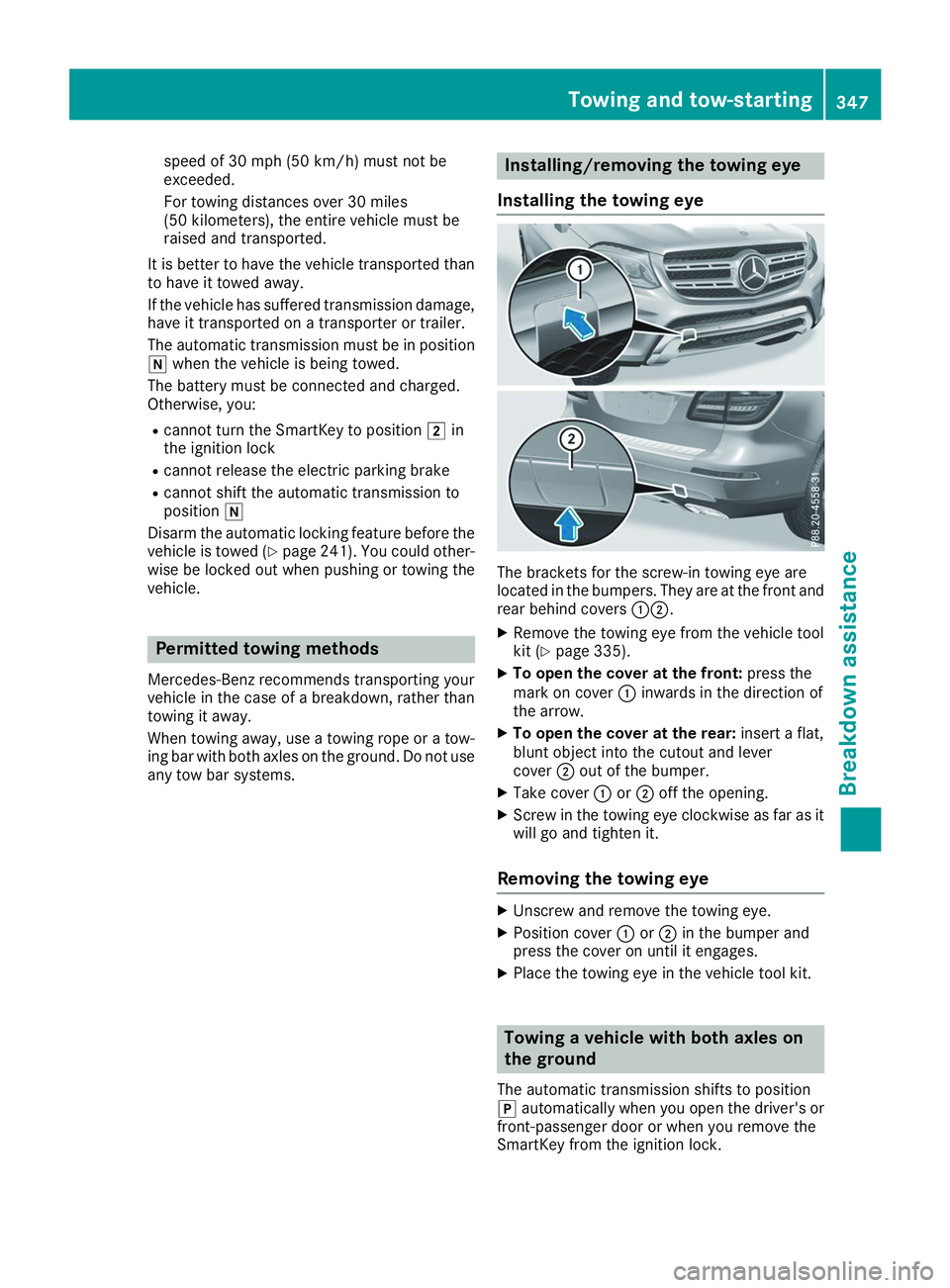
Installing the towing eye The brackets for the screw-in towing eye are
located in the bumpers. They are at the front and
rear behind covers 00430044.
X Remove the towing eye from the vehicle tool
kit (Y page 335).
X To open the cover at the front: press the
mark on cover 0043inwards in the direction of
the arrow.
X To open the cover at the rear: insert a flat,
blunt object into the cutout and lever
cover 0044out of the bumper.
X Take cover 0043or0044 off the opening.
X Screw in the towing eye clockwise as far as it
will go and tighten it.
Removing the towing eye X
Unscrew and remove the towing eye.
X Position cover 0043or0044 in the bumper and
press the cover on until it engages.
X Place the towing eye in the vehicle tool kit. Towing a vehicle with both axles on
the ground
The automatic transmission shifts to position
005D automatically when you open the driver's or
front-passenger door or when you remove the
SmartKey from the ignition lock. Towing and tow-starting
347Breakdown assistance Z
Page 374 of 398
PSI (pounds per square inch)
A standard unit of measure for tire pressure.
Aspect ratio
Relationship between tire height and tire width
in percent.
Tire pressure
This is pressure inside the tire applying an out-
ward force to each square inch of the tire's sur-
face. The tire pressure is specified in pounds per
square inch (psi), in kilopascal (kPa) or in bar.
The tire pressure should only be corrected when
the tires are cold.
Cold tire pressure
The tires are cold:
R if the vehicle has been parked with the tires
out of direct sunlight for at least three hours
and
R if the vehicle has not been driven further than
1 mile (1.6 km)
Tread
The part of the tire that comes into contact with
the road.
BeadThe tire bead ensures that the tire sits securely
on the wheel. There are several steel wires in the
bead to prevent the tire from coming loose from the wheel rim.
Sidewall The part of the tire between the tread and the
bead.
Weight of optional extras The combined weight of those optional extras
that weigh more than the replaced standard
parts and more than 2.3 kg (5 lbs). These
optional extras, such as high-performance
brakes, level control, a roof rack or a high-per-
formance battery, are not included in the curb
weight and the weight of the accessories.
TIN (Tire Identification Number) This is a unique identifier which can be used by
a tire manufacturer to identify tires, for example for a product recall, and thus identify the pur-
chasers. The TIN is made up of the manufactur-
er's identity code, tire size, tire type code and
the manufacturing date. Load bearing index
The load bearing index (also load index) is a code that contains the maximum load bearing capa-
city of a tire.
Traction
Traction is the result of friction between the tires and the road surface.
TWR (Tongue Weight Rating)
The TWR specifies the maximum permissible
weight that the ball coupling of the trailer tow
hitch can support.
Treadwear indicators Narrow bars (tread wear bars) that are distrib-
uted over the tire tread. If the tire tread is level
with the bars, the wear limit of 00CDin (1.6 mm)
has been reached.
Occupant distribution
The distribution of occupants in a vehicle at their designated seating positions.
Total load limit Nominal load and luggage load plus 68 kg
(150 lbs) multiplied by the number of seats in
the vehicle. Changing a wheel
Flat tire
The "Breakdown assistance" section
(Y page 335) contains information and notes on
how to deal with a flat tire. Information on driv-
ing with MOExtended tires in the event of a flat
tire can be found under "MOExtended tires (tires with run-flat characteristics" (Y page 336).
Vehicles with an emergency spare wheel: in
the event of a flat tire, mount the emergency
spare wheel according to the description under "Mounting a wheel" (Y page 373). Rotating the wheels
G
WARNING
Rotating the front and rear wheels if the
wheels or tires have different dimensions may severely impair the driving characteristics.
The service brake or wheel suspension com- 372
Changing a wheelWheels and tires
Page 379 of 398
Lowering the vehicle
G
WARNING
The wheels could come loose if the wheel
bolts or wheel nuts are not tightened to the
prescribed tightening torque. There is a risk of an accident.
Ensure that the wheel bolts or wheel nuts are tightened to the prescribed tightening torque.
If you are not sure, do not move the vehicle.
Contact a qualified specialist workshop and
have the tightening torque checked immedi-
ately.
! Mercedes-AMG vehicles with a collapsi-
ble spare wheel: before lowering the vehicle,
inflate the collapsible spare wheel with the
tire inflation compressor. The wheel rim could
otherwise be damaged.
X Place the ratchet wrench onto the hexagon
nut of the jack so that the letters ABare visi-
ble.
X Turn the ratchet wrench until the vehicle is
once again standing firmly on the ground.
X Place the jack to one side. X
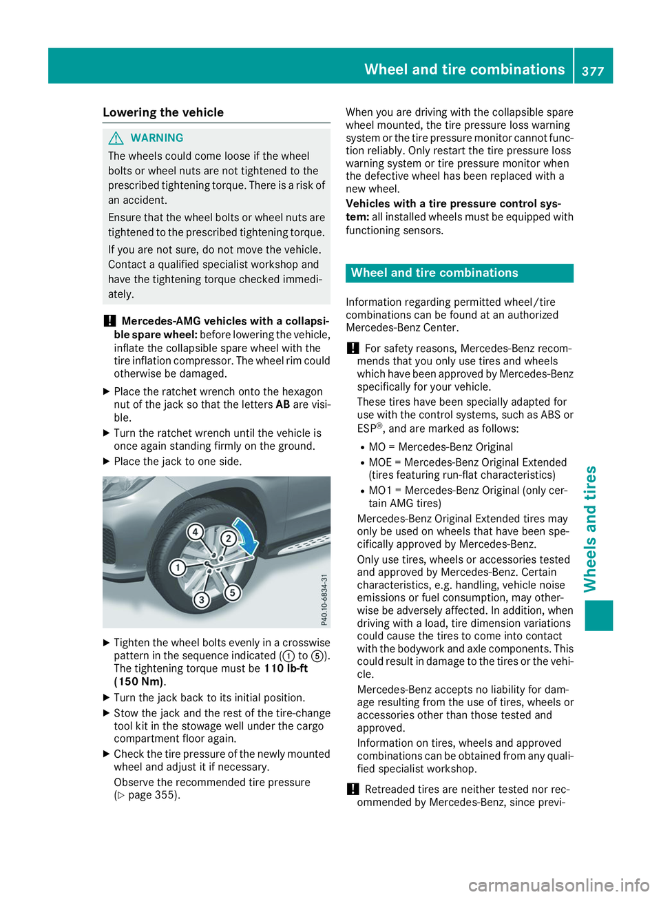
Tighten the wheel bolts evenly in a crosswise
pattern in the sequence indicated (0043 to0083).
The tightening torque must be 110 lb-ft
(150 Nm) .
X Turn the jack back to its initial position.
X Stow the jack and the rest of the tire-change
tool kit in the stowage well under the cargo
compartment floor again.
X Check the tire pressure of the newly mounted
wheel and adjust it if necessary.
Observe the recommended tire pressure
(Y page 355). When you are driving with the collapsible spare
wheel mounted, the tire pressure loss warning
system or the tire pressure monitor cannot func- tion reliably. Only restart the tire pressure loss
warning system or tire pressure monitor when
the defective wheel has been replaced with a
new wheel.
Vehicles with a tire pressure control sys-
tem: all installed wheels must be equipped with
functioning sensors. Wheel and tire combinations
Information regarding permitted wheel/tire
combinations can be found at an authorized
Mercedes-Benz Center.
! For safety reasons, Mercedes-Benz recom-
mends that you only use tires and wheels
which have been approved by Mercedes-Benz specifically for your vehicle.
These tires have been specially adapted for
use with the control systems, such as ABS or
ESP ®
, and are marked as follows:
R MO = Mercedes-Benz Original
R MOE = Mercedes-Benz Original Extended
(tires featuring run-flat characteristics)
R MO1 = Mercedes-Benz Original (only cer-
tain AMG tires)
Mercedes-Benz Original Extended tires may
only be used on wheels that have been spe-
cifically approved by Mercedes-Benz.
Only use tires, wheels or accessories tested
and approved by Mercedes-Benz. Certain
characteristics, e.g. handling, vehicle noise
emissions or fuel consumption, may other-
wise be adversely affected. In addition, when
driving with a load, tire dimension variations
could cause the tires to come into contact
with the bodywork and axle components. This
could result in damage to the tires or the vehi- cle.
Mercedes-Benz accepts no liability for dam-
age resulting from the use of tires, wheels or
accessories other than those tested and
approved.
Information on tires, wheels and approved
combinations can be obtained from any quali-fied specialist workshop.
! Retreaded tires are neither tested nor rec-
ommended by Mercedes-Benz, since previ- Wheel and tire combinations
377Wheels and tires Z
Page 394 of 398
Maximum gradient-climbing capabil-
ity
Note that the vehicle's gradient-climbing capa-
bility depends on the off-road conditions and the road surface conditions.
Missing values were not available at time of
going to print. Model Maximum gradient-
climbing capability Vehicles without
the Offroad Engi-
neering package
80%
Vehicles with the
Off-Road Engineer-
ing package
With LOW RANGE off-
road gear switched
on 100%
Mercedes-AMG
GLS 63 4MATIC
If the load on the front axle is reduced when
pulling away on a steep uphill slope, the front
wheels have a tendency to spin. Accelerate
carefully and make sure that the wheels do not
spin when driving on steep terrain.
For further information about the maximum gra- dient climbing ability, see (Y page 170).Trailer tow hitch
Mounting dimensions
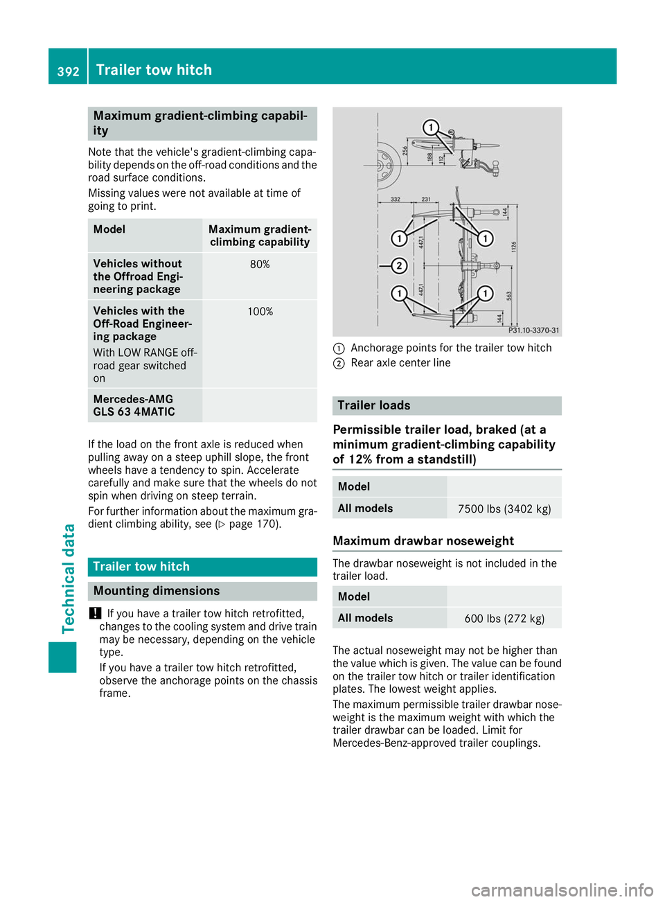
! If you have a trailer tow hitch retrofitted,
changes to the cooling system and drive train
may be necessary, depending on the vehicle
type.
If you have a trailer tow hitch retrofitted,
observe the anchorage points on the chassis
frame. 0043
Anchorage points for the trailer tow hitch
0044 Rear axle center line Trailer loads
Permissible trailer load, braked (at a
minimum gradient-climbing capability
of 12% from a standstill) Model
All models
7500 lbs (3402 kg)
Maximum drawbar noseweight
The drawbar noseweight is not included in the
trailer load.
Model
All models
600 lbs (272 kg)
The actual noseweight may not be higher than
the value which is given. The value can be found
on the trailer tow hitch or trailer identification
plates. The lowest weight applies.
The maximum permissible trailer drawbar nose-
weight is the maximum weight with which the
trailer drawbar can be loaded. Limit for
Mercedes-Benz-approved trailer couplings. 392
Trailer tow hitchTechnical data