2019 MERCEDES-BENZ GLS change wheel
[x] Cancel search: change wheelPage 227 of 398
Most U.S. states and all Canadian provinces
require by law:
R Safety chains between the towing vehicle and
the trailer. The chains should be cross-woundunder the trailer drawbar. They must be fas-
tened to the vehicle's trailer coupling, not to
the bumper or the axle.
Leave enough play in the chains to make tight
cornering possible.
R A separate brake system for certain types of
trailer.
R Safety switch for braked trailers. Check the
specific legal requirements applicable to your
state.
If the trailer becomes detached from the tow-
ing vehicle, the safety feature triggers the
trailer brakes. Towing a trailer
There are numerous legal requirements con-
cerning the towing of a trailer, e.g. speed restric-
tions. Make sure that your car/trailer combina- tion complies with the local regulations:
R in your place of residence
R in the location to which you are driving
The police and local authorities can provide reli-
able information.
Observe the following when towing a trailer:
R To gain driving experience and to become
accustomed to the new handling characteris-
tics, you should practice the following in a
traffic-free location:
- cornering
- stopping
- backing up
R Before driving, check:
- trailer tow hitch
- safety switch for braked trailers
- safety chains
- electrical connections
- lights
- wheels
R Adjust the exterior mirrors to provide an
unobstructed view of the rear section of the
trailer.
R If the trailer has electronically controlled
brakes, pull away carefully. Brake manually using the brake controller and check whether
the brakes function correctly.
R Secure any objects on the trailer to prevent
the cargo from slipping when the vehicle is in
motion.
R When you couple up a trailer, check at regular
intervals that the load is firmly secured. If the trailer is equipped with trailer lights and
brakes, check the trailer to ensure that these
are working.
R Bear in mind that the handling will be less
stable when towing a trailer than when driving
without one. Avoid sudden steering move-
ments.
R The vehicle/trailer combination is heavier,
accelerates more slowly, has a decreased
gradient climbing capability and a longer
braking distance.
It is more susceptible to side winds and
requires more careful steering.
R If possible, do not brake suddenly, but instead
depress the brake pedal moderately at first sothat the trailer can activate its brakes. Then
increase the pressure on the brake pedal.
R If the automatic transmission repeatedly
shifts between gears on uphill or downhill gra-
dients, shift to a lower gear using the left-hand
steering wheel paddle shifter.
A lower gear and lower speed reduce the risk of engine failure.
R When driving downhill, shift to a lower gear to
utilize the engine's braking effect.
Avoid continuous brake application as this
may overheat the vehicle brakes and, if instal- led, the trailer brakes.
R If the coolant temperature increases dramat-
ically while the air-conditioning system is
switched on, switch off the air-conditioning
system.
Coolant heat can also be dissipated by open-
ing the windows and switching the ventilation blower and the interior temperature to the
highest level.
R When overtaking, pay particular attention to
the extended length of your vehicle/trailer
combination.
Due to the length of the vehicle/trailer com-
bination, you require additional road space in
relation to the vehicle you are overtaking
before you can change back to the original
lane. Towing a trailer
225Driving and parking Z
Page 233 of 398
There is a short delay before a change in outside
temperature appears in the multifunction dis-
play. Coolant temperature gauge
G
WARNING
Opening the hood when the engine is over-
heated or when there is a fire in the engine
compartment could expose you to hot gases
or other service products. There is a risk of
injury.
Let an overheated engine cool down before
opening the hood. If there is a fire in the
engine compartment, keep the hood closed
and contact the fire department.
! If the coolant temperature is too high, a dis-
play message is shown.
If the coolant temperature display is in the
area marked in red, do not continue driving.
Otherwise, the engine will be damaged.
The coolant temperature gauge is in the instru-
ment cluster on the right-hand side (Y page 37).
Under normal operating conditions and with the specified coolant level, the coolant temperature gauge may rise to the red marking. Operating the on-board computer
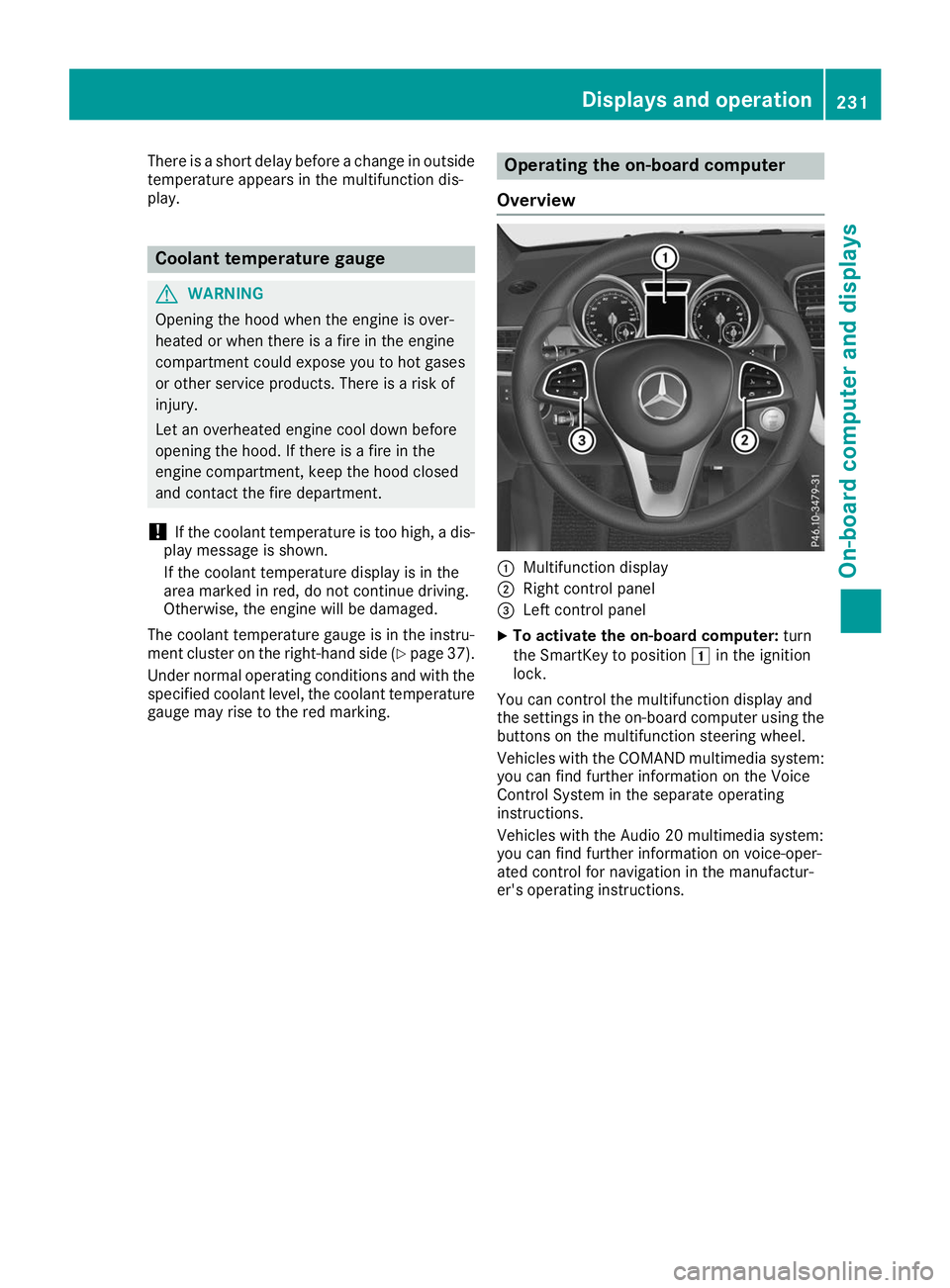
Overview 0043
Multifunction display
0044 Right control panel
0087 Left control panel
X To activate the on-board computer: turn
the SmartKey to position 0047in the ignition
lock.
You can control the multifunction display and
the settings in the on-board computer using the buttons on the multifunction steering wheel.
Vehicles with the COMAND multimedia system: you can find further information on the Voice
Control System in the separate operating
instructions.
Vehicles with the Audio 20 multimedia system:
you can find further information on voice-oper-
ated control for navigation in the manufactur-
er's operating instructions. Displays and operation
231On-board computer and displays Z
Page 242 of 398
Settings menu
Introduction Depending on the equipment installed in the
vehicle, In the
Sett. Sett.menu you have the follow-
ing options:
R Changing the instrument cluster settings
(Y page 240)
R Changing the light settings (Y page 240)
R Changing the vehicle settings (Y page 241)
R Changing the convenience settings
(Y page 241)
R Restoring the factory settings (Y page 242)
Instrument cluster submenu Selecting the distance unit
The Display Unit Speedometer / Odome‐ Display Unit Speedometer / Odome‐
ter:
ter: function allows you to choose whether
certain displays appear in kilometers or miles in
the multifunction display.
X Press the 0059or0065 button on the steering
wheel to select the Sett.
Sett. menu.
X Press the 0064or0063 button to select the
Instrument Cluster
Instrument Cluster submenu.
X Press 0076to confirm.
X Press the 0064or0063 button to select the
Display Unit Speedometer / Odometer
Display Unit Speedometer / Odometer
function.
You will see the selected setting: km kmormiles
miles.
X Press the 0076button to save the setting.
The selected unit of measurement for distance
applies to:
R Digital speedometer in the Trip
Trip menu
R Odometer and the trip odometer
R Trip computer
R Current consumption and the range
R Navigation instructions in the Navi
Navimenu
R Cruise control
R Active Distance Assist DISTRONIC
R ASSYST PLUS service interval display
Selecting permanent display
The Permanent Display:
Permanent Display: function allows you
to choose whether the multifunction display
always shows the outside temperature or the
speed. The speed display is inverse to the speedome-
ter.
X Press the 0059or0065 button on the steering
wheel to select the Sett. Sett.menu.
X Press the 0064or0063 button to select the
Instrument Cluster
Instrument Cluster submenu.
X Confirm by pressing 0076on the steering
wheel.
X Press the 0064or0063 button to select the
Permanent Display:
Permanent Display: function.
The current setting, Outside Temperature
Outside Temperature,
Speedometer [km/h]
Speedometer [km/h] orSpeedometer
Speedometer
[mph]
[mph] appears.
X To change the setting: press0076again.
Light submenu Setting the daytime running lamps
This function is not available in Canada.
X Press the 0059or0065 button on the steering
wheel to select the Sett.
Sett.menu.
X Press the 0064or0063 button to select the
Light
Light submenu.
X Press 0076to confirm.
X Press 0064or0063 to select the Daytime
Daytime
Running Lights
Running Lights function.
If the Daytime
Daytime Running
RunningLights
Lightsfunction has
been switched on, the cone of light and the
0086 symbol in the multifunction display are
shown in orange.
X Press the 0076button to save the setting.
Further information on daytime running lamps
(Y page 115).
Switching the Intelligent Light System
on/off
X Press the 0059or0065 button on the steering
wheel to select the Sett.
Sett. menu.
X Press the 0064or0063 button to select the
Light Light submenu.
X Press 0076to confirm.
X Press the 0064or0063 button to select the
Intell. Light System
Intell. Light System function.
If the Intell. Light System
Intell. Light System function has
been switched on, the cone of light and the
0058 symbol in the multifunction display are
shown in orange.
X Press the 0076button to save the setting.
When you activate Intell. Light System Intell. Light System,
you activate the following functions: 240
Menus and submenusOn-board computer and displays
Page 265 of 398
Display messages
Possible causes/consequences and
0050
0050Solutions ACTIVE
ACTIVE
CURVE
CURVESYSTEM
SYSTEM
Malfunction See
Malfunction See
Operator's Manual Operator's Manual The ACTIVE CURVE SYSTEM is faulty. The vehicle's handling charac-
teristics are severely impaired. A warning tone also sounds.
G WARNING
There is a risk of an accident.
X Drive on carefully.
X Adjust your driving style to the altered handling characteristics.
X Avoid sudden acceleration around tight corners and fast steering
movements.
X Do not drive at speeds above 50 mph (80 km/h).
X Visit a qualified specialist workshop immediately. 003B
Different. Lock Different. Lock
Sys. Malfunction Sys. Malfunction The differential lock is faulty.
X Do not drive at speeds above 50 mph (80 km/h).
X Visit a qualified specialist workshop. 003B
Different. Locking Different. Locking
Sys. Cooling Down Sys. Cooling Down
Please Wait Please Wait The differential lock is too hot and has been disengaged.
X Drive on carefully.
X Allow the differential lock to cool down.
The differential lock re-engages as soon as it has cooled down. LOW RANGE Stop LOW RANGE Stop
Apply Parking Brake Apply Parking Brake A gearshift process has been canceled. LOW RANGE is in the neutral
position. There is no connection between the engine and the drive
wheels.
X Pull over and stop the vehicle safely as soon as possible, paying
attention to road and traffic conditions.
X Apply the electric parking brake. Do not continue driving under any
circumstances.
X Repeat the gearshift process. LOW RANGE Malfunc‐
LOW RANGE Malfunc‐
tion tion
To
ToPark,
Park, Apply
Apply
Brake
Brake LOW RANGE is malfunctioning.
X Do not drive at speeds above 31 mph (50 km/h).
X When parking, secure the vehicle against rolling away (Y page 158).
X Visit a qualified specialist workshop. LOW RANGE Max.
LOW RANGE Max.
Speed 25 mph Speed 25 mph You have exceeded the maximum speed for the gearshift process.
X Drive more slowly.
The gear change is made. LOW RANGE Max. LOW RANGE Max.
Speed 31 mph Speed 31 mph You have exceeded the maximum speed for the gearshift process.
X Drive more slowly.
The gear change is made. LOW RANGE Shift to LOW RANGE Shift to
Position N Briefly Position N Briefly You have reduced the vehicle speed, but the automatic transmission
is not in position 005C.
X Briefly shift the automatic transmission to 005C. Display
messages
263On-board computer and displays Z
Page 270 of 398
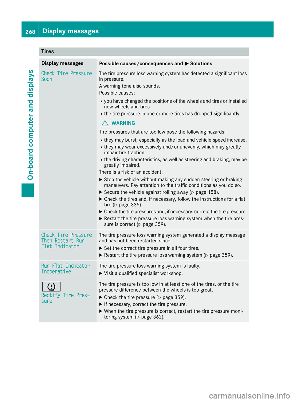
Tires
Display messages
Possible causes/consequences and
0050
0050Solutions Check
Check
Tire
TirePressure
Pressure
Soon
Soon The tire pressure loss warning system has detected a significant loss
in pressure.
A warning tone also sounds.
Possible causes:
R you have changed the positions of the wheels and tires or installed
new wheels and tires
R the tire pressure in one or more tires has dropped significantly
G WARNING
Tire pressures that are too low pose the following hazards: R they may burst, especially as the load and vehicle speed increase.
R they may wear excessively and/or unevenly, which may greatly
impair tire traction.
R the driving characteristics, as well as steering and braking, may be
greatly impaired.
There is a risk of an accident.
X Stop the vehicle without making any sudden steering or braking
maneuvers. Pay attention to the traffic conditions as you do so.
X Secure the vehicle against rolling away (Y page 158).
X Check the tires and, if necessary, follow the instructions for a flat
tire (Y page 335).
X Check the tire pressures and, if necessary, correct the tire pressure.
X Restart the tire pressure loss warning system when the tire pres-
sure is correct (Y page 359). Check Check
Tire
TirePressure
Pressure
Then Restart Run
Then Restart Run
Flat Indicator Flat Indicator The tire pressure loss warning system generated a display message
and has not been restarted since.
X Set the correct tire pressure in all four tires.
X Restart the tire pressure loss warning system (Y page 359).Run Flat Indicator Run Flat Indicator
Inoperative Inoperative The tire pressure loss warning system is faulty.
X Visit a qualified specialist workshop. 0077
Rectify Tire Pres‐ Rectify Tire Pres‐
sure sure The tire pressure is too low in at least one of the tires, or the tire
pressure difference between the wheels is too great.
X Check the tire pressure (Y page 359).
X If necessary, correct the tire pressure.
X When the tire pressure is correct, restart the tire pressure moni-
toring system (Y page 362).268
Display
messagesOn-board computer and displays
Page 297 of 398
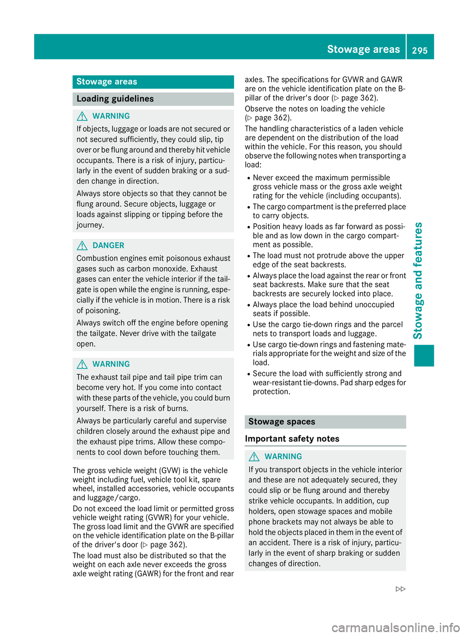
Stowage areas
Loading guidelines
G
WARNING
If objects, luggage or loads are not secured or not secured sufficiently, they could slip, tip
over or be flung around and thereby hit vehicle
occupants. There is a risk of injury, particu-
larly in the event of sudden braking or a sud-
den change in direction.
Always store objects so that they cannot be
flung around. Secure objects, luggage or
loads against slipping or tipping before the
journey. G
DANGER
Combustion engines emit poisonous exhaust
gases such as carbon monoxide. Exhaust
gases can enter the vehicle interior if the tail- gate is open while the engine is running, espe-cially if the vehicle is in motion. There is a risk of poisoning.
Always switch off the engine before opening
the tailgate. Never drive with the tailgate
open. G
WARNING
The exhaust tail pipe and tail pipe trim can
become very hot. If you come into contact
with these parts of the vehicle, you could burn
yourself. There is a risk of burns.
Always be particularly careful and supervise
children closely around the exhaust pipe and
the exhaust pipe trims. Allow these compo-
nents to cool down before touching them.
The gross vehicle weight (GVW) is the vehicle
weight including fuel, vehicle tool kit, spare
wheel, installed accessories, vehicle occupants and luggage/cargo.
Do not exceed the load limit or permitted grossvehicle weight rating (GVWR) for your vehicle.
The gross load limit and the GVWR are specified
on the vehicle identification plate on the B-pillar
of the driver's door (Y page 362).
The load must also be distributed so that the
weight on each axle never exceeds the gross
axle weight rating (GAWR) for the front and rear axles. The specifications for GVWR and GAWR
are on the vehicle identification plate on the B-
pillar of the driver's door (Y
page 362).
Observe the notes on loading the vehicle
(Y page 362).
The handling characteristics of a laden vehicle
are dependent on the distribution of the load
within the vehicle. For this reason, you should
observe the following notes when transporting a
load:
R Never exceed the maximum permissible
gross vehicle mass or the gross axle weight
rating for the vehicle (including occupants).
R The cargo compartment is the preferred place
to carry objects.
R Position heavy loads as far forward as possi-
ble and as low down in the cargo compart-
ment as possible.
R The load must not protrude above the upper
edge of the seat backrests.
R Always place the load against the rear or front
seat backrests. Make sure that the seat
backrests are securely locked into place.
R Always place the load behind unoccupied
seats if possible.
R Use the cargo tie-down rings and the parcel
nets to transport loads and luggage.
R Use cargo tie-down rings and fastening mate-
rials appropriate for the weight and size of the load.
R Secure the load with sufficiently strong and
wear-resistant tie-downs. Pad sharp edges for
protection. Stowage spaces
Important safety notes G
WARNING
If you transport objects in the vehicle interior and these are not adequately secured, they
could slip or be flung around and thereby
strike vehicle occupants. In addition, cup
holders, open stowage spaces and mobile
phone brackets may not always be able to
hold the objects placed in them in the event of an accident. There is a risk of injury, particu-
larly in the event of sharp braking or sudden
changes of direction. Stowage areas
295Stowage and features
Z
Page 314 of 398
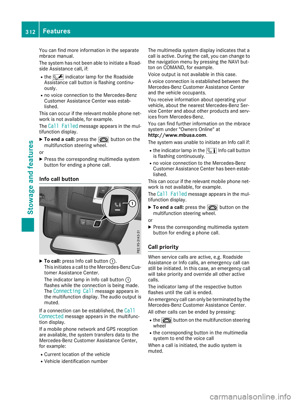
You can find more information in the separate
mbrace manual.
The system has not been able to initiate a Road-
side Assistance call, if:
R the 0052 indicator lamp for the Roadside
Assistance call button is flashing continu-
ously.
R no voice connection to the Mercedes-Benz
Customer Assistance Center was estab-
lished.
This can occur if the relevant mobile phone net-
work is not available, for example.
The Call Failed Call Failed message appears in the mul-
tifunction display.
X To end a call: press the0076button on the
multifunction steering wheel.
or X Press the corresponding multimedia system
button for ending a phone call.
Info call button X
To call: press Info call button 0043.
This initiates a call to the Mercedes-Benz Cus-
tomer Assistance Center.
The indicator lamp in Info call button 0043
flashes while the connection is being made.
The Connecting Call
Connecting Call message appears in
the multifunction display. The audio output is muted.
If a connection can be established, the Call Call
Connected
Connected message appears in the multifunc-
tion display.
If a mobile phone network and GPS reception
are available, the system transfers data to the
Mercedes-Benz Customer Assistance Center,
for example:
R Current location of the vehicle
R Vehicle identification number The multimedia system display indicates that a
call is active. During the call, you can change to
the navigation menu by pressing the NAVI but-
ton on COMAND, for example.
Voice output is not available in this case.
A voice connection is established between the
Mercedes-Benz Customer Assistance Center
and the vehicle occupants.
You receive information about operating your
vehicle, about the nearest Mercedes-Benz Ser-
vice Center and about other products and serv- ices from Mercedes-Benz.
You can find further information on the mbrace
system under "Owners Online" at
http://www.mbusa.com.
The system was unable to initiate an Info call if:
R the indicator lamp in the 00D9Info call button
is flashing continuously.
R no voice connection to the Mercedes-Benz
Customer Assistance Center has been estab-
lished.
This can occur if the relevant mobile phone net-
work is not available, for example.
The Call Failed
Call Failed message appears in the mul-
tifunction display.
X To end a call: press the0076button on the
multifunction steering wheel.
or X Press the corresponding multimedia system
button for ending a phone call.
Call priority When service calls are active, e.g. Roadside
Assistance or Info calls, an emergency call can
still be initiated. In this case, an emergency call
will take priority and override all other active
calls.
The indicator lamp of the respective button
flashes until the call is ended.
An emergency call can only be terminated by the
Mercedes-Benz Customer Assistance Center.
All other calls can be ended by pressing:
R the 0076 button on the multifunction steering
wheel
R the corresponding button in the multimedia
system to end the voice call
When a call is initiated, the audio system is
muted. 312
FeaturesStowage and features
Page 327 of 398
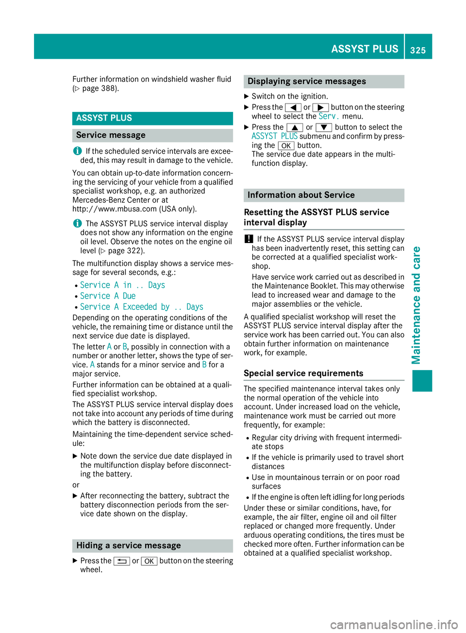
Further information on windshield washer fluid
(Y page 388). ASSYST PLUS
Service message
i If the scheduled service intervals are excee-
ded, this may result in damage to the vehicle.
You can obtain up-to-date information concern-
ing the servicing of your vehicle from a qualified specialist workshop, e.g. an authorized
Mercedes-Benz Center or at
http://www.mbusa.com (USA only).
i The ASSYST PLUS service interval display
does not show any information on the engine
oil level. Observe the notes on the engine oil
level (Y page 322).
The multifunction display shows a service mes-
sage for several seconds, e.g.:
R Service A in .. Days Service A in .. Days
R Service A Due
Service A Due
R Service A Exceeded by .. Days
Service A Exceeded by .. Days
Depending on the operating conditions of the
vehicle, the remaining time or distance until the next service due date is displayed.
The letter A
A or B B, possibly in connection with a
number or another letter, shows the type of ser-
vice. A
A stands for a minor service and B
Bfor a
major service.
Further information can be obtained at a quali-
fied specialist workshop.
The ASSYST PLUS service interval display does
not take into account any periods of time during
which the battery is disconnected.
Maintaining the time-dependent service sched-
ule:
X Note down the service due date displayed in
the multifunction display before disconnect-
ing the battery.
or
X After reconnecting the battery, subtract the
battery disconnection periods from the ser-
vice date shown on the display. Hiding a service message
X Press the 0038or0076 button on the steering
wheel. Displaying service messages
X Switch on the ignition.
X Press the 0059or0065 button on the steering
wheel to select the Serv. Serv.menu.
X Press the 0063or0064 button to select the
ASSYST
ASSYST PLUS
PLUSsubmenu and confirm by press-
ing the 0076button.
The service due date appears in the multi-
function display. Information about Service
Resetting the ASSYST PLUS service
interval display !
If the ASSYST PLUS service interval display
has been inadvertently reset, this setting can
be corrected at a qualified specialist work-
shop.
Have service work carried out as described in the Maintenance Booklet. This may otherwise
lead to increased wear and damage to the
major assemblies or the vehicle.
A qualified specialist workshop will reset the
ASSYST PLUS service interval display after the
service work has been carried out. You can also obtain further information on maintenance
work, for example.
Special service requirements The specified maintenance interval takes only
the normal operation of the vehicle into
account. Under increased load on the vehicle,
maintenance work must be carried out more
frequently, for example:
R Regular city driving with frequent intermedi-
ate stops
R If the vehicle is primarily used to travel short
distances
R Use in mountainous terrain or on poor road
surfaces
R If the engine is often left idling for long periods
Under these or similar conditions, have, for
example, the air filter, engine oil and oil filter
replaced or changed more frequently. Under
arduous operating conditions, the tires must be checked more often. Further information can be
obtained at a qualified specialist workshop. ASSYST PLUS
325Maintenance and care Z