2019 MERCEDES-BENZ GLS weight
[x] Cancel search: weightPage 54 of 398
In the following situation, the side impact air bag
and the Emergency Tensioning Device are deac-
tivated:
R OCS has not categorized the person on the
front-passenger seat as an adult or a person
of corresponding stature and
R the seat belt buckle tongue of the seat belt is
not inserted into the front-passenger seat belt buckle
Requirements To be classified correctly, the front passenger
must sit:
R with the seat belt fastened correctly
R in an almost upright position with their back
against the seat backrest
R with their feet resting on the floor, if possible
If the front passenger does not observe these
conditions, OCS may produce a false classifica-
tion, e.g. because the front passenger:
R transfers their weight by supporting them-
selves on a vehicle armrest
R sits in such a way that their weight is raised
from the seat cushion
If it is absolutely necessary to install a child
restraint system on the front-passenger seat, be
sure to observe the correct positioning of the
child restraint system. Never place objects
under or behind the child restraint system, e.g. a
cushion. The entire base of the child restraint
system must always rest on the seat cushion of the front-passenger seat. The backrest of the
forward-facing child restraint system must lie as
flat as possible against the backrest of the front-
passenger seat.
The child restraint system must not touch the
roof or be subjected to a load by the head
restraint. Adjust the angle of the seat backrest
and the head restraint position accordingly.
Only then can OCS be guaranteed to function
correctly. Always observe the child restraint sys-
tem manufacturer's installation and operating
instructions. Occupant Classification System opera-
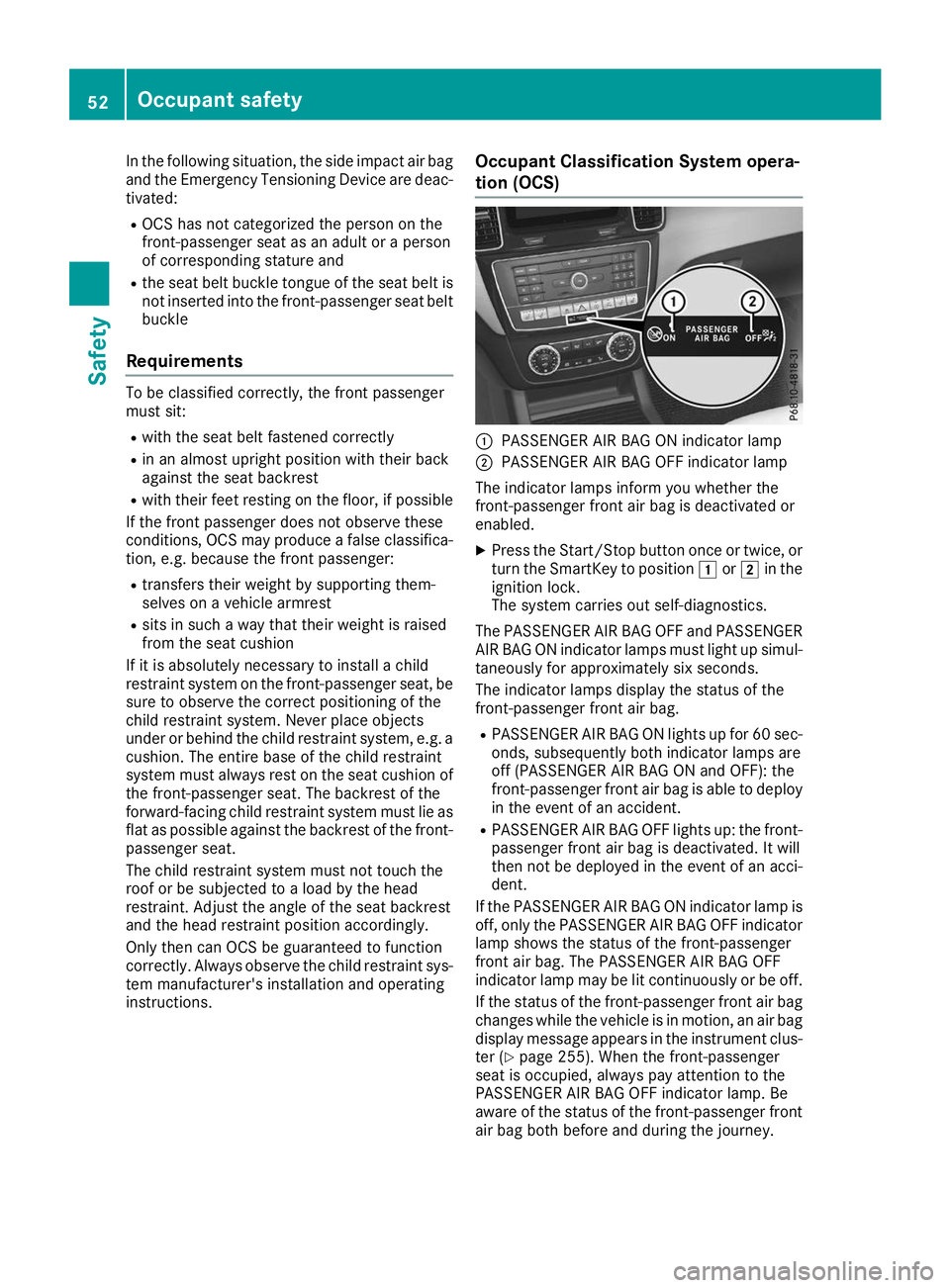
tion (OCS) 0043
PASSENGER AIR BAG ON indicator lamp
0044 PASSENGER AIR BAG OFF indicator lamp
The indicator lamps inform you whether the
front-passenger front air bag is deactivated or
enabled.
X Press the Start/Stop button once or twice, or
turn the SmartKey to position 0047or0048 in the
ignition lock.
The system carries out self-diagnostics.
The PASSENGER AIR BAG OFF and PASSENGER
AIR BAG ON indicator lamps must light up simul- taneously for approximately six seconds.
The indicator lamps display the status of the
front-passenger front air bag.
R PASSENGER AIR BAG ON lights up for 60 sec-
onds, subsequently both indicator lamps are
off (PASSENGER AIR BAG ON and OFF): the
front-passenger front air bag is able to deploy in the event of an accident.
R PASSENGER AIR BAG OFF lights up: the front-
passenger front air bag is deactivated. It will
then not be deployed in the event of an acci-
dent.
If the PASSENGER AIR BAG ON indicator lamp is
off, only the PASSENGER AIR BAG OFF indicator lamp shows the status of the front-passenger
front air bag. The PASSENGER AIR BAG OFF
indicator lamp may be lit continuously or be off.
If the status of the front-passenger front air bag
changes while the vehicle is in motion, an air bag display message appears in the instrument clus-
ter (Y page 255). When the front-passenger
seat is occupied, always pay attention to the
PASSENGER AIR BAG OFF indicator lamp. Be
aware of the status of the front-passenger front
air bag both before and during the journey. 52
Occupant safetySafety
Page 58 of 398
Problem
Possible causes/consequences and
0050
0050Solutions The PASSENGER AIR
BAG OFF indicator lamp
lights up and remains lit,
even though the front-
passenger seat is occu-
pied by an adult or a per-
son of a stature corre-
sponding to that of an
adult. The classification of the person on the front-passenger seat is incor-
rect.
X Make sure the conditions for a correct classification of the person
on the front-passenger seat are met (Y page 52).
X If the PASSENGER AIR BAG OFF indicator lamp remains lit, the front-
passenger seat may not be used.
X Have OCS checked as soon as possible at an authorized Mercedes-
Benz Center. The PASSENGER AIR
BAG OFF indicator lamp
does not light up and/or
does not stay on.
The front-passenger seatis:
R unoccupied
R occupied by the
weight of a child up to
twelve months old in achild restraint system OCS is malfunctioning.
X Make sure there is nothing between the seat cushion and the child
seat.
X Make sure that the entire base of the child restraint system rests on
the seat cushion of the front-passenger seat. The backrest of the
forward-facing child restraint system must lie as flat as possible
against the backrest of the front passenger seat. If necessary,
adjust the position of the front-passenger seat.
X When installing the child restraint system, make sure that the seat
belt is tight. Do not pull the seat belt tight using the front-passenger
seat adjustment. This could result in the seat belt and the child
restraint system being pulled too tightly.
X Check for correct installation of the child restraint system.
Make sure that the head restraint does not apply a load to the child restraint system. If necessary, adjust the head restraint accord-
ingly.
X Make sure that no objects are applying additional weight onto the
seat.
X If the PASSENGER AIR BAG OFF indicator lamp remains off and/or
the PASSENGER AIR BAG ON indicator lamp lights up, do not install a child restraint system on the front-passenger seat. It is recom-
mended that you install the child restraint system on a suitable rear
seat.
X Have OCS checked as soon as possible at an authorized Mercedes-
Benz Center. Deployment of Emergency Tensioning
Devices and air bags
Important safety notes G
WARNING
The air bag parts are hot after an air bag has
been deployed. There is a risk of injury.
Do not touch the air bag parts. Have a
deployed air bag replaced at a qualified spe-
cialist workshop as soon as possible. G
WARNING
A deployed air bag no longer offers any pro-
tection and cannot provide the intended pro-
tection in an accident. There is an increased
risk of injury.
Have the vehicle towed to a qualified special- ist workshop in order to have a deployed air
bag replaced.
It is important for your safety and that of your
passenger to have deployed air bags replaced
and to have any malfunctioning air bags 56
Occupant safetySafety
Page 62 of 398
a child restraint system on a rear seat. Children
are generally better protected there.
If a child younger than twelve years old and
under 5 ft (1.50 m) in height is traveling in the
vehicle:
R always secure the child in a child restraint
system suitable for Mercedes-Benz vehicles.
The child restraint system must be appropri-
ate to the age, weight and size of the child.
R be sure to observe the instructions and safety
notes in this section in addition to the child
restraint system manufacturer's installation
instructions.
R always observe the instructions and safety
notes on the "Occupant classification system (OCS)". (Y page 51) G
WARNING
If you leave children unsupervised in the vehi- cle, they could set it in motion by, for example:
R release the parking brake.
R shift the automatic transmission out of the
parking position P.
R start the engine.
In addition, they may operate vehicle equip-
ment and become trapped. There is a risk of
an accident and injury.
When leaving the vehicle, always take the
SmartKey with you and lock the vehicle. Never
leave children unsupervised in the vehicle. G
WARNING
If persons, particularly children are subjected to prolonged exposure to extreme heat or
cold, there is a risk of injury, possibly even
fatal. Never leave children unattended in the
vehicle. G
WARNING
If the child restraint system is subjected to
direct sunlight, parts may get very hot. Chil-
dren may burn themselves on these parts,
particularly on the metal parts of the child
restraint system. There is a risk of injury.
If you leave the vehicle, taking the child with
you, always ensure that the child restraint
system is not exposed to direct sunlight. Pro- tect it with a blanket, for example. If the child
restraint system has been exposed to direct
sunlight, let it cool down before securing the
child in it. Never leave children unattended in the vehicle.
Always ensure that all vehicle occupants have
their seat belts fastened correctly and are sitting properly. Particular attention must be paid to
children.
Observe the safety notes on the seat belt
(Y page 46) and the notes on correct use of seat
belts (Y page 47).
A booster seat may be necessary to achieve
proper seat belt positioning for children over
40 lbs (18 kg) until they reach a height where a
three-point seat belt can be properly fastened
without a booster seat. Special seatbelt retractor
G
WARNING
If the seat belt is released while driving, the
child restraint system will no longer be
secured properly. The special seat belt retrac- tor is disabled and the inertia real draws in a
portion of the seat belt. The seat belt cannot
be immediately refastened. There is an
increased risk of injury, possibly even fatal.
Stop the vehicle immediately, paying atten-
tion to road and traffic conditions. Reactivate
the special seat belt retractor and secure the
child restraint system properly.
All seat belts in the vehicle, except the driver's
seat belt, are equipped with a special seat belt
retractor. When activated, the special seat belt
retractor ensures that the seat belt cannot
slacken once the child seat is secured.
Installing a child restraint system:
X Make sure you observe the child restraint
system manufacturer's installation instruc-
tions.
X Pull the seat belt smoothly from the belt out-
let.
X Engage seat belt tongue in belt buckle. 60
Children in the vehicleSafety
Page 64 of 398
All child restraint systems must meet the fol-
lowing standards:
R U.S. Federal Motor Vehicle Safety Standards
213 and 225
R Canadian Motor Vehicle Safety Standards
213 and 210.2
Confirmation that the child restraint system cor- responds to the standards can be found on an
instruction label on the child restraint system.
This confirmation can also be found in the instal-
lation instructions that are included with the
child restraint system.
Observe the warning labels in the vehicle inte-
rior and on the child restraint system. LATCH-type (ISOFIX) child seat secur-
ing system G
WARNING
For LATCH-type (ISOFIX) child restraint sys-
tems in which the child is secured using the
safety belt integrated in the child restraint
system, the maximum permissible weight of
the child and child restraint system together
is 73 lbs (33 kg).
If the child and the child restraint system
together weigh more than 73 lbs (33 kg), the
LATCH-type (ISOFIX) child restraint system
with integrated safety belt no longer offers
sufficient protection. The LATCH-type (ISO-
FIX) child seat securing system may be over-
loaded, and the child may not be restrained in
an accident, for example. This poses an
increased risk of injury or even fatal injury.
If the child and the child restraint system
together weigh more than 73 lb s(33 kg), use
only a LATCH-type (ISOFIX) child restraint sys-
tem in which the child is also secured with the vehicle seat belt. Also secure the child
restraint system with the Top Tether belt, if
available.
Regularly check that the permissible gross
weight of the child together with the child
restraint system is still maintained.
Always comply with the manufacturer's instal-
lation and operating instructions for the child
restraint system used. Before every trip, make sure that the LATCH-
type (ISOFIX) child restraint system is engaged
correctly in both LATCH-type (ISOFIX) securing
rings
To ensure that the LATCH-type (ISOFIX) child
restraint system can perform its protective func-
tion as intended, the backrest of the respective outer seat in the second row must be in the
upright position.
! When installing the child restraint system,
make sure that the seat belt for the middle
seat does not get trapped. The seat belt could
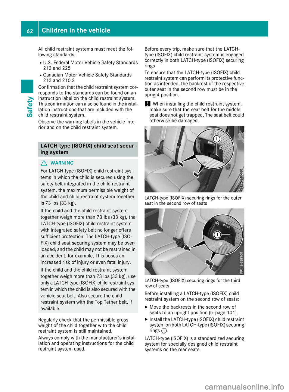
otherwise be damaged. LATCH-type (ISOFIX) securing rings for the outer
seat in the second row of seats
LATCH-type (ISOFIX) securing rings for the third
row of seats
Before installing a LATCH-type (ISOFIX) child
restraint system on the second row of seats:
X Move the backrests in the second row of
seats to an upright position (Y page 101).
X Install the LATCH-type (ISOFIX) child restraint
system on both LATCH-type (ISOFIX) securing
rings 0043.
LATCH-type (ISOFIX) is a standardized securing system for specially designed child restraint
systems on the rear seats. 62
Children in the vehicleSafety
Page 223 of 398
006D
Level control
006E Compass with angle scale
Activating the driving dynamics display X
Switch on COMAND (see the Digital Opera-
tor's Manual).
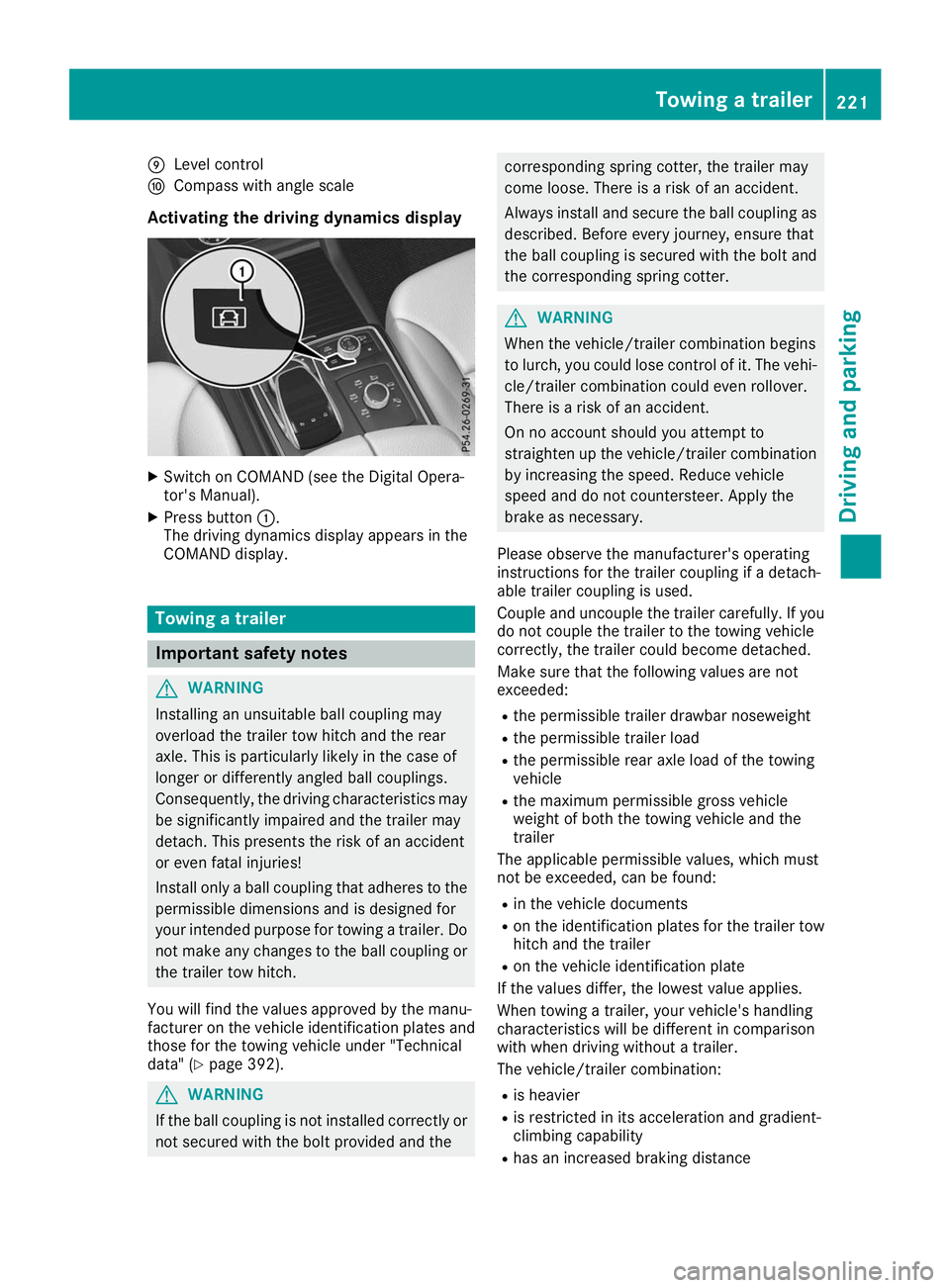
X Press button 0043.
The driving dynamics display appears in the
COMAND display. Towing a trailer
Important safety notes
G
WARNING
Installing an unsuitable ball coupling may
overload the trailer tow hitch and the rear
axle. This is particularly likely in the case of
longer or differently angled ball couplings.
Consequently, the driving characteristics may
be significantly impaired and the trailer may
detach. This presents the risk of an accident
or even fatal injuries!
Install only a ball coupling that adheres to the permissible dimensions and is designed for
your intended purpose for towing a trailer. Do
not make any changes to the ball coupling or the trailer tow hitch.
You will find the values approved by the manu-
facturer on the vehicle identification plates and
those for the towing vehicle under "Technical
data" (Y page 392). G
WARNING
If the ball coupling is not installed correctly or not secured with the bolt provided and the corresponding spring cotter, the trailer may
come loose. There is a risk of an accident.
Always install and secure the ball coupling as
described. Before every journey, ensure that
the ball coupling is secured with the bolt and
the corresponding spring cotter. G
WARNING
When the vehicle/trailer combination begins
to lurch, you could lose control of it. The vehi- cle/trailer combination could even rollover.
There is a risk of an accident.
On no account should you attempt to
straighten up the vehicle/trailer combination
by increasing the speed. Reduce vehicle
speed and do not countersteer. Apply the
brake as necessary.
Please observe the manufacturer's operating
instructions for the trailer coupling if a detach-
able trailer coupling is used.
Couple and uncouple the trailer carefully. If you do not couple the trailer to the towing vehicle
correctly, the trailer could become detached.
Make sure that the following values are not
exceeded:
R the permissible trailer drawbar noseweight
R the permissible trailer load
R the permissible rear axle load of the towing
vehicle
R the maximum permissible gross vehicle
weight of both the towing vehicle and the
trailer
The applicable permissible values, which must
not be exceeded, can be found:
R in the vehicle documents
R on the identification plates for the trailer tow
hitch and the trailer
R on the vehicle identification plate
If the values differ, the lowest value applies.
When towing a trailer, your vehicle's handling
characteristics will be different in comparison
with when driving without a trailer.
The vehicle/trailer combination:
R is heavier
R is restricted in its acceleration and gradient-
climbing capability
R has an increased braking distance Towing a trailer
221Driving and parking Z
Page 228 of 398
Decoupling a trailer
G
WARNING
If you uncouple a trailer with the overrun
brake engaged, you could trap your hand
between the vehicle and the trailer drawbar.
There is a risk of injury.
Do not uncouple a trailer if the overrun brake is engaged. G
WARNING
Vehicles with level control:
The vehicle is lowered as soon as you discon-
nect the trailer cable. This could result in your limbs or those of other people that are
between the vehicle body and tires or under-
neath the vehicle being trapped. There is a
risk of injury.
Make sure that nobody is in the immediate
vicinity of the wheel housings or under the
vehicle when you disconnect the trailer cable.
! Do not disconnect a trailer with an engaged
overrun brake. Otherwise, your vehicle could
be damaged by the rebounding of the overrun
brake.
X Shift the transmission to position 005D.
X Apply the vehicle's electric parking brake.
X Start the engine.
X Close the doors and tailgate.
X Apply the trailer's parking brake.
X Detach the trailer cable and decouple the
trailer.
X Switch off the engine. Permissible trailer loads and drawbar
loads
Weight specifications Maximum allowable gross mass
The gross vehicle weight of the trailer is calcu-
lated by adding the weight of the trailer to the
weight of the load and equipment on the trailer.
You will find installing dimensions and loads
under "Technical data" (Y page 392).Permissible noseweight
You will find installing dimensions and loads
under "Technical data" (Y page 392).
Loading a trailer R
When loading the trailer, make sure that nei-
ther the permissible gross weight of the trailer
nor the gross vehicle weight are exceeded.
The permissible gross vehicle weight is indi-
cated on the identification plate located on
the B-pillar on the driver's side of the vehicle.
You can find the maximum permissible values
on the type plates of your vehicle and the
trailer. When calculating how much weight
the vehicle and trailer may carry, pay atten-
tion to the respective lowest values.
R The trailer drawbar load on the ball coupling
must be added to the rear axle load to avoid
exceeding the permissible gross axle weight.
The permissible gross vehicle weight is indi-
cated on the identification plate located on
the B-pillar on the driver's side of the vehicle.
i Mercedes-Benz recommends a trailer load
where the trailer drawbar noseweight
accounts for 8 % to 15 % of the trailer's per-
missible gross weight.
i The weight of additional accessories, pas-
sengers, and cargo reduces the permissible
trailer load and drawbar load for your vehicle.
Checking the vehicle and trailer weight R
To check that the weights of the towing vehi-
cle and the trailer comply with the maximum
permissible values, have the vehicle/trailer
combination (including the driver, passen-
gers, and cargo with a fully laden trailer)
weighed on a calibrated weighbridge.
R Check the gross axle weight rating of the front
and rear axles, the gross weight of the trailer
and the trailer drawbar noseweight. Removing the ball coupling
X Remove the spring cotter.
X Remove the bolt from the ball coupling
recess.
X Remove the ball coupling from the ball cou-
pling recess. 226
Towing a trailerDriving and pa
rking
Page 229 of 398
X
Clean the ball coupling if it is dirty.
X Stow the ball coupling so that it cannot be
thrown around.
Observe the loading guidelines (Y page 295)
and the safety notes regarding stowage spaces
(Y page 295).
Information on cleaning and care of the trailer
tow hitch (Y page 331). Trailer power supply
! Accessories with a maximum power con-
sumption of 180 W can be connected to the
permanent power supply.
You must not charge a trailer battery using the
power supply.
The trailer socket of your vehicle is equipped at
the factory with a permanent power supply.
The permanent power supply is supplied via
trailer socket pin 4.
The trailer's permanent power supply is
switched off in the event of low vehicle supply
voltage and after six hours at the latest.
A qualified specialist workshop can provide
more information about installing the trailer
electrics. Bicycle rack
General notes
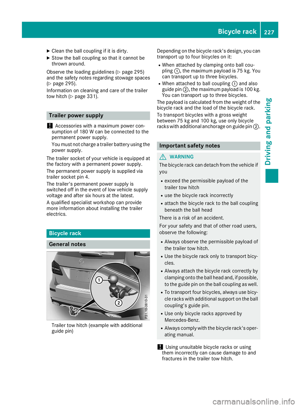
Trailer tow hitch (example with additional
guide pin) Depending on the bicycle rack's design, you can
transport up to four bicycles on it:
R When attached by clamping onto ball cou-
pling 0043, the maximum payload is 75 kg. You
can transport up to three bicycles.
R When attached to ball coupling 0043and also
guide pin 0044, the maximum payload is 100 kg.
You can transport up to three bicycles.
The payload is calculated from the weight of the
bicycle rack and the load of the bicycle rack.
To transport bicycles with a gross weight
between 75 kg and 100 kg, use only bicycle
racks with additional anchorage on guide pin 0044. Important safety notes
G
WARNING
The bicycle rack can detach from the vehicle if
you
R exceed the permissible payload of the
trailer tow hitch
R use the bicycle rack incorrectly
R attach the bicycle rack to the ball coupling
beneath the ball head
There is a risk of an accident.
For your safety and that of other road users,
observe the following:
R Always observe the permissible payload of
the trailer tow hitch.
R Use the bicycle rack only to transport bicy-
cles.
R Always attach the bicycle rack correctly by
clamping onto the ball head and, if possible, to the guide pin on the ball coupling as well.
R To transport four bicycles, always use bicy-
cle racks with additional support on the ball
coupling's guide pin.
R Use only bicycle racks approved by
Mercedes-Benz.
R Always comply with the bicycle rack's oper-
ating manual.
! Using unsuitable bicycle racks or using
them incorrectly can cause damage to and
fractures in the trailer tow hitch. Bicycle rack
227Driving and parking Z
Page 231 of 398
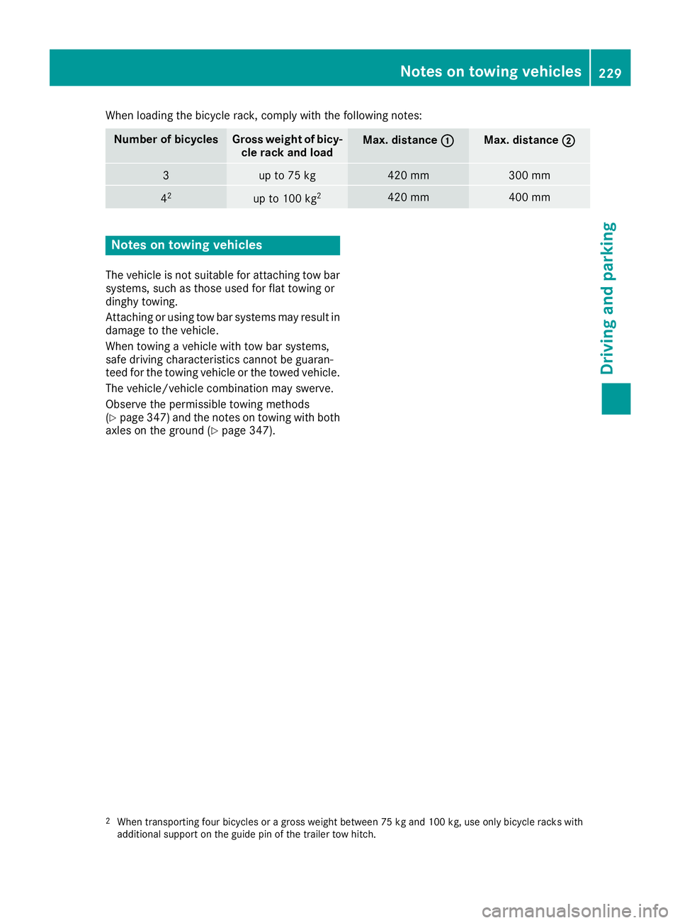
When loading the bicycle rack, comply with the following notes:
Number of bicycles Gross weight of bicy-
cle rack and load Max. distance
0043
0043 Max. distance
0044
0044 3 up to 75 kg 420 mm 300 mm
4
2 up to 100 kg
2 420 mm 400 mm
Notes on towing vehicles
The vehicle is not suitable for attaching tow bar
systems, such as those used for flat towing or
dinghy towing.
Attaching or using tow bar systems may result in
damage to the vehicle.
When towing a vehicle with tow bar systems,
safe driving characteristics cannot be guaran-
teed for the towing vehicle or the towed vehicle.
The vehicle/vehicle combination may swerve.
Observe the permissible towing methods
(Y page 347) and the notes on towing with both
axles on the ground (Y page 347).
2 When transporting four bicycles or a gross weight between 75 kg and 100 kg, use only bicycle racks with
additional support on the guide pin of the trailer tow hitch. Notes on towing vehicles
229Driving and parking Z