Page 374 of 398

be required earlier. Do not change the direction
of wheel rotation.
Clean the contact surfaces of the wheel and the
brake disc thoroughly every time a wheel is rota- ted. Check the tire pressure and, if necessary,
restart the tire pressure loss warning system or
the tire pressure monitor (Y page 358).Direction of rotation
Tires with a specified direction of rotation have
additional benefits, e.g. if there is a risk of hydro-
planing. These advantages can only be gained if the tires are installed corresponding to the
direction of rotation.
An arrow on the sidewall of the tire indicates itscorrect direction of rotation. Storing wheels
Store wheels that are not being used in a cool,
dry and preferably dark place. Protect the tires
from oil, grease, gasoline and diesel. Mounting a wheel
Preparing the vehicle X
Vehicle with emergency spare wheel:
when mounting the emergency spare wheel in
the event of a flat tire, follow the additional
notes on vehicle preparation under "Flat tire"
(Y page 335).
X Stop the vehicle on solid, non-slippery and
level ground.
X Apply the electric parking brake manually.
X Bring the front wheels into the straight-ahead
position.
X Vehicles with automatic transmission:
shift the transmission to position
005D.
X Vehicles with the AIRMATIC package:
make sure that the normal vehicle level is
selected (Y page 185).
X Vehicles with the Off-Road Engineering
package:
make sure that the normal vehicle
level is selected (Y page 179).
X Switch off the engine.
X Vehicles without KEYLESS-GO: remove the
SmartKey from the ignition lock. X
Vehicles with KEYLESS-GO: open the driv-
er's door.
The vehicle electronics are now in position
0092. This means no SmartKey is in the ignition
lock.
X Vehicles with KEYLESS-GO: remove the
Start/Stop button from the ignition lock
(Y page 135).
X Make sure that the engine cannot be started
via your smartphone (Y page 137).
X If included in the vehicle equipment, remove
the tire-change tool kit from the vehicle.
X Safeguard the vehicle against rolling away.
i Apart from certain country-specific varia-
tions, vehicles are not equipped with a tire-
change tool kit. For more information on
which tools are required to perform a wheel
change on your vehicle, consult a qualified
specialist workshop.
Necessary tire-changing tools can include, for
example:
R Jack
R Wheel chock
R Lug wrench
Securing the vehicle to prevent it from
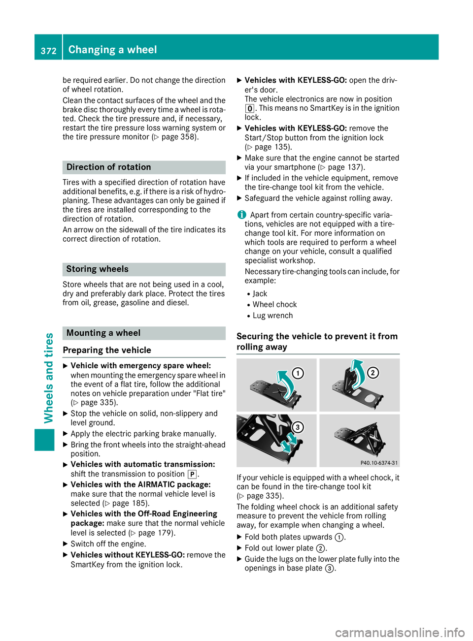
rolling away If your vehicle is equipped with a wheel chock, it
can be found in the tire-change tool kit
(Y page 335).
The folding wheel chock is an additional safety
measure to prevent the vehicle from rolling
away, for example when changing a wheel.
X Fold both plates upwards 0043.
X Fold out lower plate 0044.
X Guide the lugs on the lower plate fully into the
openings in base plate 0087.372
Changing a wheelWheels and tires
Page 375 of 398

X
Place chocks or other suitable items under
the front and rear of the wheel that is diago-
nally opposite the wheel you wish to change.
Raising the vehicle G
WARNING
If you do not position the jack correctly at the appropriate jacking point of the vehicle, the
jack could tip over with the vehicle raised.
There is a risk of injury.
Only position the jack at the appropriate jack-
ing point of the vehicle. The base of the jack
must be positioned vertically, directly under
the jacking point of the vehicle.
! Only position the jack at the appropriate
jacking point of the vehicle. Otherwise, you
could damage the vehicle.
Observe the following when raising the vehi- cle:
R To raise the vehicle, only use the vehicle-spe-
cific jack that has been tested and approved
by Mercedes-Benz. If used incorrectly, the
jack could tip over with the vehicle raised.
R The jack is designed only to raise and hold the
vehicle for a short time while a wheel is being
changed. It must not be used for performing
maintenance work under the vehicle.
R Avoid changing the wheel on uphill and down-
hill slopes.
R Before raising the vehicle, secure it from roll-
ing away by applying the parking brake and
inserting wheel chocks. Do not disengage the parking brake while the vehicle is raised.
R The jack must be placed on a firm, flat and
non-slip surface. On a loose surface, a large,
flat, load-bearing underlay must be used. On a slippery surface, a non-slip underlay must be
used, e.g. rubber mats.
R Do not use wooden blocks or similar objects
as a jack underlay. Otherwise, the jack will not
be able to achieve its load-bearing capacity
due to the restricted height.
R Make sure that the distance between the
underside of the tires and the ground does not
exceed 1.2 in (3 cm).
R Do not place your hands or feet under the
raised vehicle.
R Do not lie under the vehicle.
R Do not start the engine when the vehicle is
raised.
R Never open or close a door or the tailgate
when the vehicle is raised.
R Make sure that no persons are present in the
vehicle when the vehicle is raised. X
Using lug wrench 0043, loosen the bolts on the
wheel you wish to change by about one full
turn. Do not unscrew the bolts completely. The jacking points are located just behind the
front wheel housings and just in front of the rear
wheel housings (arrows).
X Take the ratchet wrench out of the vehicle
tool kit and place it on the hexagon nut of the
jack so that the letters AUFare visible. Changing a wheel
373Wheels and tires Z
Page 396 of 398

For further information about the maximum gra-
dient climbing ability, see (Y page 168).Trailer tow hitch
Mounting dimensions
! If you have a trailer tow hitch retrofitted,
changes to the cooling system and drive train
may be necessary, depending on the vehicle
type.
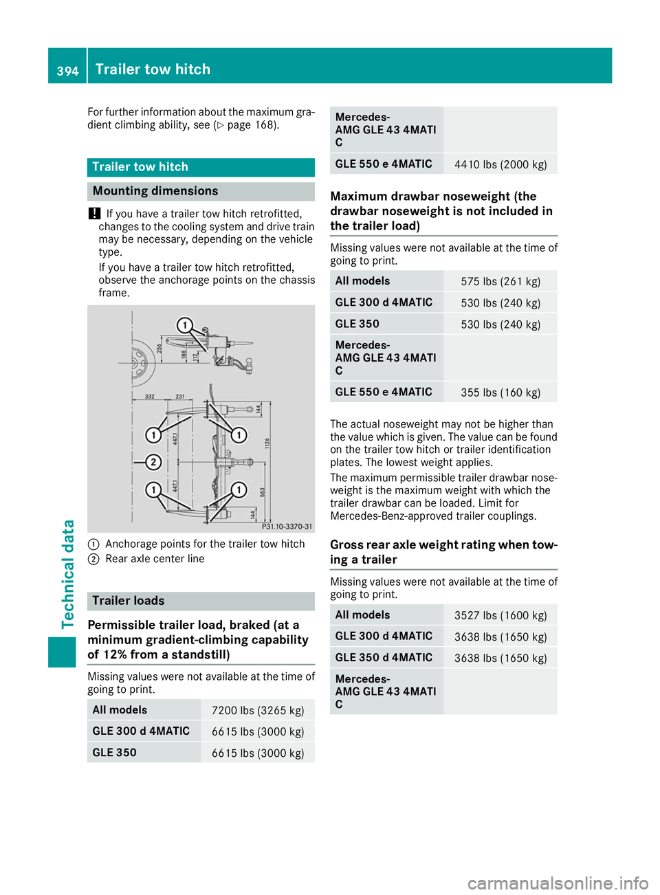
If you have a trailer tow hitch retrofitted,
observe the anchorage points on the chassis
frame. 0043
Anchorage points for the trailer tow hitch
0044 Rear axle center line Trailer loads
Permissible trailer load, braked (at a
minimum gradient-climbing capability
of 12% from a standstill) Missing values were not available at the time of
going to print. All models
7200 lbs (3265 kg)
GLE 300 d 4MATIC
6615 lbs (3000 kg)
GLE 350
6615 lbs (3000 kg) Mercedes-
AMG GLE 43 4MATI
C GLE 550 e 4MATIC
4410 lbs (2000 kg)
Maximum drawbar noseweight (the
drawbar noseweight is not included in
the trailer load)
Missing values were not available at the time of
going to print. All models
575 lbs (261 kg)
GLE 300 d 4MATIC
530 lbs (240 kg)
GLE 350
530 lbs (240 kg)
Mercedes-
AMG GLE 43 4MATI
C
GLE 550 e 4MATIC
355 lbs (160 kg)
The actual noseweight may not be higher than
the value which is given. The value can be found
on the trailer tow hitch or trailer identification
plates. The lowest weight applies.
The maximum permissible trailer drawbar nose-
weight is the maximum weight with which the
trailer drawbar can be loaded. Limit for
Mercedes-Benz-approved trailer couplings.
Gross rear axle weight rating when tow-
ing a trailer Missing values were not available at the time of
going to print. All models
3527 lbs (1600 kg)
GLE 300 d 4MATIC
3638 lbs (1650 kg)
GLE 350 d 4MATIC
3638 lbs (1650 kg)
Mercedes-
AMG GLE 43 4MATI
C394
Trailer tow hitchTechnical data