2019 MERCEDES-BENZ GLE COUPE air condition
[x] Cancel search: air conditionPage 334 of 370
Some tire pressure tables show only the rim
diameters instead of the full tire size, e.g. R18.
The rim diameter is part of the tire size and can
be found on the tire sidewall (Y page 342).
If the tire pressures have been set to the lower
values for lighter loads and/or lower road
speeds, the pressures should be reset to the
higher values:
R if you want to drive with an increased load
and/or
R if you want to drive at higher speeds
The tire pressures for increased loads and/or
higher road speeds, shown in the tire pressure
table, may have a negative effect on driving
comfort.
If the tire pressure is not set correctly, this can
lead to an excessive build up of heat and a sud- den loss of pressure.
For more information, contact a qualified spe-
cialist workshop. Important notes on tire pressure
G
WARNING
If the tire pressure drops repeatedly, the
wheel, valve or tire may be damaged. Tire
pressure that is too low may result in a tire
blow-out. There is a risk of an accident. R Check the tire for foreign objects.
R Check whether the wheel is losing air or the
valve is leaking.
If you are unable to rectify the damage, con-
tact a qualified specialist workshop. G
WARNING
If you fit unsuitable accessories onto tire
valves, the tire valves may be overloaded and malfunction, which can cause tire pressure
loss. Due to their design, retrofitted tire pres- sure monitors keep the tire valve open. This
can also result in tire pressure loss. There is a
risk of an accident.
Only screw the standard valve cap or other
valve caps approved by Mercedes-Benz for
your vehicle onto the tire valve.
Use a suitable pressure gauge to check the tire
pressure. The outer appearance of a tire does not permit any reliable conclusion about the tire
pressure. On vehicles equipped with the elec-
tronic tire pressure monitor, the tire pressure
can be checked in the on-board computer.
The tire temperature and pressure increase
when the vehicle is in motion. This is dependent
on the driving speed and the load.
Therefore, you should only correct tire pres-
sures when the tires are cold.
The tires are cold:
R if the vehicle has been parked with the tires
out of direct sunlight for at least three hours
and
R if the vehicle has not been driven further than
1 mile (1.6 km)
The tire temperature changes depending on the
outside temperature, the vehicle speed and the
tire load. If the tire temperature changes by
18 ‡ (10 †), the tire pressure changes by
approximately 10 kPa (0.1 bar/1.5 psi). Take
this into account when checking the pressure of
warm tires. Only correct the tire pressure if it is too low for the current operating conditions. If
you check the tire pressure when the tires are
warm, the resulting value will be higher than if
the tires were cold. This is normal. Do not
reduce the tire pressure to the value specified
for cold tires. The tire pressure would otherwise
be too low.
Observe the recommended tire pressures for
cold tires:
R on the Tire and Loading Information placard
on the B-pillar on the driver's side
R in the tire pressure table in the fuel filler flap
(Y page 143)
R printed in yellow on the rim of the emer-
gency/collapsible spare wheel (depending on
vehicle equipment) Underinflated or overinflated tires
Underinflated tires G
WARNING
Tires with pressure that is too low can over-
heat and burst as a consequence. In addition, they also suffer from excessive and/or irreg-
ular wear, which can severely impair the brak-ing properties and the driving characteristics.There is a risk of an accident. 332
Tire pressureWheels and tires
Page 339 of 370
Restarting the tire pressure monitor
When you restart the tire pressure monitor, all
existing warning messages are deleted and the
warning lamps go out. The monitor uses the cur-
rently set tire pressures as the reference values
for monitoring. In most cases, the tire pressure
monitor will automatically detect the new refer- ence values after you have changed the tire
pressure. However, you can also set reference
values manually as described here. The tire
pressure monitor then monitors the new tire
pressure values.
X Set the tire pressure to the value recommen-
ded for the corresponding driving situation on the Tire and Loading Information placard on
the driver's side B-pillar (Y page 330).
You can find more tire pressure values for
various operating conditions in the tire pres-
sure table inside the fuel filler flap
(Y page 331).
X Make sure that the tire pressure is correct on
all four wheels.
X Make sure that the SmartKey is in position 0048
in the ignition lock.
X Press the 0059or0065 button on the steering
wheel to select the Serv. Serv.menu.
X Press the 0063or0064 button to select
Tire Pressure
Tire Pressure .
X Press 0076.
The multifunction display shows the current
tire pressure for the individual tires or the
Tire pressure will be displayed Tire pressure will be displayed
after driving a few minutes after driving a few minutes message.
X Press the 0064button.
The Use
Use Current
Current Pressures
Pressures as
asNew
New Ref‐
Ref‐
erence
erence Values
Valuesmessage appears in the mul-
tifunction display.
If you wish to confirm the restart:
X Press the 0076button.
The Tire
Tire Press.
Press. Monitor
Monitor Restarted
Restarted mes-
sage appears in the multifunction display.
After driving for a few minutes, the system
checks whether the current tire pressures are
within the specified range. The new tire pres- sures are then accepted as reference values
and monitored.
If you wish to cancel the restart: X Press the 0038button.
The tire pressure values stored at the last
restart will continue to be monitored. Radio type approval for the tire pres-
sure monitor Country Radio type approval number
USA FCC ID: MRXGG4
FCC ID: MRXMC34MA4
This device complies with Part 15
of the FCC Rules. Operation is
subject to the following two con- ditions: (1) This device may not
cause harmful interference, and
(2) This device must accept any
interference received, including
interference that may cause
undesired operation. Canada IC: 2546A-GG4;
IC: 2546A- MC34MA4;
Le présent appareil est conforme
aux CNR d'Industrie Canada
applicables aux appareils radio
exempts de license. L'exploita-
tion est autorisée aux deux con-
ditions suivantes: (1) l'appareil
ne doit pas produire de brouil-
lage, et (2) l'utilisateur de l'ap-
pareil doit accepter tout brouil-
lage radioélectrique subi, même
si le brouillage est susceptible
d'en compromettre le fonc-
tionnement. Loading the vehicle
Instruction labels for tires and loads
G
WARNING
Overloaded tires can overheat, causing a
blowout. Overloaded tires can also impair the steering and driving characteristics and lead
to brake failure. There is a risk of accident.
Observe the load rating of the tires. The load
rating must be at least half of the GAWR of
your vehicle. Never overload the tires by
exceeding the maximum load.
Two instruction labels on your vehicle show the maximum possible load.
(1) The Tire and Loading Information placard is on the B-pillar on the driver's side. The Tire Loading the vehicle
337Wheels and tires Z
Page 348 of 370
Recommended tire pressures
The recommended tire pressure applies to the
tires mounted at the factory.
The Tire and Loading Information placard con-
tains the recommended tire pressures for cold
tires on a fully loaded vehicle and for the maxi-
mum permissible vehicle speed.
The tire pressure table contains the recommen- ded pressures for cold tires for various operat-
ing conditions, i.e. differing load and speed con- ditions.
Increased vehicle weight due to optional
equipment
The combined weight of all standard and
optional equipment available for the vehicle,
regardless of whether it is actually installed on
the vehicle or not.
Rim This is the part of the wheel on which the tire is
mounted.
GAWR (Gross Axle Weight Rating)
The GAWR is the maximum gross axle weight
rating. The actual load on an axle must never
exceed the gross axle weight rating. The gross
axle weight rating can be found on the vehicle
identification plate on the B-pillar on the driver's side.
Speed rating
The speed rating is part of the tire identification. It specifies the speed range for which the tire isapproved.
GTW (Gross Trailer Weight)
The GTW is the weight of a trailer including the
weight of the load, luggage, accessories etc. on the trailer.
GVW (Gross Vehicle Weight) The gross vehicle weight includes the weight of
the vehicle including fuel, tools, the spare wheel, accessories installed, occupants, luggage and
the drawbar noseweight, if applicable. The gross vehicle weight must not exceed the gross vehi-
cle weight rating GVWR as specified on the vehi-
cle identification plate on the B-pillar on the
driver's side. GVWR (Gross Vehicle Weight Rating)
The GVWR is the maximum permissible gross
weight of a fully loaded vehicle (the weight of the
vehicle including all accessories, occupants,
fuel, luggage and the drawbar noseweight, if
applicable). The gross vehicle weight rating is
specified on the vehicle identification plate on
the B-pillar on the driver's side.
Maximum loaded vehicle weight
The maximum weight is the sum of:
R the curb weight of the vehicle
R the weight of the accessories
R the load limit
R the weight of the factory installed optional
equipment
Kilopascal (kPa) Metric unit for tire pressure. 6.9 kPa corre-
sponds to 1 psi. Another unit for tire pressure is
bar. 100 kilopascals (kPa) are the equivalent of
1 bar.
Load index
In addition to the load-bearing index, the load
index may also be imprinted on the sidewall of
the tire. This specifies the load-bearing capacity more precisely.
Curb weight
The weight of a vehicle with standard equipment
including the maximum capacity of fuel, oil and
coolant. It also includes the air-conditioning sys- tem and optional equipment if these are instal-
led in the vehicle, but does not include passen-
gers or luggage.
Maximum load rating
The maximum tire load is the maximum permis- sible weight in kilograms or lbs for which a tire is
approved.
Maximum permissible tire pressure
Maximum permissible tire pressure for one tire.
Maximum load on one tire
Maximum load on one tire. This is calculated by
dividing the maximum axle load of one axle by
two. 346
All about wheels and tiresWheels and tires
Page 350 of 370
ponents may also be damaged. There is a risk
of an accident.
Rotate front and rear wheels only if the wheels
and tires are of the same dimensions.
! On vehicles equipped with a tire pressure
monitor, electronic components are located
in the wheel.
Tire-mounting tools should not be used near
the valve. This could damage the electronic
components.
Only have tires changed at a qualified spe-
cialist workshop.
Always observe the instructions and safety
notes in the "Mounting a wheel" section
(Y page 348).
The wear patterns on the front and rear tires
differ, depending on the operating conditions.
Rotate the wheels before a clear wear pattern
has formed on the tires. Front tires typically
wear more on the shoulders and the rear tires in
the center.
On vehicles that have the same size front and
rear wheels, you can rotate the wheels accord-
ing to the intervals in the tire manufacturer's
warranty book in your vehicle documents. If no
warranty book is available, the tires should be
rotated every 3,000 to 6,000 miles (5,000 to
10,000 km). Depending on tire wear, this may
be required earlier. Do not change the direction
of wheel rotation.
Clean the contact surfaces of the wheel and the brake disc thoroughly every time a wheel is rota-
ted. Check the tire pressure and, if necessary,
restart the tire pressure loss warning system or
the tire pressure monitor (Y page 334).Direction of rotation
Tires with a specified direction of rotation have
additional benefits, e.g. if there is a risk of hydro-
planing. These advantages can only be gained if the tires are installed corresponding to the
direction of rotation.
An arrow on the sidewall of the tire indicates its
correct direction of rotation. Storing wheels
Store wheels that are not being used in a cool,
dry and preferably dark place. Protect the tires
from oil, grease, gasoline and diesel. Mounting a wheel
Preparing the vehicle X
Vehicle with emergency spare wheel:
when mounting the emergency spare wheel in
the event of a flat tire, follow the additional
notes on vehicle preparation under "Flat tire" (Y page 310).
X Stop the vehicle on solid, non-slippery and
level ground.
X Apply the electric parking brake manually.
X Bring the front wheels into the straight-ahead
position.
X Vehicles with automatic transmission:
shift the transmission to position
005D.
X Vehicles with the AIRMATIC package:
make sure that the normal vehicle level is
selected (Y page 170).
X Switch off the engine.
X Vehicles without KEYLESS-GO: remove the
SmartKey from the ignition lock.
X Vehicles with KEYLESS-GO: open the driv-
er's door.
The vehicle electronics are now in position
0092. This means no SmartKey is in the ignition lock.
X Vehicles with KEYLESS-GO: remove the
Start/Stop button from the ignition lock
(Y page 127).
X Make sure that the engine cannot be started
via your smartphone (Y page 129).
X If included in the vehicle equipment, remove
the tire-change tool kit from the vehicle.
X Safeguard the vehicle against rolling away.
i Apart from certain country-specific varia-
tions, vehicles are not equipped with a tire-
change tool kit. For more information on
which tools are required to perform a wheel
change on your vehicle, consult a qualified
specialist workshop. 348
Changing a wheelWheels and tires
Page 355 of 370
The recommended pressures for various oper-
ating conditions can be found:
R on the Tire and Loading Information placard
on the B-pillar on the driver's side
R in the tire pressure table in the fuel filler flap
Observe the notes on recommended tire pres-
sures under various operating conditions
(Y page 330).
Check tire pressures regularly, and only when
the tires are cold. Comply with the maintenance recommendations of the tire manufacturer in
the vehicle document wallet.
Notes on the vehicle equipment – always equip
the vehicle:
R with tires of the same size on a given axle (left
and right)
R with the same type of tires at a given time
(summer tires, winter tires, MOExtended
tires)
i Vehicles equipped with MOExtended tires
are not equipped with a TIREFIT kit at the fac- tory. It is therefore recommended that you
additionally equip your vehicle with a TIREFIT
kit if you mount tires that do not feature run- flat properties, e.g. winter tires. A TIREFIT kit
may be obtained from a qualified specialist
workshop. Emergency spare wheel
Important safety notes
G
WARNING
The wheel or tire size as well as the tire type of the spare wheel or emergency spare wheel
and the wheel to be replaced may differ.
Mounting an emergency spare wheel may
severely impair the driving characteristics.
There is a risk of an accident.
To avoid hazardous situations:
R adapt your driving style accordingly and
drive carefully.
R never mount more than one spare wheel or
emergency spare wheel that differs in size.
R only use a spare wheel or emergency spare
wheel of a different size briefly. R
do not switch ESP ®
off.
R have a spare wheel or emergency spare
wheel of a different size replaced at the
nearest qualified specialist workshop.
Observe that the wheel and tire dimensions
as well as the tire type must be correct.
! Mercedes-AMG vehicles with
"Minispare" emergency spare wheel: only
use the "Minispare" emergency spare wheel
on the rear axle. If you mount the
"Minispare" emergency spare wheel on the
front axle, this could result in damage to the
brake system.
If a tire on the front axle is defective, an intact
wheel from the rear axle must first be
replaced with the "Minispare" emergency
spare wheel. The damaged wheel on the front
axle can then be replaced by the undamaged wheel from the rear axle.
Make sure to note the placard on the
"Minispare" emergency spare wheel.
When using an emergency spare wheel or spare wheel of a different size, you must not exceed
the maximum speed of 50 mph (80 km/h).
You should regularly check the pressure of the
emergency spare wheel, particularly prior to
long trips, and correct the pressure as neces-
sary (Y page 330). The value on the wheel is
valid.
Snow chains must not be mounted on emer-
gency spare wheels. General notes
Information regarding permitted emergency
spare wheels can be found at an authorized
Mercedes-Benz Center.
Mounting the emergency spare wheel is descri- bed under "Mounting a wheel" (Y page 348).
An emergency spare wheel may also be moun-
ted against the direction of rotation. Observe
the time restriction on use as well as the speed
limitation specified on the emergency spare
wheel.
Replace the tires after six years at the latest,
regardless of wear. This also applies to the
emergency spare wheel.
When you are driving with the collapsible spare wheel mounted, the tire pressure loss warning
system or the tire pressure monitor cannot func- Emergency spare wheel
353Wheels and tires Z
Page 366 of 370
cable regulations, as well as SAE standard J639,
must be adhered to.
Always have work on the climate control system
carried out at a qualified specialist workshop.
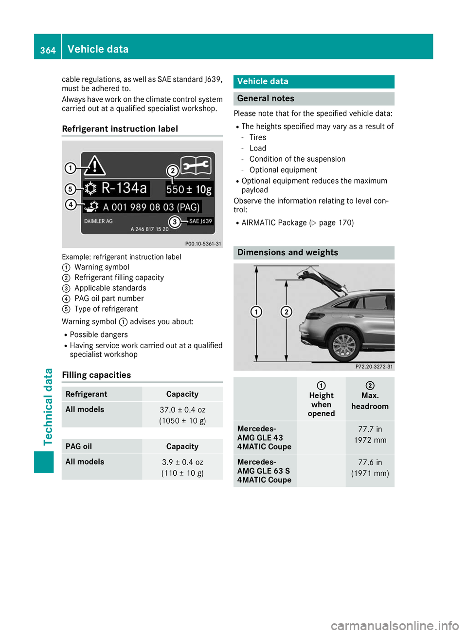
Refrigerant instruction label Example: refrigerant instruction label
0043 Warning symbol
0044 Refrigerant filling capacity
0087 Applicable standards
0085 PAG oil part number
0083 Type of refrigerant
Warning symbol 0043advises you about:
R Possible dangers
R Having service work carried out at a qualified
specialist workshop
Filling capacities Refrigerant Capacity
All models
37.0 ± 0.4 oz
(1050 ± 10 g) PAG oil Capacity
All models
3.9 ± 0.4 oz
(110 ± 10 g) Vehicle data
General notes
Please note that for the specified vehicle data: R The heights specified may vary as a result of
- Tires
- Load
- Condition of the suspension
- Optional equipment
R Optional equipment reduces the maximum
payload
Observe the information relating to level con-
trol:
R AIRMATIC Package (Y page 170) Dimensions and weights
0043 0043
Height when
opened 0044
0044
Max.
headroom Mercedes-
AMG GLE 43
4MATIC Coupe
77.7 in
1972 mm Mercedes-
AMG GLE 63 S
4MATIC Coupe
77.6 in
(1971 mm) 364
Vehicle dataTechnical data
Page 368 of 370
The vehicle widths specified may differ depend-
ing on:
R Tires
R Load
R Condition of the suspension Vehicle data for off-road driving
Maximum water depth
! The water depth must not exceed the speci-
fied value. Note that the permissible water
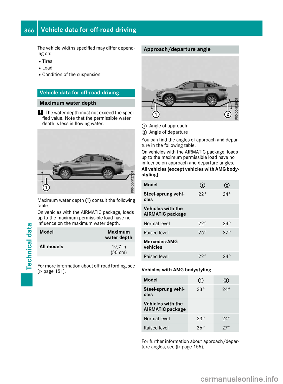
depth is less in flowing water. Maximum water depth
0043consult the following
table.
On vehicles with the AIRMATIC package, loads
up to the maximum permissible load have no
influence on the maximum water depth. Model Maximum
water depth All models
19.7 in
(50 cm) For more information about off-road fording, see
(Y page 151). Approach/departure angle
0043
Angle of approach
0044 Angle of departure
You can find the angles of approach and depar-
ture in the following table.
On vehicles with the AIRMATIC package, loads
up to the maximum permissible load have no
influence on approach and departure angles.
All vehicles (except vehicles with AMG body- styling) Model
0043 0043 0044
0044
Steel-sprung vehi-
cles
22° 24°
Vehicles with the
AIRMATIC package
Normal level 22° 24°
Raised level 26° 27°
Mercedes-AMG
vehicles
Raised level 22° 24°
Vehicles with AMG bodystyling
Model
0043 0043 0044
0044
Steel-sprung vehi-
cles
23° 24°
Vehicles with the
AIRMATIC package
Normal level 23° 24°
Raised level 26° 27°
For further information about approach/depar-
ture angles, see (Y
page 155).366
Vehicle data for off-road drivingTechnical data