2019 MERCEDES-BENZ GLC SUV display
[x] Cancel search: displayPage 270 of 673
Yo
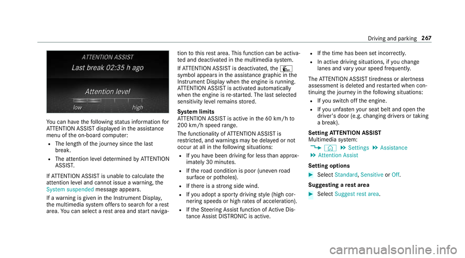
u can ha vethefo llowing status information for
AT TENTION ASSIST displa yed in the assis tance
menu of the on-board computer:
R The length of the journey since the last
break.
R The attention le vel de term ined byATTENTION
ASSIS T.
If AT TENTION ASSIST is unable tocalculate the
attention le vel and cannot issue a warning, the
System suspended messageappears.
If a warning is given in the Instrument Displa y,
th e multimedia sy stem of fers to sear chfor a rest
area. You can select a rest area and start naviga‐ tion
tothis rest area. This function can be activa‐
te d and deactivated in the multimedia sy stem.
If AT TENTION ASSIST is deactivated, theÛ
symbol appears in the assis tance graphic in the
Instrument Display when the engine is running.
AT TENTION ASSIST is activated automatically
when the engine is re-sta rted. The last selected
sensitivity le velre mains stored.
Sy stem limits
AT TENTION ASSIST is active in the 60 km/h to
200 km/h speed range.
The functionality of ATTENTION ASSIST is
re stricted, and warnings may be dela yed or not
occur at all in thefo llowing situations:
R Ifyo u ha vebeen driving for less than appr ox‐
imately 30 minutes.
R Ifth ero ad condition is poor (une venro ad
sur face or po tholes).
R Ifth ere is a strong side wind.
R Ifyo u adopt a sporty driving style (high cor‐
nering speeds or high rates of acceleration).
R Ifth eSt eering Assist function of Active Dis‐
ta nce Assi stDISTRONIC is acti ve.R
Ifth e time has been set incor rectly.
R In acti vedriving situations, if youch ange
lanes and vary your speed frequentl y.
The ATTENTION ASSIST tiredness or alertness
assessment is dele ted and restar ted when con‐
tinuing the journey in thefo llowing situations:
R Ifyo u swit choff the engine.
R Ifyo u unfas tenyo ur seat belt and open the
driver's door (e.g. changing drivers or taking
a break).
Setting ATTENTION ASSI ST
Multimedia sy stem:
4 © 5
Settings 5
Assistance
5 Attention Assist
Setting options #
Select Standard, SensitiveorOff.
Suggesting a rest area #
Select Suggest rest area . Driving and parking
267
Page 271 of 673
#
Activate or deacti vate the function.
If AT TENTION ASSIST de tects fatigue or
increasing la ckof attention, it suggests a
re st area in the vicinit y. #
Select the sugges tedre st area.
Yo u are guided tothe selected rest area. Tr
af fic Sign Assist Fu
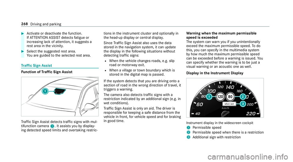
nction of Traf fic Sign Assist Tr
af fic Sign Assi stdetects traf fic signs wi thmul‐
tifunction camera 1. It assistsyo uby display‐
ing de tected speed limits and overtaking restric‐ tions in
the instrument clus ter and optionally in
th e head-up display or cent ral displa y.
Since Traf fic Sign Assi stalso uses the data
st ored in the navigation sy stem, it can update
th e display in thefo llowing situations without
de tecting traf fic signs:
R When theve hicle changes roads, e.g. slip
ro ad or mo torw ay ex it.
R When a village or town boundary which is
st ored in the digital map is passed.
If th e sy stem de tects that you are driving on to a
section of road in the wrong direction of tr avel, it
triggers a warning.
The camera also de tects traf fic signs wi th a
re striction indicated byan additional sign (e.g. in
we t conditions).
Tr af fic Sign Assi stis only an aid. The driver is
re sponsible forke eping a safe dis tance from the
ve hicle in front, forve hicle speed and for braking
in good time. Wa
rning when the maximum permissible
speed is exceeded
The sy stem can warnyou if you unin tentionally
exc eed the maximum permissible speed. Todo
th is, you can specify in the multimedia sy stem
by how much the maximum permissible speed
can be exceeded before a warning is issued. Yo u
can specify whe ther thewa rning is tobe just a
visual warning or an acoustic one as well.
Display in the Instrument Display In
stru ment display in the widescreen cockpit
1 Perm issible speed
2 Perm issible speed when there is a restriction
3 Additional sign with restriction 268
Driving and pa rking
Page 272 of 673
Tr
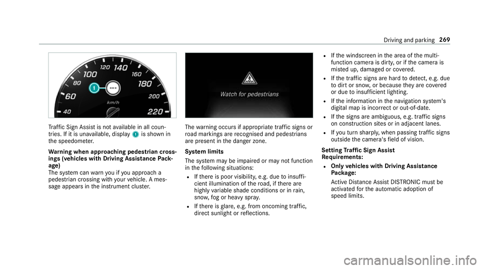
af fic Sign Assi stis not available in all coun‐
tries. If it is una vailable, display 1is shown in
th e speedome ter.
Wa rning when app roaching pedestrian cross‐
ings (vehicles with Driving AssistancePack‐
age)
The sy stem can warnyou if you approach a
pedestrian crossing with your vehicle. A mes‐
sage appears inthe instrument clus ter. The
warning occurs if appropriate traf fic signs or
ro ad markings are recognised and pedestrians
are present in the danger zone.
Sy stem limits
The sy stem may be impaired or may not function
in thefo llowing situations:
R Ifth ere is poor visibility, e.g. due toinsuf fi‐
cient illumination of thero ad, if there are
highly variable shade conditions or in rain,
sno w,fog or heavy spr ay.
R Ifth ere is glare, e.g. from oncoming traf fic,
di re ct sunlight or reflections. R
Ifth e windscreen in the area of the multi‐
function camera is dirty, or if the camera is
mis ted up, damaged or co vered.
R Ifth e tra ffic signs are hard todetect, e.g. due
to dirt or sno w,or because they are co vered
or due toinsuf ficient lighting.
R Ifth e information in the navigation sy stem's
digital map is incor rect or out-of-da te.
R Ifth e signs are ambiguous, e.g. tra ffic signs
on con stru ction sites or in adjacent lanes.
R Ifyo u turn sharpl y,when passing traf fic signs
outside the camera's field of vision.
Setting Traf fic Sign Assist
Requ irements:
R Only vehicles with Driving Assistance
Pa ckage:
Ac tive Dis tance Assi stDISTRONIC mu stbe
activated forth e automatic adoption of
speed limits. Driving and parking
269
Page 273 of 673
Multimedia sy
stem:
4 © 5
Settings 5
Assistance
5 Traffic Sign Assist
Ac tivating/deactivating automatic adoption
of speed limits (only vehicles with Driving
Assistance Package) #
Select Adopt limit. #
Activate or deacti vate the function.
The speed limits de tected byTraf fic Sign
Assi stare automatically adop tedby Active
Dis tance Assi stDISTRONIC.
% If one of thefo llowing sy stems is activated,
th e speed de tected can be manually adop ted
as the speed limit:
R Active Dis tance Assi stDISTRONIC
R Cruise control
R Variable limiter
Fu rther information (/ page 230).
Displaying de tected traf fic signs in the
medi a display #
Select Display in head unit. #
Activate or deacti vate the function.
Ad justing the type of warning #
Select Visual & audible ,Visual orNone.
Ad justing the warning threshold
This value de term ines the speed at which a
wa rning is issued when exceeded. #
Select Warning threshold. #
Set the desired speed. Blind Spot Assist and
Active Blind Spot
Assi stwith exitwa rning Fu
nction of Blind Spot Assist and Active
Blind Spot Assi stwith exitwa rning
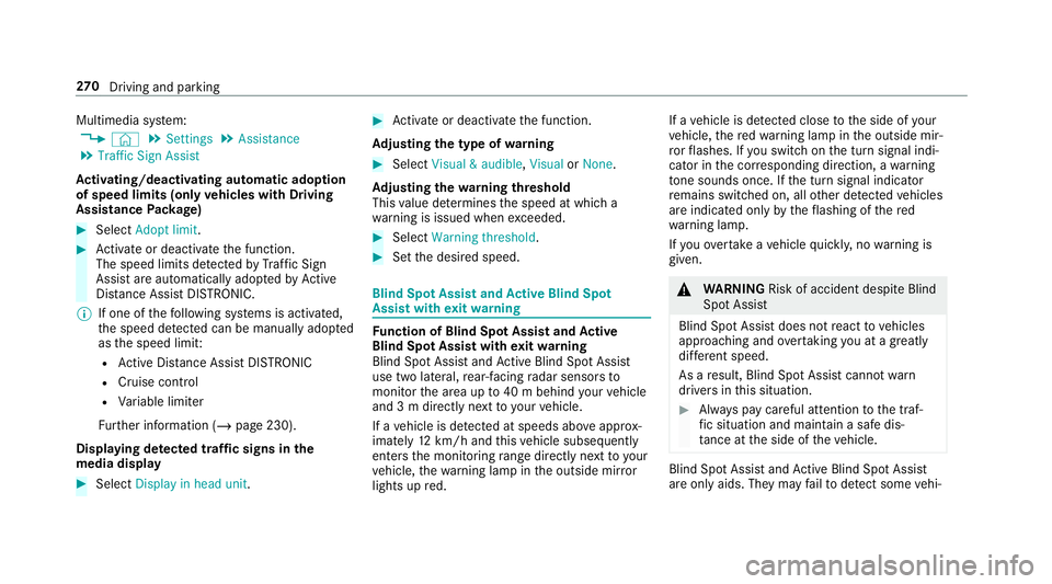
Blind Spot Assist and Active Blind Spot Assi st
use two lateral, rear-facing radar sensors to
monitor the area up to40 m behind your vehicle
and 3 m directly next to yourvehicle.
If a vehicle is de tected at speeds ab ove appr ox‐
imately 12km/h and this vehicle subsequently
enters the monitoring range di rectly next to your
ve hicle, thewa rning lamp in the outside mir ror
lights up red. If a
vehicle is de tected close tothe side of your
ve hicle, there dwa rning lamp in the outside mir‐
ro rflashes. If you swit chon the turn signal indi‐
cator in the cor responding direction, a warning
to ne sounds once. If the turn signal indicator
re mains switched on, all other de tected vehicles
are indicated only bytheflashing of thered
wa rning lamp.
If yo uove rtake a vehicle quickl y,no warning is
given. &
WARNING Risk of accident despi teBlind
Spot Assi st
Blind Spot Assi stdoes not react tovehicles
approaching and overtaking you at a greatly
di fferent speed.
As a result, Blind Spot Assist cannot warn
drivers in this situation. #
Alw ays pay careful attention tothe traf‐
fi c situation and maintain a safe dis‐
ta nce at the side of theve hicle. Blind Spot Assist and
Active Blind Spot Assi st
are on lyaids. They may failto detect some vehi‐ 270
Driving and pa rking
Page 279 of 673
Extends/r
etra cts the ball neck fully electri‐
cally &
WARNING Risk of accident due tothe
ball neck not being engaged
If th e ball neck is not engaged, the trailer
may come loose. #
Make sure that the ball neck securely
engages and loc ksinto place. *
NO
TEDama getothe all-electric trailer
hitch due toadditional pressure The all-electric trailer hit
chcould be mechan‐
ically damaged byapplying additional pres‐
sure when the ball neck is being extended or
re tracted. #
Do not ma kethe ball neck extend/
re tract faster by applying additional
pressure. Re
quirements:
R The vehicle is secured against rolling away.
R The range of mo vement is clear. R
The trailer cables or adapte r plugs havebeen
re mo ved.
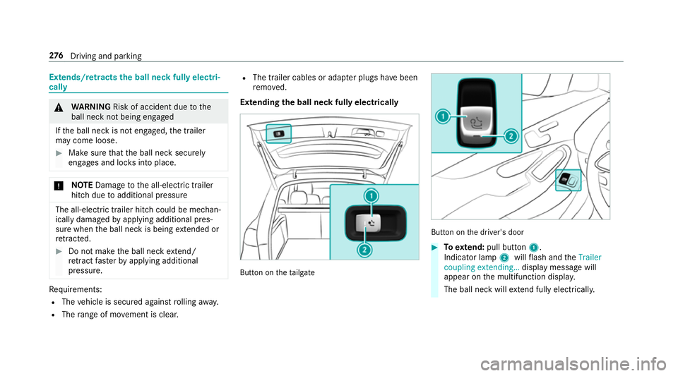
Extending the ball neck fully electrically But
ton on theta ilgate But
ton on the driver's door #
Toextend: pull button 1.
Indicator lamp 2willflash and theTrailer
coupling extending… display message will
appear on the multifunction displa y.
The ball neck will extend fully electrically. 276
Driving and pa rking
Page 280 of 673
#
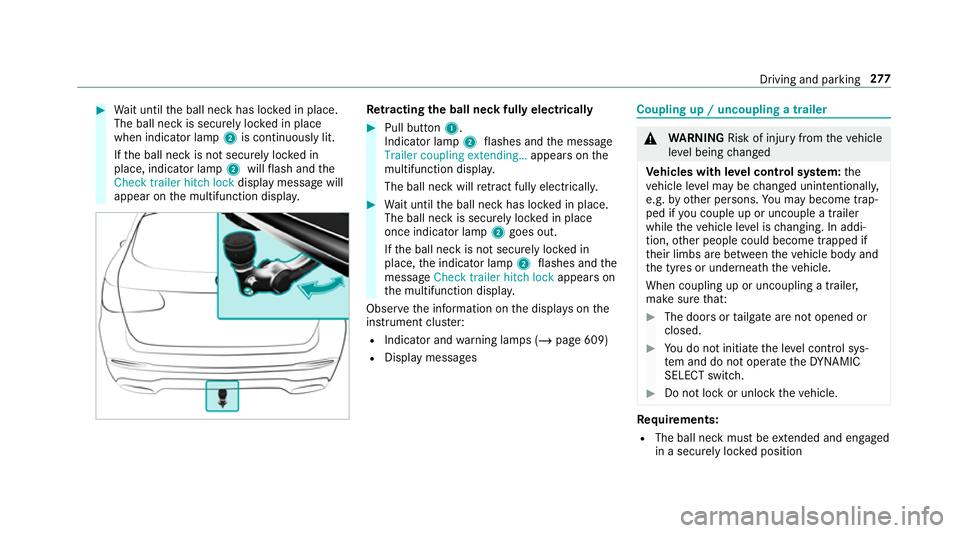
Wait until the ball neck has loc ked in place.
The ball neck is securely loc ked in place
when indicator lamp 2is continuously lit.
If th e ball neck is not securely loc ked in
place, indicator lamp 2willflash and the
Check trailer hitch lock displaymessa gewill
appear on the multifunction displa y. Re
tracting the ball ne ckfully electrical ly #
Pull button 1.
Indicator lamp 2flashes and the message
Trailer coupling extending… appears onthe
multifunction displa y.
The ball neck will retract fully electrically. #
Wait until the ball neck has loc ked in place.
The ball neck is securely loc ked in place
once indicator lamp 2goes out.
If th e ball neck is not securely loc ked in
place, the indicator lamp 2flashes and the
messa geCheck trailer hitch lock appears on
th e multifunction displa y.
Obser vethe information on the displa yson the
instrument clus ter:
R Indicator and warning lamps (/ page 609)
R Display messages Coupling up / uncoupling a trailer
&
WARNING Risk of inju ryfrom theve hicle
le ve l being changed
Ve hicles with le vel control sy stem: the
ve hicle le vel may be changed unin tentional ly,
e.g. by ot her persons. You may become trap‐
ped if you couple up or uncouple a trailer
while theve hicle le vel is changing. In addi‐
tion, other people could become trapped if
th eir limbs are between theve hicle body and
th e tyres or underneath theve hicle.
When coupling up or uncoupling a trailer,
make sure that: #
The doors or tailgate are not opened or
closed. #
You do not initiate the le vel control sys‐
te m and do not operate theDY NA MIC
SELECT switch. #
Do not lock or unlock theve hicle. Re
quirements:
R The ball neck must be extended and engaged
in a secu rely loc ked position Driving and parking
277
Page 281 of 673
Tr
ailers with a 7-pin plug can be connec tedto
th eve hicle with thefo llowing adap ters:
R Adapter plug
R Adapter cable
The trailer will be cor rectly de tected bytheve hi‐
cle only if thefo llowing conditions are me t:
R The trailer is connected cor rectly
R The trailer lighting sy stem is in working order
The functions of thefo llowing sy stems are af fec‐
te dby a cor rectly connected traile r:
R Active Lane Keeping Assist
R ESP ®
trailer stabilisation
R Parking Assist PARKTRONIC
R Active Parking Assist
R Blind Spot Assist or Active Blind Spot Assi st
R Drive AwayAssi st
R Cross Traf fic Alert
R Trailer Manoeuv ring Assi st
R Reversing camera
R 360° camera Coupling up a trailer
* NO
TEDama getotheve hicle battery due
to full discharge Charging
the trailer battery using the po wer
supply of the trailer can damage theve hicle
batter y. #
Do not use theve hicle's po wer supply
to charge the trailer batter y. #
Remo vethe co ver from the ball head and
st ore it in a safe place (/ page116). #
Position the trailer on a le vel sur face behind
th eve hicle and couple it up totheve hicle. #
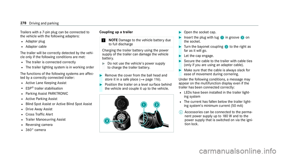
Open the soc ket cap. #
Inse rtthe plug with lug 1in groo ve3 on
th e soc ket. #
Turn the ba yonet coupling 2totheright as
fa r as it will go. #
Let the cap engage. #
Secure the cable tothe trailer with cable ties
(only if you are using an adap ter cable). #
Make sure that the cable is alw ays slack for
ease of mo vement during cornering.
Under thefo llowing conditions, a message may
appear on the multifunction display even if the
trailer has been connected cor rectly:
R LEDs ha vebeen ins talled in the trailer light‐
ing sy stem
R The cur rent has fallen below the trailer light‐
ing sy stem's minimum cur rent (50 mA)
% Accessories can be connected tothe perma‐
nent po wer supp lyup to180 W and tothe
po we r supp lythat is swit ched on via the igni‐
tion loc k. 278
Driving and pa rking
Page 286 of 673
Instrument display
overview
Mercedes-AMG vehicles: be sure toobser ve
th e no tes in the Supplement. Otherwise, you
may failto recognise dangers.
Plug-in hybrid: be sure toobser vethe no tes in
th e Supplement. Otherwise, you may failto rec‐
ognise dangers. &
WARNING Risk of accident due toan
instrument display malfunction
If th e Instrument Display has failed or mal‐
functioned, you may not recognise function
re strictions applying tosaf etyre leva nt sys‐
te ms.
The operating saf ety of your vehicle may be
impaired. #
Drive on carefull y. #
Have theve hicle checked immediately
at a qualified specialist workshop. If
th e operating saf ety of your vehicle is
impaired, park theve hicle immediately and
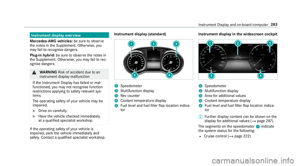
safel y.Con tact a qualified specialist workshop. Instrument display (standard)
1
Speedome ter
2 Multifunction display
3 Rev counter
4 Coolant temp erature display
5 Fuel le vel and fuel filler flap location indica‐
tor Instrument display in
the widescreen cockpit 1
Speedome ter
2 Multifunction display
3 Area for additional values
4 Coolant temp erature display
5 Fuel le vel and fuel filler flap location indica‐
tor
% Further display content can be shown on the
display for additional values (/ page 287).
The segments on the speedome ter1 indica te
th e sy stem status forth efo llowing:
R Cruise control (/ page 222) Instrument Display and on-board computer
283