2019 MERCEDES-BENZ GLC SUV light
[x] Cancel search: lightPage 260 of 673
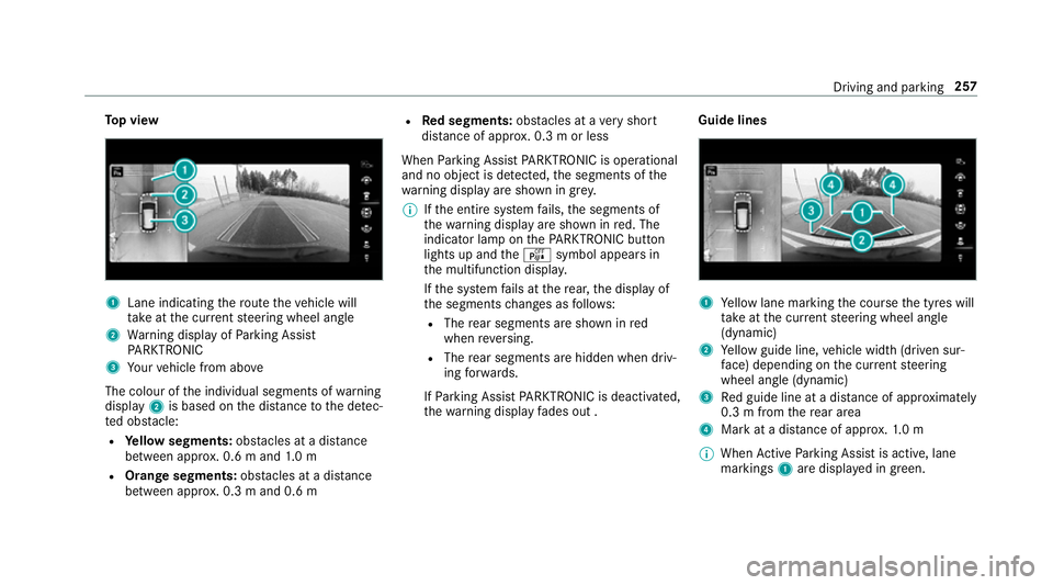
To
p view 1
Lane indicating thero ute theve hicle will
ta ke atthe cur rent steering wheel angle
2 Warning display of Parking Assist
PA RKTRONIC
3 Your vehicle from abo ve
The colour of the individual segments of warning
display 2is based on the dis tance tothe de tec‐
te d obs tacle:
R Yellow segments: obstacles at a di stance
between appr ox. 0.6 m and 1.0 m
R Orange segments: obstacles at a di stance
between appr ox. 0.3 m and 0.6 m R
Red segments: obstacles at a very short
dis tance of appr ox. 0.3 m or less
When Parking Assist PARKTRONIC is operational
and no object is de tected, the segments of the
wa rning display are shown in gr ey.
% Ifth e entire sy stem fails, the segments of
th ewa rning display are shown in red. The
indicator lamp on thePA RKTRONIC but ton
lights up and theé symbol appears in
th e multifunction displa y.
If th e sy stem fails at there ar, the display of
th e segments changes as follo ws:
R The rear segments are shown in red
when reve rsing.
R The rear segments are hidden when driv‐
ing forw ards.
If Pa rking Assist PARKTRONIC is deacti vated,
th ewa rning display fades out . Guide lines
1
Yellow lane marking the course the tyres will
ta ke atthe cur rent steering wheel angle
(dynamic)
2 Yellow guide line, vehicle width (driven sur‐
fa ce) depending on the cur rent steering
wheel angle (dynamic)
3 Red guide line at a dis tance of appr oximately
0.3 m from there ar area
4 Mark at a distance of appr ox.1. 0 m
% When Active Parking Assist is active, lane
markings 1are displa yed in green. Driving and parking
257
Page 262 of 673
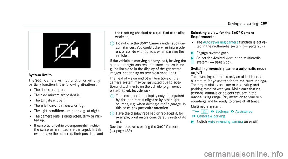
Sy
stem limits
The 360° Camera will not function or will only
partially function in thefo llowing situations:
R The doors are open.
R The side mir rors are folded in.
R The tailgate is open.
R There is heavy rain, snow or fog.
R The light conditions are poor, e.g. at night.
R The camera lens is obstructed, dirty or mis‐
te d up.
R If cameras or vehicle components in which
th e cameras are fitted are dama ged. In this
eve nt, ha vethe cameras, their positions and th
eir setting checked at a qualified specialist
wo rkshop.
% Do not use the 360° Camera under such cir‐
cums tances. You could otherwise injure oth‐
ers or collide with objects when parking the
ve hicle.
If th eve hicle is car rying a heavy load, leaving the
st andard height can result in inaccuracies in the
guide lines and in the display of thege nerated
ima ges, depending on tech nical conditions.
The field of vision and other functions of the
came rasystem may be restricted due toaddi‐
tional attachments on theve hicle (e.g. licence
plate brac ket, bicycle rack ).
% The contrast of the display may be impaired
by abrupt direct sunlight or by other light
sources, e.g. when driving out of a garage . In
th is case, pay particular attention.
% Have the display repaired or replaced if, for
ex ample, pixel er rors considerably restrict its
use.
See the no tes on cleaning the 360° Camera
(/ page 489). Selecting a view
for the 360° Camera
Re quirements:
R The Auto reversing camera function is activa‐
te d in the multimedia sy stem (/ page 259). #
Enga gereve rsege ar. #
Select the desired view in the multimedia
sy stem (/ page 256).
Switching reve rsing camera automatic mode
on/off
The reve rsing camera is only an aid. It is not a
substitute foryo ur attention tothe sur roundings.
The responsibility for safe manoeuvring and
parking remains with you. Make sure that no
persons, animals or objects etc. are in the
manoeuvring range. Pay attention to your sur‐
ro undings and be ready tobrake at all times.
Multimedia sy stem:
4 © 5
Settings 5
Assistance
5 Camera & parking #
Switch Auto reversing camera on or off. Driving and parking
259
Page 272 of 673
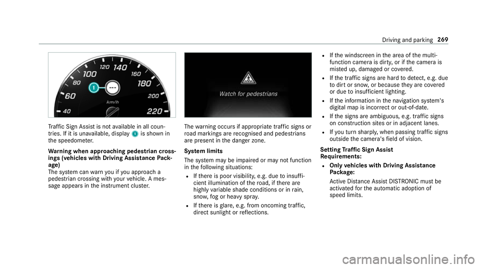
Tr
af fic Sign Assi stis not available in all coun‐
tries. If it is una vailable, display 1is shown in
th e speedome ter.
Wa rning when app roaching pedestrian cross‐
ings (vehicles with Driving AssistancePack‐
age)
The sy stem can warnyou if you approach a
pedestrian crossing with your vehicle. A mes‐
sage appears inthe instrument clus ter. The
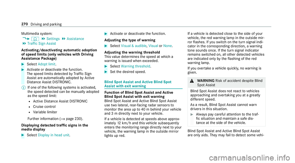
warning occurs if appropriate traf fic signs or
ro ad markings are recognised and pedestrians
are present in the danger zone.
Sy stem limits
The sy stem may be impaired or may not function
in thefo llowing situations:
R Ifth ere is poor visibility, e.g. due toinsuf fi‐
cient illumination of thero ad, if there are
highly variable shade conditions or in rain,
sno w,fog or heavy spr ay.
R Ifth ere is glare, e.g. from oncoming traf fic,
di re ct sunlight or reflections. R
Ifth e windscreen in the area of the multi‐
function camera is dirty, or if the camera is
mis ted up, damaged or co vered.
R Ifth e tra ffic signs are hard todetect, e.g. due
to dirt or sno w,or because they are co vered
or due toinsuf ficient lighting.
R Ifth e information in the navigation sy stem's
digital map is incor rect or out-of-da te.
R Ifth e signs are ambiguous, e.g. tra ffic signs
on con stru ction sites or in adjacent lanes.
R Ifyo u turn sharpl y,when passing traf fic signs
outside the camera's field of vision.
Setting Traf fic Sign Assist
Requ irements:
R Only vehicles with Driving Assistance
Pa ckage:
Ac tive Dis tance Assi stDISTRONIC mu stbe
activated forth e automatic adoption of
speed limits. Driving and parking
269
Page 273 of 673
Multimedia sy
stem:
4 © 5
Settings 5
Assistance
5 Traffic Sign Assist
Ac tivating/deactivating automatic adoption
of speed limits (only vehicles with Driving
Assistance Package) #
Select Adopt limit. #
Activate or deacti vate the function.
The speed limits de tected byTraf fic Sign
Assi stare automatically adop tedby Active
Dis tance Assi stDISTRONIC.
% If one of thefo llowing sy stems is activated,
th e speed de tected can be manually adop ted
as the speed limit:
R Active Dis tance Assi stDISTRONIC
R Cruise control
R Variable limiter
Fu rther information (/ page 230).
Displaying de tected traf fic signs in the
medi a display #
Select Display in head unit. #
Activate or deacti vate the function.
Ad justing the type of warning #
Select Visual & audible ,Visual orNone.
Ad justing the warning threshold
This value de term ines the speed at which a
wa rning is issued when exceeded. #
Select Warning threshold. #
Set the desired speed. Blind Spot Assist and
Active Blind Spot
Assi stwith exitwa rning Fu
nction of Blind Spot Assist and Active
Blind Spot Assi stwith exitwa rning
Blind Spot Assist and Active Blind Spot Assi st
use two lateral, rear-facing radar sensors to
monitor the area up to40 m behind your vehicle
and 3 m directly next to yourvehicle.
If a vehicle is de tected at speeds ab ove appr ox‐
imately 12km/h and this vehicle subsequently
enters the monitoring range di rectly next to your
ve hicle, thewa rning lamp in the outside mir ror
lights up red. If a
vehicle is de tected close tothe side of your
ve hicle, there dwa rning lamp in the outside mir‐
ro rflashes. If you swit chon the turn signal indi‐
cator in the cor responding direction, a warning
to ne sounds once. If the turn signal indicator
re mains switched on, all other de tected vehicles
are indicated only bytheflashing of thered
wa rning lamp.
If yo uove rtake a vehicle quickl y,no warning is
given. &
WARNING Risk of accident despi teBlind
Spot Assi st
Blind Spot Assi stdoes not react tovehicles
approaching and overtaking you at a greatly
di fferent speed.
As a result, Blind Spot Assist cannot warn
drivers in this situation. #
Alw ays pay careful attention tothe traf‐
fi c situation and maintain a safe dis‐
ta nce at the side of theve hicle. Blind Spot Assist and
Active Blind Spot Assi st
are on lyaids. They may failto detect some vehi‐ 270
Driving and pa rking
Page 275 of 673
Fu
nction of brake application (Active Blind
Spot Assist)
% The brake application function is only availa‐
ble forve hicles with a Driving Assis tance
Pa ckage.
If Ac tive Blind Spot Assi stdetects a risk of a side
impact in the monitoring range, a cou rse-cor‐
re cting brake application is car ried out. This is
designed tohelp youavo id a collision.
The course-cor recting brake application is availa‐
ble in the speed range between appr oximately
30 km/h and 200 km/h. &
WARNING Risk of accident despi te
brake application of Active Blind Spot
Assi st
A cou rse-co rrecting brake application cann ot
alw ays pr event a collision. #
Alw aysst eer, brake or accelera teyour‐
self, especially if Active Blind Spot
Assi stwa rnsyo u or makes a course-
co rrecting brake application. #
Alw ays maintain a safe dis tance at the
sides. &
WARNING Risk of accident despi te
Ac tive Blind Spot Assi st
Ac tive Blind Spot Assi stdoes not react tothe
fo llowing:
R ifve hicles overtake too closely on the
side, placing them in the blind spot area
R vehicles approaching and overtaking you
at a greatly di fferent speed
As a result, Active Blind Spot Assi stmay nei‐
th er give warnings nor inter vene in su chsit‐
uations. #
Alw ays pay careful attention tothe traf‐
fi c situation and maintain a safe dis‐
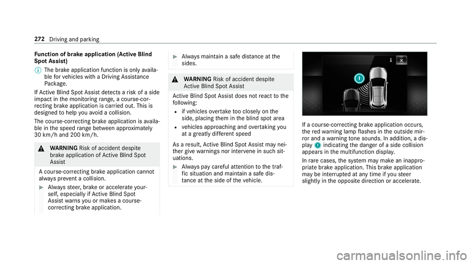
ta nce at the side of theve hicle. If a course-cor
recting brake application occu rs,
th ere dwa rning lamp flashes in the outside mir‐
ro r and a warning tone sounds. In addition, a dis‐
pl ay 1 indicating the danger of a side collision
appears in the multifunction displa y.
In rare cases, the sy stem may make an inappro‐
priate brake application. This brake application
may be inter rupte d at any time if yousteer
slightly in the opposite direction or accelera te.272
Driving and pa rking
Page 278 of 673
R
Ifth e car riag ewa y is very nar row and wind‐
ing.
Ac tivating/deactivating Active Lane Keeping
Assist
Multimedia sy stem:
4 © 5
Settings 5
Quick access
5 Active Lane Keeping Assist #
Activate or deacti vate the function.
Setting Active Lane Keeping Assist
Multimedia sy stem:
4 © 5
Settings 5
Assistance
5 Active Lane Keeping Assist
Setting the sensitivity
% The availability of this function is dependent
on the count ry. #
Select Standard ,Sensitive orOff.
Ac tivating/deactivating the haptic warning #
Select Warning.
Ac tivate or deacti vate the function. Tr
ailer hitch Note
s on trailer operation Mercedes‑AMG
vehicles: be sure toobser ve
th e no tes in the Supplement. Otherwise, you
may failto recognise dangers.
Plug-in hybrid: obser vethe no tes in the Supple‐
ment. Otherwise, you may failto recognise dan‐
ge rs.
Obser vethefo llowing no tes on theto ngue
we ight:
R Do not use a tongue weight that exceeds or
fa lls below the permissible tongue weight
R Use a tongue weight as close as possible to
th e maximum tongue weight
Do not exceed thefo llowing values:
R Perm issible trailer load
R Perm issible rear axle load of theto wing vehi‐
cle
R Perm issible gross mass of theto wing vehicle
R Perm issible gross mass of the trailer
R Maximum permissible speed of the trailer Ensure
thefo llowing before starting a journey:
R The tyre pressure on there ar axle of theto w‐
ing vehicle is set for a maximum load
R The lighting of the connected trailer is opera‐
tional
R Vehicles without LED headlamps or MUL‐
TIBEAM LED headlamps: the headlamps
ha ve been set cor rectly
In theeve nt of increased rear axle load, the car/
trailer combination may not exceed a maximum
speed of 100 km/h forre asons concerning the
operating permit. This also applies in countri es
in which the permissible maximum speed for
car/trailer combinations is ab ove100 km/h.
% When you are reve rsing with a trailer,
re member touse theTr ailer Manoeuvring
Assist function (/ page 251). Driving and parking
275
Page 281 of 673
Tr
ailers with a 7-pin plug can be connec tedto
th eve hicle with thefo llowing adap ters:
R Adapter plug
R Adapter cable
The trailer will be cor rectly de tected bytheve hi‐
cle only if thefo llowing conditions are me t:
R The trailer is connected cor rectly
R The trailer lighting sy stem is in working order
The functions of thefo llowing sy stems are af fec‐
te dby a cor rectly connected traile r:
R Active Lane Keeping Assist
R ESP ®
trailer stabilisation
R Parking Assist PARKTRONIC
R Active Parking Assist
R Blind Spot Assist or Active Blind Spot Assi st
R Drive AwayAssi st
R Cross Traf fic Alert
R Trailer Manoeuv ring Assi st
R Reversing camera
R 360° camera Coupling up a trailer
* NO
TEDama getotheve hicle battery due
to full discharge Charging
the trailer battery using the po wer
supply of the trailer can damage theve hicle
batter y. #
Do not use theve hicle's po wer supply
to charge the trailer batter y. #
Remo vethe co ver from the ball head and
st ore it in a safe place (/ page116). #
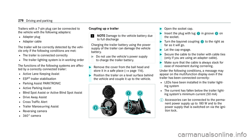
Position the trailer on a le vel sur face behind
th eve hicle and couple it up totheve hicle. #
Open the soc ket cap. #
Inse rtthe plug with lug 1in groo ve3 on
th e soc ket. #
Turn the ba yonet coupling 2totheright as
fa r as it will go. #
Let the cap engage. #
Secure the cable tothe trailer with cable ties
(only if you are using an adap ter cable). #
Make sure that the cable is alw ays slack for
ease of mo vement during cornering.
Under thefo llowing conditions, a message may
appear on the multifunction display even if the
trailer has been connected cor rectly:
R LEDs ha vebeen ins talled in the trailer light‐
ing sy stem
R The cur rent has fallen below the trailer light‐
ing sy stem's minimum cur rent (50 mA)
% Accessories can be connected tothe perma‐
nent po wer supp lyup to180 W and tothe
po we r supp lythat is swit ched on via the igni‐
tion loc k. 278
Driving and pa rking
Page 290 of 673
Setting
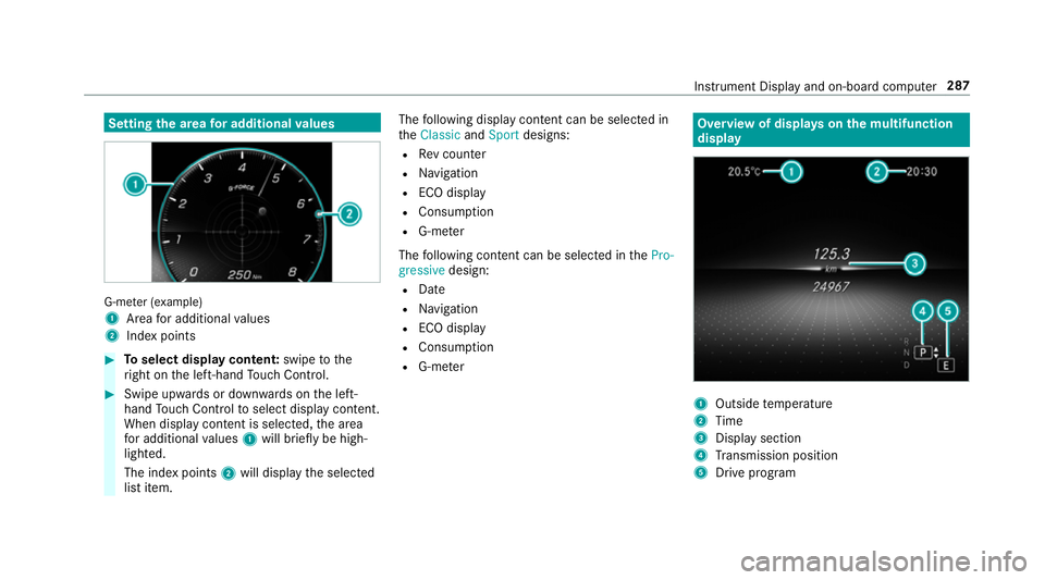
the area for additional values G-me
ter (e xamp le)
1 Area for additional values
2 Indexpoints #
Toselect display content: swipetothe
ri ght on the left-hand Touch Control. #
Swipe upwards or down wards on the left-
hand Touch Control toselect display content.
When display content is selected, the area
fo r additional values 1will briefly be high‐
lighted.
The index points 2will display the selected
list item. The
following display con tent can be selected in
th eClassic andSport designs:
R Rev counter
R Navigation
R ECO display
R Consu mption
R G-m eter
The following con tent can be selected in thePro-
gressive design:
R Date
R Navigation
R ECO display
R Consu mption
R G-m eter Overview of displa
yson the multifunction
display 1
Outside temp erature
2 Time
3 Display section
4 Transmission position
5 Drive prog ram Instrument Display and on-board computer
287