2019 MERCEDES-BENZ GLB SUV change wheel
[x] Cancel search: change wheelPage 537 of 689
Re
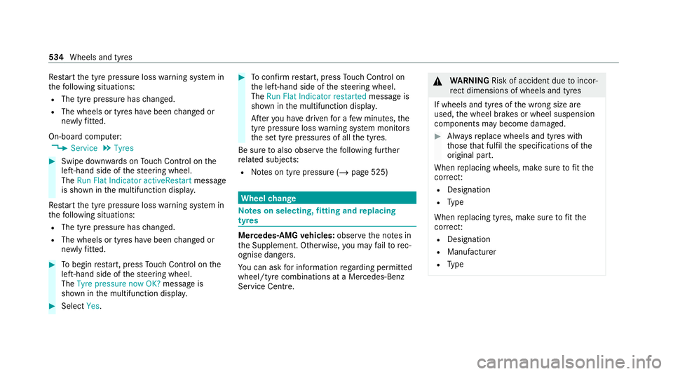
start the tyre pressure loss warning sy stem in
th efo llowing situations:
R The tyre pressure has changed.
R The wheels or tyres ha vebeen changed or
newly fitted.
On-boa rdcompu ter:
4 Service 5
Tyres #
Swipe down wards on Touch Control on the
left-hand side of thesteering wheel.
The Run Flat Indicator activeRestart message
is shown in the multifunction displa y.
Re start the tyre pressure loss warning sy stem in
th efo llowing situations:
R The tyre pressure has changed.
R The wheels or tyres ha vebeen changed or
newly fitted. #
Tobegin restart, press Touch Control on the
left-hand side of thesteering wheel.
The Tyre pressure now OK? message is
shown in the multifunction displa y.#
Select Yes. #
Toconfirm restart, press Touch Control on
th e left-hand side of thesteering wheel.
The Run Flat Indicator restarted message is
shown in the multifunction displa y.
Af teryo u ha vedriven for a few minutes, the
tyre pressu reloss warning sy stem monitors
th e set tyre pressures of all the tyres.
Be sure toalso obse rveth efo llowing fur ther
re lated subjects:
R Notes on tyre pressure (/ page 525) Wheel
change Note
s on selecting, fitting and replacing
tyres Mercedes
-AMG vehicles: observeth e no tes in
th e Supplement. Otherwise, you may failto rec‐
ognise dangers.
Yo u can ask for information rega rding permit ted
wheel/tyre combinations at a Mercedes-Benz
Service Cent re. &
WARNING Risk of accident due toincor‐
re ct dimensions of wheels and tyres
If wheels and tyres of the wrong size are
used, the wheel brakes or wheel suspension
components may become damaged. #
Alw aysre place wheels and tyres with
th ose that fulfil the specifications of the
original part.
When replacing wheels, make sure tofit the
cor rect:
R Designation
R Type
When replacing tyres, make sure tofit the
cor rect:
R Designation
R Manufactu rer
R Type 534
Wheels and tyres
Page 539 of 689
*
NO
TEDama getoelectronic component
parts from the use of tyre-fitting tools Ve
hicles with a tyre pressure monitoring
sy stem: electronic component parts are
located in the wheel. Tyre-fitting tools should
not be applied in the area of theva lve.
The tools could damage the electronic com‐
ponent parts. #
Have the tyres changed at a qualified
specialist workshop onl y. *
NO
TEDama getosummer tyres at low
ambient temp eratures At
low ambient temp eratures, tears could
fo rm when driving with summer tyres, caus‐
ing permanent damage tothe tyre. #
Attemp eratures below 7 °C, use M+S
tyres. Ac
cessory pa rts th at are not appr ovedfo ryo ur
ve hicle byMercedes-Benz or are not being used
cor rectly can impair the operating saf ety. Before pu
rchasing and using non-appr oved
accesso ries, visit a qualified specialist workshop
and enquire about:
R Suitability
R Legal stipulations
R Factory recommendations &
WARNING Risk of accident wi thhigh
per form ance tyres
The special tyre tread in combination with
th e optimised tyre compound, means that
th erisk of skidding or hydroplaning on wet
ro ads is inc reased.
In addition, the tyre grip is greatly reduced at
a low outside temp erature and tyre running
te mp erature. #
Switch on the ESP ®
and adapt your
driving style accordingly. #
Use M+S tyres at outside temp eratures
of less than 50 °F. Obse
rveth efo llowing when selecting, fitting and
re placing tyres:
R Countr y-specific requirements for tyre
appro valth at define a specific tyre type for
yo ur vehicle.
Fu rthermore, the use of cer tain tyre types in
cer tain regions and areas of operation can
be highly beneficial.
R Only use tyres and wheels of the same type
(summer tyres, winter tyres, MOEx tended
tyres) and the same make.
R Only fit wheels of the same size on one axle
(left and right).
It is only permissible tofit a di fferent wheel
size in theeve nt of a flat tyre in order to
drive tothe specialist workshop.
R Only fit tyres of the cor rect size onto the
wheels.
R Do not make any modifications tothe brake
sy stem, the wheels or the tyres.
The use of shims or brake dust shields is not
permitted and may in validate theve hicle's
ge neral operating pe rmit. 536
Wheels and tyres
Page 541 of 689

Do not drive wi
thtyres that ha vetoo little tread
dep th. This significantly reduces traction on wet
ro ads (aquaplaning).
On vehicles with the same front and rear wheel
size, you can inter change the wheels every
5,000 to10,000 km, depending on thewe ar.
Ensure the direction of rotation is maintained for
th e wheels.
Obser vethe instructions and saf ety no tes on
"Changing a wheel" when doing so
(/ page 539). Note
s onstoring wheels When
storing wheels, obser vethefo llowing
no tes:
R Afterre moving wheels, store them in a cool,
dry and preferably dark place.
R Protect the tyres from conta ct withoil,
grease or fuel. Overview of
the ty re-change tool kit Apart from some countr
y-specific variants, vehi‐
cles are not equipped with a tyre-change tool kit.
Fo r more information on which tyre-changing
to ol kits are required and appr oved for per form‐
ing a wheel change on your vehicle, consult a
qu alified specialist workshop.
Yo ure qu ire thefo llowing tools, for ins tance, to
ch ange a wheel:
R Jack
R Chock
R Wheel wrench
R Cent ring pin
% The jack weighs appr oximately 3.4 kg.
The maximum load capacity of the jack can
be found on thest icke r af fixe dto the jac k.
The jack is maintenance-free. If there is a
malfunction, please conta ct aqualified spe‐
cialist workshop.
The tyre-change tool kit is located in tool bag 1
in the load compartment. To
ol bag contains:
R Jack
R Gloves
R Wheel wrench
R Centring pin
R Folding chock
R Ratchet for jack 538
Wheels and tyres
Page 542 of 689
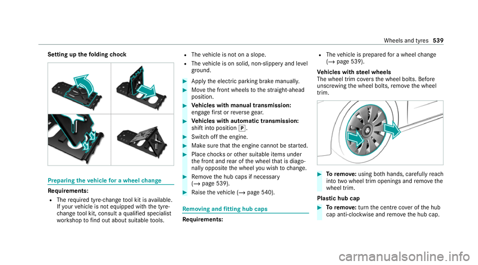
Setting up
thefo lding chock Prepa
ring theve hicle for a wheel change Re
quirements:
R The requ ired tyre-change tool kit is available.
If yo ur vehicle is not equipped with the tyre-
ch ange tool kit, consult a qualified specialist
wo rkshop tofind out about suitable tools. R
The vehicle is not on a slope.
R The vehicle is on solid, non-slippery and le vel
ground. #
Apply the electric parking brake manually. #
Movethe front wheels tothest ra ight-ahead
position. #
Vehicles with manual transmission:
engage firs t or reve rsege ar. #
Vehicles with automatic transmission:
shift into position j. #
Switch off the engine. #
Make sure that the engine cann otbe star ted. #
Place choc ks orother suitable items under
th e front and rear of the wheel that is diago‐
nally opposite the wheel you wish tochange. #
Remo vethe hub caps if necessary
(/ page 539). #
Raise theve hicle (/ page540). Re
moving and fitting hub caps Re
quirements: R
The vehicle is prepared for a wheel change
(/ page 539).
Ve hicles with steel wheels
The wheel trim co vers the wheel bolts. Before
unscr ewing the wheel bolts, remo vethe wheel
trim. #
Toremo ve:using bo thhands, carefully reach
into two wheel trim openings and remo vethe
wheel trim.
Plastic hub cap #
Toremo ve:turn the cent recover of the hub
cap anti-clockwise and remo vethe hub cap. Wheels and tyres
539
Page 543 of 689
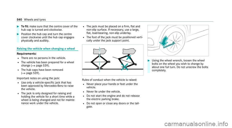
#
Tofit: make sure that the cent recover of the
hub cap is turned anti-clockwise. #
Position the hub cap and turn the cent re
co ver clockwise until the hub cap engages
ph ysically and audibly. Ra
ising theve hicle when changing a wheel Re
quirements:
R There are no persons in theve hicle.
R The vehicle has been prepared for a wheel
ch ange (/ page 539).
R The hub caps ha vebeen remo ved
( / page 539).
Impor tant no tes on using the jack:
R Use only a vehicle-specific jack that has
been appr oved byMercedes-Benz toraise
th eve hicle.
R The jack is only designed forra ising and
holding theve hicle for a short time while a
wheel is being changed and not for mainte‐
nance workunder theve hicle. R
The jack must be placed on a firm ,fl at and
non-slip sur face. If necessar y,use a lar ge,
fl at, load-bearing, non-slip unde rlay.
R The foot ofthe jack must be positioned verti‐
cally under the jack support point. Ru
les of conduct when theve hicle is raised:
R Never place your hands or feet under the
ve hicle.
R Never lie under theve hicle.
R Do not start the engine and do not release
th e electric parking brake.
R Do not open or close any doors or theta il‐
gate. #
Using the wheel wrench, loosen the wheel
bolts on the wheel you wish tochange by
about one full turn. Do not unscr ewthe bolts
comple tely. 540
Wheels and tyres
Page 544 of 689
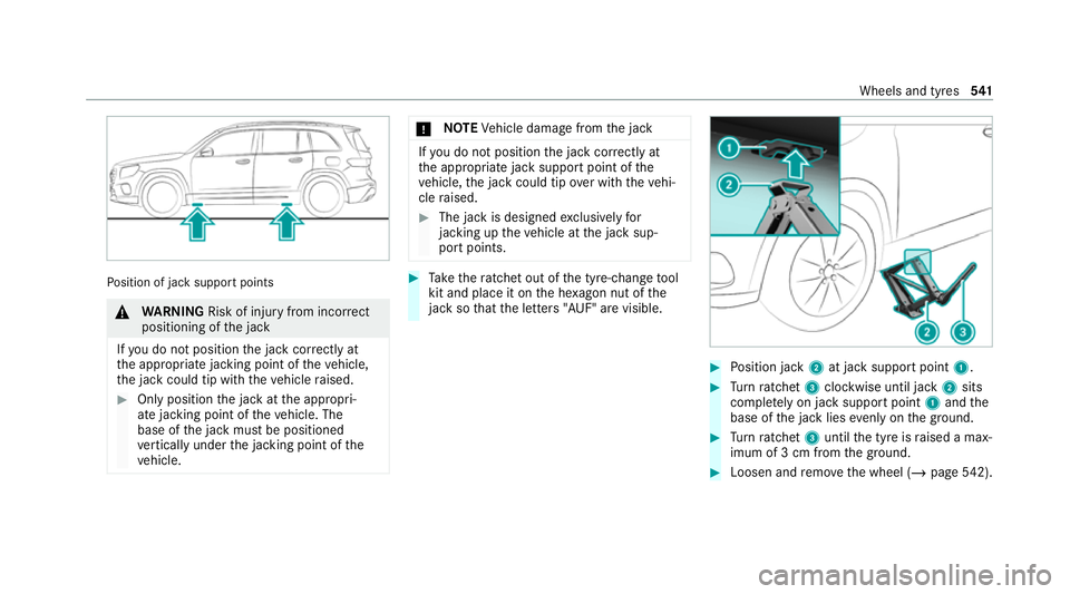
Po
sition of jack support points &
WARNING Risk of inju ryfrom incor rect
positioning of the jack
If yo u do not position the jack cor rectly at
th e appropriate jacking point of theve hicle,
th e jack could tip with theve hicle raised. #
Only position the jack at the appropri‐
ate jacking point of theve hicle. The
base of the jack must be positioned
ve rtically under the jacking point of the
ve hicle. *
NO
TEVehicle damage from the jack If
yo u do not position the jack cor rectly at
th e appropriate jack support point of the
ve hicle, the jack could tip over with theve hi‐
cle raised. #
The jack is designed exclusively for
jacking up theve hicle at the jack sup‐
port points. #
Take thera tchet out of the tyre-change tool
kit and place it on the he xagon nut of the
jack so that the letters "AUF" are visible. #
Position jack 2at jack support point 1. #
Turn ratchet 3clockwise until jack 2sits
comple tely on jack support point 1and the
base of the jack lies evenly on the ground. #
Turn ratchet 3until the tyre is raised a max‐
imum of 3 cm from the ground. #
Loosen and remo vethe wheel (/ page542). Wheels and tyres
541
Page 546 of 689
#
Slide the wheel tobe mounted onto the cen‐
tring pin and push it on. #
Notes on fitting an eme rgency spare wheel
(/ page 544). &
WARNING Risk of inju ryfrom tightening
wheel bolts and nuts
If yo u tighten the wheel bolts or wheel nuts
when theve hicle is raised, the jack could tip. #
Only tighten wheel bolts or wheel nuts
when theve hicle is on the ground. #
Be sure toobser vethe instructions and
saf ety no tes on "Changing a wheel"
(/ page 534). #
For saf etyre asons, on lyuse wheel bolts
which ha vebeen appr ovedby Mercedes-
Benz and forth e wheel in question. #
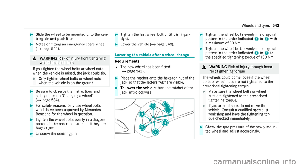
Tighten the wheel bolts evenly in a diagonal
pattern in the order indicated until they are
fi nger-tight. #
Unscr ew the cent ring pin. #
Tighten the last wheel bolt until it is finger-
tight. #
Lowe rth eve hicle (/ page543). Lo
weri ngtheve hicle af ter a wheel change Re
quirements:
R The new wheel has been fitted
(/ page 542). #
Place thera tchet onto the he xagon nut of the
jack so that the letters "AB" are visible. #
Tolowe r the vehicle: turnthera tchet of the
jack anti-clo ckwise. #
Tighten the wheel bolts evenly in a diagonal
pattern in the order indicated 1to5 with
a maximum of 80 Nm. #
Tighten the wheel bolts evenly in a diagonal
pattern in the order indicated 1to5 to
th e specified tightening torque of 130 Nm. &
WARNING Risk of inju rythro ugh incor‐
re ct tigh tening torque
The wheels could come loose if the wheel
bolts or wheel nuts are not tightened tothe
prescribed tightening torque. #
Makesure the wheel bolts or wheel
nuts are tightened tothe prescribed
tightening torque. #
Ifyo u are not sure, do not mo vethe
ve hicle. Consult a qualified specialist
wo rkshop and ha vethe tightening tor‐
qu ech ecked immediately. #
Check the tyre pressure of the newly moun‐
te d wheel and adjust according ly. Wheels and tyres
543
Page 642 of 689
1,
2, 3 ...
4MATIC ..................................................... 208
Fu nction .............................................. 208
12 V battery
see Battery (vehicle)
12 V so cket
see Soc ket (12 V)
11 5 V soc ket
see Soc ket (1 15 V)
230 V soc ket
see Soc ket (230 V)
360° Camera ........................................... 267
Ca re .................................................... 497
Fu nction .............................................. 267
Opening the camera co ver (r eve rsing
camera) .............................................. .270
Selecting a view .................................. 270
Switching au tomatic operation
on/off (r eversing camera) .................. .270 A
A/C function Activating/deactivating (multimedia
sy stem) ................................................ 17 7
Switching on/off (control panel) .......... 176
ABS (Anti-lock Braking Sy stem) ............ .226
Ac celeration
see Kickdown
Ac cess data
Setting (Blue tooth®
) ............................ 460
Ac cident and breakdown manage‐
ment
Mercedes me connect ........................ .450
Ac oustic locking verification signal
Ac tivating/deactivating ......................... 83
Ac tivating/deactivating automatic
vo lume adjustment
Burmes ter®
sur round sound sy stem ....4 81
Ac tive Blind Spot Assi st......................... 282
Ac tivating/deactivating ...................... .285
Brake application ................................. 284
Fu nction .............................................. 282
Sy stem limitations ...............................2 82Tr
ailer operation .................................. 284
Ac tive bonn et(pedestrian pr otection) .. 485
Operation ............................................ 485
Re setting ............................................. 485
Ac tive Brake Assi st
Fu nction/no tes ................................... 231
Setting .................................................2 37
Ac tive Di stance Assist DISTRO NIC........ 24 3
Ac tive Emergency Stop Assist .............2 53
Ac tive Lane Change Assi st................... 251
Calling up a speed ............................... 24 5
Displ ays in the instrument display .......2 53
Fu nction .............................................. 24 3
Increasing/decreasing speed .............. 24 5
Re quirements: .................................... .245
Ro ute-based speed adap tation ........... .247
Selecting ............................................. 24 5
St eering wheel buttons ........................ 24 5
St oring a speed ................................... 24 5
Switching off/deacti vating .................. 24 5
Switching on/activating ...................... 24 5
Sy stem limitations ...............................2 43
Ac tive Eme rgency Stop Assist ...............253
Ac tive headlamps .................................... 15 8 Index
639