2019 MERCEDES-BENZ G-CLASS trailer
[x] Cancel search: trailerPage 191 of 514
#
Beprepa redto brak eor sw erve as nec ‐
essar y,prov ided thetra ffic situat ion
per mitsand that itis saf eto take eva‐
siv eact ion. Dr
ive Aw ayAssi stisonl yan aid. Itis no ta sub‐
st itut efo ryo ur att entio nto thesur round ings.
The responsibili tyforsaf emaneu vering and
pa rking remains withyo u. Mak esur eth at no
per son s,anim alsorobj ect set c. arein the
maneu vering rang e.
A risk ofacollision mayar ise inthefo llo wing sit‐
uation s,forex am ple:
R Ifth edr iver mix esup theaccelera torand
br ak epeda ls.
R Ifth ewr ong gear isselec ted.
The Drive Aw ayAssi stfunction isactiv eunder
th efo llo wing condition s:
R IfPa rking AssistPA RK TRONI Cis act ivat ed.
R Everytime thege ar isch ang edto005E or005B
when theve hicle isat ast ands till.
R Ifth ede tected obs tacle isless than appr ox.
3.3 ft(1.0 m) away. R
Ifth emaneuv ering assis tance func tionis
acti vatedin themultimedia system.
Sy stem limita tions
Dr ive Aw ayAssi stisno tav ailable onincline sand
when drivin gwit hatrailer .
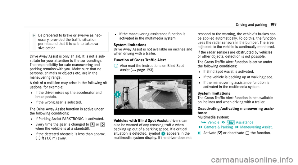
Fu nction ofCross Traf fic Aler t
% Alsore ad theins truction son Blind Spot
Assis t(/ page19 3). Ve
hicl eswith Blind SpotAss ist: driver scan
also bewarned ofanycr ossing traf fic whe n
ba cking upout ofapar kingspace. Ifacr itic al
situat ionisde tected, symbo l1 appea rsinthe
multime diasystem displa y.Ifth edr iver does not re
spond tothewa rning, theve hicle's brak es can
be appli edaut omaticall y.To do this, thefunc tion
uses thera dar sensor sin thebum per.The area
adjacen tto theve hicle iscont inually monitored.
If th era dar sensor sar eobs truct edbyvehicles
or other object s,de tection isno tpos sible.
The Cross Traf fic Aler tfuncti onisacti veund er
th efo llo wing condition s:
R IfBlin dSpo tAss istis act ivat ed.
R Ifth eve hicle isbac king upatwa lkin gpace.
R Ifth emaneuv ering assis tance func tionis
acti vatedin themultimedia system.
Sy stem limita tions
The Cross Traf fic Aler tfuncti onisno tav ailable
on incline sand when drivin gwit hatrailer .
Deact ivat ing/a ctivating maneuv ering assis‐
tance
Mult imed iasystem:
4 Vehicle 5
k Assist ance
5 Camera &Parkin g5
Maneuverin gAssist . #
Activate0073 ordeacti vate 0053 thefunc tion. Dr
iving andparking 18
9
Page 200 of 514
Ve
hicl eswithout Parking Assis t
PA RK TRONI C: #
Activate/d eactiv ateAc tiveLa ne Keeping
Assis tvia themultimedia system
(/ page19 8).
Se nsitiv ity of Activ eLan eKe eping Assist
Wi th theSt andar dor Adaptivese tting ,yo ucan
inf luen cewhen thewa rning vibra tionofLane
Ke eping Assisttak esplace.
In both theSt andar dand Adaptivese tting s,no
wa rning vibra tionoccursin thefo llo wing situa‐
tion s:
R Youha ve switc hedonthetur nsignal indica‐
to r.
R Adr ivi ng safety system interve nes, such as
AB S,BA Sor ESP ®
.
In theAd aptivese tting ,th er ewill also beno
wa rning vibra tioninthefo llo wing situat ions:
R The vehicle isacceler ated orbrak ed consid‐
er abl y.
R Yousteer activ ely, e.g. swerve toavo idan
obs tacle orchang elane quickl y. R
Youcut thecor ner onashar pbend.
Se tting thesensit ivityof Activ eLan eKe ep‐
ing Assis t
Multi media system:
4 Vehicle 5
k Assist ance
5 Act .Lane Keep. Assist #
Select Adaptive orStandard.
Ac tiveLa ne Keeping Assistis activ ated with
th eselect edsetting.
or #
Select Off.
Ac tiveLa ne Keeping Assistis deactiv ated. Tr
aile rhitc h No
teson towing atrail er Mer
cede s‑AMG vehicl es:alwaysobser vethe
no tesin theSupplement .Ot her wise, youma y
no tre cogni zedangers. Obs
erve thefo llo wing noteson theto ngu e
we ight :
R Donotuse ato ngu ewe ight that exceed sor
fa lls belo wtheper missible tongu ewe ight
R Use ato ngu ewe ight asclos eas possible to
th emaximum tongu ewe ight
Do notex ceed thefo llo wing values:
R Perm issible towing capac ity
R Perm issible rear axle load oftheto wing vehi‐
cle
R Perm issible gross mass oftheto wing vehicle
R Perm issible gross mass ofthetra iler
R Maximum permissible speedofthetra iler
En sur eth efo llo wing beforest ar tin gajo ur ne y:
R The tirepr essur eon there ar axle oftheto w‐
ing vehicle issetfo ra maximu mloa d
R The lighting ofthecon nect edtrailer isoper a‐
tion al
R Vehicl eswithout LEDheadlam psorMUL‐
TIBEA MLED headlam ps:theheadlam ps
ha ve been setcor rectl y 19
8
Driving and parking
Page 201 of 514

In
theeve ntofincr eased rear axle load, theve hi‐
cle/tra ilercombination mayno texc eed amaxi‐
mum speed of62 mph(1 00 km/h) forre ason s
con cerningth eoper ating permit. This also
applies incount ries inwhic hth eper missible
maximum speedforve hicle/tr ailercombinations
is abo ve62 mph(1 00 km/h). Coupling
up/uncoupling atrailer Re
quirement s:
Tr ailer swit ha7- pin plug canbecon nectedto
th eve hicle withth efo llo wing adapters:
R Adapterplu g
R Adaptercabl e
The trail er wil lbe cor rectly detected bytheve hi‐
cle onlyif th efo llo wing condition sar eme t:
R The trailer isconn ectedcor rectly
R The trai le rlighti ngsystem isin wo rking order
The func tionsof thefo llo wing systems areaf fec‐
te dby acor rectly connect edtrai le r:
R ActiveLa ne Keeping Assist R
ESP®
tra iler stabiliz ation
R Parking AssistPA RK TRONI C
R ActivePa rking Assist
R Blin dSpo tAss ist
Couplin gup atrailer
* NO
TEDama getotheve hicle batterydue
to full disc harge Char
gingth etra iler batt eryusing thepo we r
supply ofthetra iler can damag eth eve hicle
batt ery. #
Donotus eth eve hicle's powe rsupp ly
to charge thetrailer battery. Inf
ormation abouta suit ablebal lhead for
Mer cedes-Ben zve hicles canbeobt ained from a
qu alif ied spec ialistwo rkshop, e.g.anaut hor ized
Mer cedes-Benz Center. #
Position thetra iler onaleve lsur face beh ind
th eve hicle andcouple itup totheve hicle. #
Open thesoc ketcap . #
Inse rttheplug withlug 1ingroo ve 3 on
th esoc ket. #
Turn theba yone tcou pling 2clockwise as
fa ras itwil lgo. #
Letth ecap engage. #
Secur eth ecable tothetrailer withcable ties
(onl yif yo uar eusin gan adap tercabl e). #
Mak esur eth at thecable isalw aysslac kfo r
ease ofmo vement during corner ing. Dr
iving andparking 19
9
Page 202 of 514
A
displ aymessa gema yapp ear onthemultifunc ‐
tion displa yeve nif th etra iler has been connec‐
te dcor rectl y:
R LEDs have been installed inthetra iler light‐
ing system
R The current hasfa llen belo wthetrailer light‐
ing system's minimum current (50 mA).
% Access oriescan beconnect edtotheper ma‐
nen tpo we rsupp lyup to180W, and tothe
po we rsupp lythat isswit ched on via theigni‐
tion lock.
Decoup lingatrail er &
WARNIN GRisk ofbei ng crus hed and
beco ming trap ped whenunco upling a
tr ai le r
Whe nunco upling atrai le rwi th an eng aged
ine rtia-act ivat ed brak e, your han dma y
bec ome trapped between theve hicle andthe
tr ai le rdr aw bar . #
Donotuncouple trailer swit han
eng aged ove rrunbr ak e. #
Secu rethetrailer agains tro lling away. #
Disconne cttheelectr icalconnect ion
be tween theve hicle andthetra iler . #
Uncou ple th etra iler . #
Place theco veron theball head. Ve
hicl eto wing instruct ions
The vehicle isno tsuit able forth euse oftow bar
sy stems that areused forflat towing ording hy
to wing, forex am ple. Attach ing and using tow bar
sy stems canlead todamag eon theve hicle.
When youar eto wing ave hicle withto w bar sys‐
te ms, safedr iving charact eristic scan notbe
guar anteed forth eto wing vehicle ortheto we d
ve hicle. Thevehicle-tr ailercombination may
sw erve from side toside. Complywithth eper‐
mitt edtowing methods (/page362) andthe
ins truct ions forto wing withbo th axle son the
gr ou nd (/ page 363). 200
Driving andparking
Page 367 of 514
Obser
vethefo llo wing during reco very to avo id
damag eto your vehicle:
R Ifth edr iven wheels gettr ap pe don loose or
mu ddygr ou nd, reco verth eve hicle withth e
utm ostcar e,
Es pec iallyso ifth eve hicle isladen.
R Neveratt em pttoreco vera ve hicle that is
st uc kwit hatrailer attached.
R Pull outtheve hicle that isstuc kbac kwards,
if poss ible, usingth etra cksit made beforeit
became stuc k. To
wing vehicl eaw ay intheeve ntofmalf unc‐
tions No
teson towing away intheev ent ofma l‐
fun ctions
* NO
TEDama gedue toinc orrect att ach‐
ment anduseof old nuts The
vehicle andcomponent sof theve hicle
can bedamag eddue toinc orrect att achment
and useof old nuts. #
Ifyo ure mo vethepr opeller shaft,place
th eM1 0nuts ontheM8 bolts as
spacer sand secur eth em withM8 nuts. #
Alw aysuse newself-loc kingnuts when
ins talling thepr opeller shafts. Obser
vetheno teson towing away
( / pag e362).
% Forfur ther information ,con sult anaut hor‐
ized Mercedes- BenzCenter.
To wing away intheev ent ofma lfun ctions
To wing away intheev ent ofdama getothe
engine, transm ission orelectr ics #
Shif tth etra nsmiss iontoposition 005C.
To wing away intheev ent oftransf ercase
da ma ge #
Remo vethepr opeller shaftsbetween the
axle sand thetransf ercase. To
wing away intheev ent offront axle dam‐
ag e #
Remo vethepr opeller shaftbe tween there ar
axle andthetransf ercase. #
Tow aw ay theve hicle withara ised front axle.
To wing away intheev ent ofrear axle dam‐
ag e #
Remo vethepr opeller shaftbe tween thefront
axle andthetransf ercase. #
Tow aw ay theve hicle withara ised rear axle
and withwheel roller sunder thefront axle. Loading
theve hicl efo rtr ans port #
Obser vetheno teson towing away
( / pag e362). #
Connec tth eto w bar totheto wing eyein
or der toload theve hicle. #
Shif tth etra nsmiss iontoposition 005C. Br
eakdo wnassis tance 36
5
Page 389 of 514

Un
ifor m Tire Quality Grading Standar ds:a
unif orm standar dto grade thequ alit yof tires
wit hre ga rd totrea dqu alit y,tiretracti onand
te mp eratur ech aract eristic s.The qualit ygr adin g
asses smentismade bythemanuf acturerfollo w‐
ing spec ificat ions from theU. S. government. The
qu alit ygr ade ofatir eis im print ed on theside
wa llof thetir e.
Re comm endedtir epr essu re:th ere comme n‐
ded tirepr ess ureis thetir epr essur especif ied
fo rth etir es mount edtotheve hicle atthefa c‐
to ry.
The tireand information table con tains there c‐
omme ndedtirepr ess ures forcold tires, themax‐
imum permissible loadandthemaximum per‐
missible vehicle speed.
The tirepr essur eta ble con tains there comme n‐
ded tirepr ess ures forcold tires under various
oper ating condit ions,i.e.loading and/orspeed
of theve hicle.
Incr eased vehicl ewe ight duetooptiona l
eq uip ment :th ecombin edweight ofall standar d
and optio nal equipme ntavailable forth eve hicle, re
ga rdless ofwhe ther itis actually installed on
th eve hicle ornot.
Rim: thepar tof thewheel onwhic hth etir eis
ins talled.
GA WR (Gross AxleWe ight Ratin g):th eGA WR
is themaximum permissible axleload. The
actual loadonanaxle mustne verexc eed the
gr os saxle weight rating .The gross axlewe ight
ra ting canbefound ontheve hicle identif ication
plat eon theB‑pillar onthedr iver's side.
Speed ratin g:thespeed rating ispa rtof thetir e
identif ication .It specif iesthespeed rang efo r
whic hatir eis appr oved.
GV W(Gr oss Vehicl eWe ight ):th egr oss vehicle
we ight comprises thewe ight oftheve hicle
including fuel,tools, thespar ewheel, accesso‐
ri es installed, occupant s,lugg ageand thetrailer
dr aw bar nose weight ,if applicable. Thegros s
ve hicle weight mustno texc eed thegr oss vehicle
we ight rating GVWR asspecif iedontheve hicle
identif ication plateon theB‑pillar onthedr iver's
side.
GV WR (Gross Vehicl eWe ight Ratin g):th e
GV WR isthemaximum permitt edgross weight of
thefully laden vehicle (weight oftheve hicle
including allaccessor ies,occupants, fuel,lug‐
ga ge and thetrailer draw bar nose weight ifappli‐
cable). Thegros sve hicle weight rating issp eci ‐
fi ed on theve hicle identif ication plateon the
B‑pil laron thedr iver's side.
Maxim umweight ofthelad envehicl e:the
maximu mwe ight isthesum ofthecurb weight
of theve hicle, thewe ight oftheaccesso ries, the
maximu mloa dand thewe ight ofoption aleq uip‐
men tins talled atthefa ct or y.
Kilop ascal(kP a):metric unit fortir epr essu re.
6.9 kPacor responds to1psi .Ano ther unit for
tir epr es su re isbar .10 0kilop ascal(kP a)equals
1 bar .
Lo ad inde x:inadd ition totheload-bear ing
inde x,theload indexma yalso beimprint ed on
th eside wallof thetir e. This specif iestheload-
bear ingcapacity ofthetir emor epr ecisel y.
Cur bwe ight :th ewe ight ofave hicle withstand‐
ar deq uipme ntinc ludin gth emaximum capacity
of fuel, oiland coolant .It also includes theair
con ditionin gsy stem and option aleq uipment if Wheels
andtires 38
7
Page 413 of 514
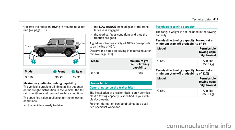
Obser
vetheno teson driving inmount ainous ter‐
ra in (/ page13 1). Mo
del
1 1
Front 2 2
Rear
G 550 30.9°29.9° Maximum
gradien t-climbing capability
The vehicle's gradient climbing abilitydepends
on thewe ight distribution intheve hicle, thete r‐
ra in con dition sand thero ad sur face condi tions.
The specified va lue applies underthefo llo wing
con dition s:
R theve hicle isready todrive R
theLOW RANGEoff-r oa dge ar ofthetrans‐
fe rcase iseng aged
R thero ad sur faces condi tions andthus the
tr acti onarego od
A grad ient climbi ngability of100% corresponds
to an incline of45 °.
Obse rveth eno teson driving inmount ainous ter‐
ra in (/ page13 1). Mo
del Maximum gra‐
dien t-climbing
capabi lity
G 550 100% Tr
aile rhitc h Gene
ralno teson thetrailer hitch The
installation ofatrailer hitchis onl yper missi‐
ble ifato wing capac ityisspec ified inyour vehi‐
cle documents.
Fu rther information canbeobt ained ataqu ali‐
fi ed specialis two rkshop. Pe
rm issible towing capacit y The
tongu ewe ight isno tinc luded intheto wing
capac ity.
Pe rm issible towing capacit y,brak ed (at a
minim umstar t-of fgr adeabi lityof8%) Model
Perm issible
to wing capa‐
cit y,brak ed
G 550 7716 lbs
(350 0kg ) Pe
rm issible towing capacit y,brak ed (at a
minim umstar t-of fgr adeabi lityof12%) Model
Perm issible
to wing capa‐
cit y,brak ed
G 550 7716 lbs
(350 0kg ) Te
ch nica lda ta 41
1
Page 414 of 514
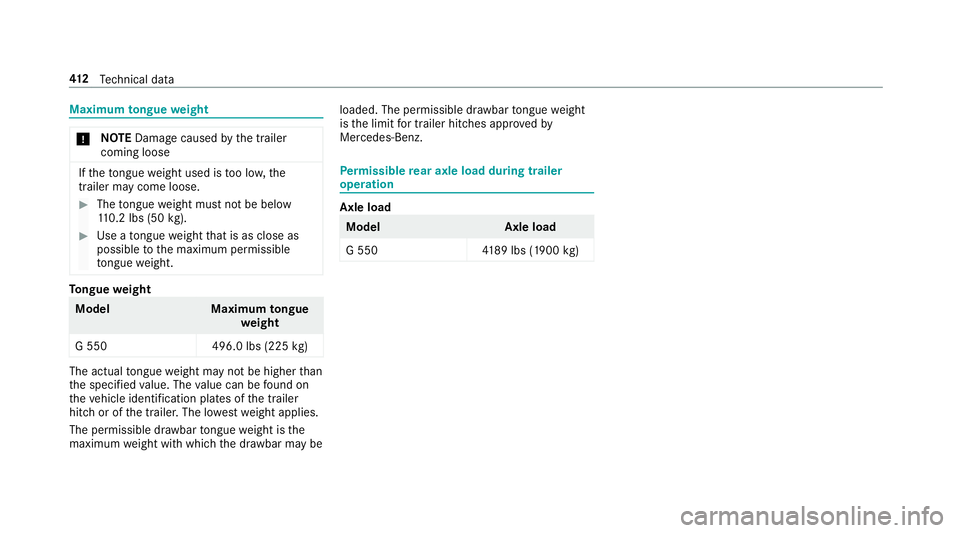
Maximum
tongue weight *
NO
TEDama gecau sed bythetrailer
comin gloose If
th eto ngu ewe ight used istoolow, the
tr ai le rma ycome loose . #
The tongu ewe ight mustno tbe belo w
11 0.2 lbs(50 kg). #
Use ato ngu ewe ight that isas clo seas
poss ibletothemaximum permissible
to ngu ewe ight . To
ngue weight Model
Maximumtongue
we ight
G 550 496.0lbs (225 kg) The
actual tongu ewe ight mayno tbe higher than
th especif iedvalue. Thevalue can befound on
th eve hicle identif ication platesofthetrailer
hitc hor ofthetra iler .The lowe stwe ight applies.
The permissib ledraw bar tongu ewe ight isthe
maximu mwe ight withwhic hth edr aw bar maybe loaded.
Thepermissible draw bar tongu ewe ight
is thelimit fortr ail er hitc hes approve dby
Mer cedes-Ben z. Pe
rm issible rear axle load during traile r
oper ation Axl
eload Model
Axleload
G 550 4189 lbs (1900 kg) 41
2
Tech nica lda ta