2019 MERCEDES-BENZ CLA COUPE tow
[x] Cancel search: towPage 508 of 645
at
the nearest qualified specialist work‐
shop. The new wheel must ha vethe
cor rect dimensions. Check
the tyre pressure of the emer gency spa re
wheel fitted. Co rrect the pressure as necessar y.
The maximum permissible speed with an emer‐
ge ncy spa rewheel fitted is 80 km/h.
Do not fit th e emer gency spa rewheel with sn ow
ch ains.
Re place the emer gency spa rewheel af ter six
ye ars at the latest, rega rdless of wear.
% Ve
hicles with a tyre pressure loss warn‐
ing sy stem: if an emer gency spa rewheel is
fi tted the tyre pressure loss warning sy stem
cann otfunction reliabl y.Only restart the sys‐
te m again when the emer gency spa rewheel
has been replaced with a new wheel.
Ve hicles with a tyre pressure monitoring
sy stem: if an emer gency spa rewheel is fit‐
te dth e tyre pressure monitoring sy stem can‐
not function reliabl y.Fo r a few minutes af ter
an emer gency spa rewheel is fitted, the sys‐
te m may still display the tyre pressure of there
mo ved wheel. Only restart the sy stem
again when the emer gency spa rewheel has
been replaced with a new wheel.
Be sure toalso obse rveth efo llowing fur ther
re lated subjects:
R Notes on tyre pressure (/ page 486)
R Tyre pressure table (/ page 487) Re
moving the eme rgency spa rewheel The deflated eme
rgency spare wheel is secured
in the emer gency spa rewheel bag in the boot. #
Obser vethe information on mounting tyres
(/ page 495). #
Open the boot. #
Detach thefast ening stra ps. #
Unhook there taining spring hooks of thefa s‐
te ning stra ps from the brac kets. #
Remo vethe emer gency spa rewheel bag with
th e emer gency spa rewheel. #
Open the emer gency spa rewheel bag and
re mo vethe emer gency spa rewheel. Inflating
the emer gency spare wheel *
NO
TEOverheating due tothe tyre infla‐
tion compressor running too long #
Do not runth e tyre inflation compres‐
sor for longer than ten minu tes without
inter ruption. Re
quirements:
R Comply with the manufacturer's saf ety no tes
on thest icke r of the emer gency spa rewheel
and on the tyre inflation compressor.
R Remo vethe tyre inflation compressor from
th estow age space under the boot floor
(/ page 466). Wheels and tyres
505
Page 510 of 645
#
Stow filling hose 2and plug 4inthe lo wer
section of the compressor housing. #
Stow th e tyre inflation compressor in the
ve hicle. Collapsible spare wheel
Note
s onthe collapsible spa rewheel &
WARNING Risk of accident caused by
incor rect wheel and tyre dimensions
The wheel or tyre size and the tyre type of
th e emer gency spa rewheel or spare wheel
and the wheel tobe replaced may dif fer.
Mounting an emer gency spa rewheel/spare
wheel may se verely impair the driving char‐
acteristics.
To preve nt hazardous situations: #
Adapt your driving style according lyand
drive carefull y. #
Neverfit more than one emer gency
spa rewheel or spare wheel that dif fers
in size. #
Only use an emer gency spa rewheel or
spare wheel of a dif fere nt size brie fly. #
Do not switch off ESP ®
. #
Have the emer gency spa rewheel or
spare wheel of a dif fere nt size replaced
at the nearest qualified specialist work‐
shop. The new wheel must ha vethe
cor rect dimensions. The collapsible spa
rewheel is an emer gency
wheel which is only suitable for use for a limi ted
period of time and in a restricted manner in the
eve nt of a flat tyre (e.g. until the nearest work‐
shop).
The tyre side walls are folded when in transpo rt
mode. Before use, the collapsible spare wheel
has tobe inflated with the accompanying com‐
pressor.
Check the tyre pressure of the collapsible spare
wheel once fitted. Co rrect the pressure as nec‐
essar y.
The maximum permissible speed with a collapsi‐
ble spare wheel fitted is 80 km/h. Do not
fit snow chains with the collapsible spare
wheel.
Re place the collapsible spare wheel af ter six
ye ars at the latest, rega rdless of wear.
% Ve
hicles with a tyre pressure loss warn‐
ing sy stem: if a collapsible spare wheel is
fi tted, the tyre pressure loss warning sy stem
cann otfunction reliabl y.Only restart the sys‐
te m again when the collapsible spare wheel
has been replaced with a new wheel.
Ve hicles with a tyre pressure monitoring
sy stem: if a collapsible spare wheel is fitted
th e tyre pressure monitoring sy stem cann ot
function reliably. For a few minutes af ter an
emergency spare wheel is fitted, the sy stem
may still display the tyre pressure of the
re mo ved wheel. Only restart the sy stem
again when the collapsible spare wheel has
been replaced with a new wheel.
Be sure toalso obse rveth efo llowing fur ther
re lated subjects:
R Notes on tyre pressure (/ page 486)
R Tyre pressure table (/ page 487) Wheels and tyres
507
Page 511 of 645
Re
moving the collapsible spare wheel The collapsible spare wheel is secured in
the col‐
lapsible spare wheel bag in the boot. #
Obser vethe information on mounting tyres
(/ page 495). #
Open the boot. #
Detach the securing stra ps. #
Unhook there taining spring hooks of the
securing stra ps from the brac kets. #
Remo vethe collapsible spare wheel bag
to ge ther with the collapsible spare wheel. #
Open the collapsible spare wheel bag and
re mo vethe collapsible spare wheel. Inflating
the collapsible spa rewheel Re
quirements:
R Mount the collapsible spare wheel as descri‐
bed. (/ page 503)
R Remo vethe tyre inflation compressor from
th estow age space under the boot floor.
(/ page 466) *
NO
TEDama getothe collapsible spare
wheel when lo wering theve hicle Lo
we ring theve hicle without pr eviously
inflating the collapsible spare wheel can
damage its rim. #
Inflate the collapsible spare wheel using
th e tyre inflation compressor before
lo we ring theve hicle. *
NO
TEOverheating due tothe tyre infla‐
tion compressor running too long #
Do not runth e tyre inflation compres‐
sor for longer than ten minu tes without
inter ruption. #
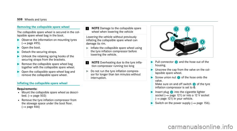
Pull connec tor4 and the hose out of the
housing. #
Unscr ew the cap from theva lve on the col‐
lapsible spare wheel. #
Screw union nut 1ofthe hose onto the
va lve.
Make sure on and off switch 3ofthe tyre
inflation compressor is set to0. #
Insert plug 4into the cigar ette lighter
soc ket (/ page 121) or into a 12V soc ket
( / page 121) in your vehicle. #
Switch on the po wer supp ly (/ page 156). 508
Wheels and tyres
Page 513 of 645
Note
s ontech nical data
Mercedes-AMG vehicles: be sure toobser ve
th e no tes in the Supplement. Otherwise, you
may failto recognise dangers.
The tech nical da tawa s de term ined in accord‐
ance with EU Directives. The data stated on ly
applies tovehicles with standard equipment. Yo u
can obtain fur ther information from a Mercedes-
Benz Service Centre.
Only for ce rtain countries: you can find vehi‐
cle-specific vehicle data in the EC-Certificate of
Conformity (CERTIFIC ATE OF CONFORMITY).
These documents are deli vered with your vehi‐
cle. On-board electronics
Note
s on tampering with the engine elec‐
tronics *
NO
TEPremature wearthro ugh improper
main tenance Improper maintenance may cause
vehicle
components towe ar more quickly and the
ve hicle's operating permit may be in valida‐
te d. #
Alw ays ha vewo rkon the engine elec‐
tronics and related components car ried
out at a qualified specialist workshop. Tw
o-w ayradios Note
s onfitting two-w ayradios &
WARNING Risk of accident due to
improper workon two-w ayradios
The elect romagnetic radiation from two-w ay
ra dios can inter fere with the on-board elec‐ tronics if RF transmit
ters are manipulated or
re trofitted inco rrectly.
This could jeopardise the operating saf ety of
th eve hicle. #
You should ha veall workon electrical
and electronic components car ried out
at a qualified specialist workshop. &
WARNING Risk of accident from incor‐
re ct ope ration of two-w ayradios
If yo u operate two- wayra dios inco rrectly in
th eve hicle, the electromagnetic radiation
could inter fere with the on-board electronics,
e.g.:
R ifth e two-w ayradio is not connec tedto
an exterior aerial
R ifth eex terior aerial is not cor rectly
mounted or is not of low reflection
This could jeopardise the operating saf ety of
th eve hicle. #
Have the lo w-reflection exterior aerial
fi tted at a qualified specialist workshop. 51 0
Tech nical da ta
Page 527 of 645
We
ights and loads Please obser
vethefo llowing no tesfo rth e speci‐
fi ed vehicle data:
R items of optional equipment increase the
unladen weight and reduce the pa yload.
R vehicle-specific weight information can be
fo und on theve hicle identification plate
(/ page 512).
Ro of load All models
Maximum
roof load 100kg Tr
ailer hitch Gene
ral no tes on the trailer hit ch Not all models can be used
for trailer operation
(/ page 252).
Modi fications tothe engine cooling sy stem may
be necessar y,depending on theve hicle model.
The retrofitting of a trailer hitch is only pe rmissi‐
ble if a towing capacity is specified in your vehi‐
cle documents. Fu
rther information can be obtained at a quali‐
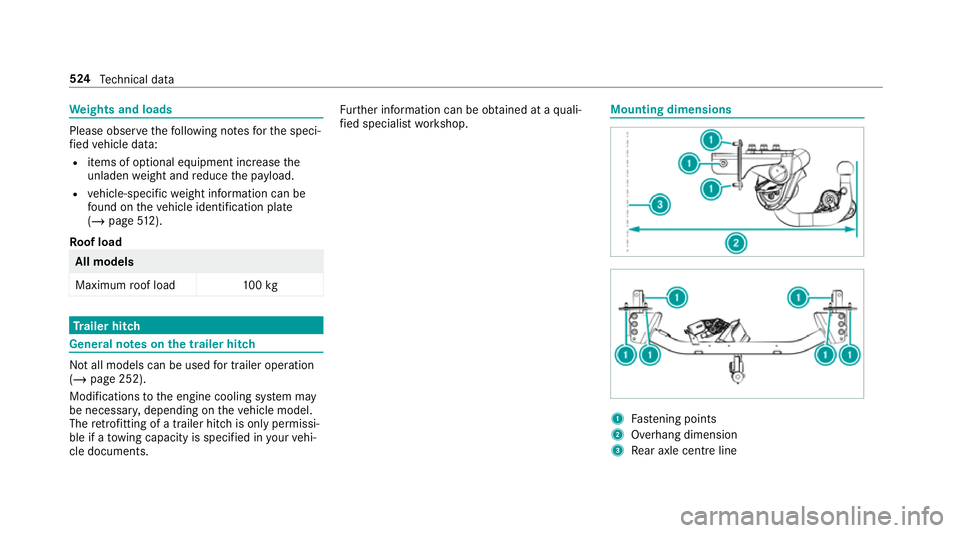
fi ed specialist workshop. Mounting dimensions
1
Fastening points
2 Overhang dimension
3 Rear axle centre line 524
Tech nical da ta
Page 528 of 645
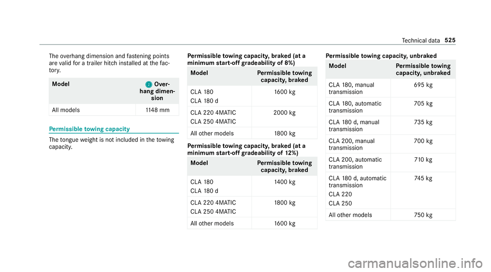
The
overhang dimension and fastening points
are valid for a trailer hitch ins talled at thefa c‐
to ry. Model
2 2Over‐
hang dimen‐ sion
All model s1 148 mm Pe
rm issible towing capacity The
tongue weight is not included in theto wing
capacity. Pe
rm issible towing capacit y,braked (at a
minimum start-off gradeability of 8%) Model
Perm issible towing
capacit y,braked
CLA 180
CLA 180 d 16
00 kg
CLA 220 4MATIC
CLA 250 4MATIC 2000
kg
All other models 1800 kg Pe
rm issible towing capacit y,braked (at a
minimum start-off gradeability of 12%) Model
Perm issible towing
capacit y,braked
CLA 180
CLA 180 d 14
00 kg
CLA 220 4MATIC
CLA 250 4MATIC 18
00 kg
All other models 1600 kg Pe
rm issible towing capacit y,unbraked Model
Perm issible towing
capacit y,unbraked
CLA 180, manual
transmission 695
kg
CLA 180, auto matic
transmission 705
kg
CLA 180 d, manual
transmission 73
5kg
CLA 200, manual
transmission 700
kg
CLA 200, automatic
transmission 71
0kg
CLA 180 d, auto matic
transmission
CLA 220
CLA 250 74
5kg
All other models 750kg Te
ch nical da ta525
Page 537 of 645
Display messages
Possible causes/consequences and M
MSolutions
If th e bat tery charge leve l is too lo w: #
Char gethe batter y.
To appl y: #
Switch off the ignition.
The electric parking brake is applied automaticall y.
If th e electric parking brake should not be applied, e.g. when washing theve hicle in an automatic car wash or when
having theve hicle towe d, lea vethe ignition switched on. This does not include having theve hicle towe d with the
re ar axle raised.
If th e electric parking brake is not applied automatically: #
Switch off the ignition and switch it back on. #
Release and then apply the electric parking brake manually (/ page189).
If it is still not possible toapply the electric parking brake: #
Consult a qualified specialist workshop. #
Where necessar y,also safeguard the par kedve hicle against rolling away.
To release: #
Ifth e conditions for auto matic release are fulfilled and the electric parking brake is not released automaticall y,
re lease the electric parking brake manually (/ page189). 534
Displaymessa ges and warning/indicator lamps
Page 547 of 645
Display messages
Possible causes/consequences and M
MSolutions
or #
Ifth e display message does not disappear, stop theve hicle in accordance with the tra ffic conditions and restart
th e engine.
Blind Spot Assist inopera-
tive *B
lind Spot Assist is malfunctioning. #
Consult a qualified specialist workshop.
Blind Spot Assist not availa-
ble when towing a trailer
See Owner's Manual *W
hen you es tablish the electrical connection tothe trailer, Blind Spot Assist is una vailable. #
Press the left-hand Touch Control and ackn owledge the display message.
Active Blind Spot Assist
currently unavailable See
Owner's Manual *A
ctive Blind Spot Assi stistemp orarily una vailable.
The sy stem limits ha vebeen reached (/ page246). #
Drive on.
Once the cause of the problem is no longer present, the sy stem will be available again.
or #
Ifth e display message does not disappear, stop theve hicle in accordance with the tra ffic conditions and restart
th e engine.
Active Blind Spot Assist
inoperative *A
ctive Blind Spot Assi stis malfunctioning. #
Consult a qualified specialist workshop. 544
Displaymessa ges and warning/indicator lamps