2019 MERCEDES-BENZ AMG GT ROADSTER weight
[x] Cancel search: weightPage 186 of 298
Display messages
Possible causes/consequences and
0050
0050Solutions Front
Front
Passenger
Passenger Air‐
Air‐
bag Disabled See
bag Disabled See
Operator's Manual Operator's Manual The front passenger front air bag is deactivated during the journey,
although:
R an adult
or
R a person of the corresponding stature is on the front passenger seat
If additional forces are applied to the seat, the system may interpret
the occupant's weight as lower than it actually is.
G WARNING
The front passenger front air bag does not deploy during an accident.
There is an increased risk of injury.
X Pull over and stop the vehicle safely as soon as possible, paying
attention to road and traffic conditions.
X Secure the vehicle against rolling away (Y page 127).
X Switch the ignition off.
X Have the occupant on the front passenger seat get out of the vehi-
cle.
X Keep the seat unoccupied, close the front passenger door and
switch on the ignition.
X Observe the PASSENGER AIR BAG indicator lamps in the center
console and the multifunction display and check the following:
Seat unoccupied and ignition switched on:
R a self-diagnosis is carried out. The PASSENGER AIR BAG OFF and
PASSENGER AIR BAG ON indicator lamps must light up simulta-
neously for approximately six seconds
R the PASSENGER AIR BAG OFF indicator lamp must then light up
and remain lit after the self-diagnosis. If the indicator lamp is on,
OCS (Occupant Classification System) has disabled the front
passenger front air bag (Y page 48)
R the display messages Front Passenger Airbag Enabled Front Passenger Airbag Enabled
See Operator's Manual
See Operator's Manual orFront Passenger Airbag Dis‐
Front Passenger Airbag Dis‐
abled See Operator's Manual
abled See Operator's Manual must not appear in the multi-
function display
X Wait for a period of at least 60 seconds until the necessary system
checks have been completed.
X Make sure that the display messages do not appear in the multi-
function display.
If these conditions are fulfilled, the front passenger seat can be occu- pied again. Whether the PASSENGER AIR BAG OFF indicator lamp
remains lit or goes out depends on how OCS classifies the occupant.
If the conditions are not fulfilled, the system is not operating correctly.
X Visit a qualified specialist workshop immediately.
For further information about the Occupant Classification System, see
(Y page 48). 184
Display
messagesOn-board computer and displays
Page 187 of 298
Display messages
Possible causes/consequences and
0050
0050Solutions Front
Front
Passenger
Passenger Air‐
Air‐
bag Enabled See
bag Enabled See
Operator's Manual Operator's Manual The front passenger front air bag and front passenger knee bag are
enabled during the journey, although:
R a child, a small adult or an object weighing less than the system's
weight threshold is located on the front passenger seat
or
R the front passenger seat is unoccupied
The system may detect objects or forces applying additional weight on
the seat.
G WARNING
The front passenger front air bag and the front passenger knee bag
may be deployed unintentionally.
There is an increased risk of injury. X Pull over and stop the vehicle safely as soon as possible, paying
attention to road and traffic conditions.
X Secure the vehicle against rolling away (Y page 127).
X Switch the ignition off.
X Open the front passenger door.
X Remove the child and the child restraint system from the front
passenger seat.
X Make sure that there are no objects on the seat adding to the
weight.
The system might otherwise detect the additional weight and inter-
pret the seat occupant's weight as greater than it actually is.
X Keep the seat unoccupied, close the front passenger door and
switch on the ignition.
X Observe the PASSENGER AIR BAG indicator lamps in the center
console and the multifunction display and check the following:
Seat unoccupied and ignition switched on:
R a self-diagnosis is carried out. The PASSENGER AIR BAG OFF and
PASSENGER AIR BAG ON indicator lamps must light up simulta-
neously for approximately six seconds
R the PASSENGER AIR BAG OFF indicator lamp must then light up
and remain lit after the self-diagnosis. If the indicator lamp is on,
OCS has disabled the front passenger front air bag and front
passenger knee bag (Y page 48)
R the display messages Front Passenger Airbag Enabled
Front Passenger Airbag Enabled
See Operator's Manual See Operator's Manual orFront Passenger Airbag Dis‐
Front Passenger Airbag Dis‐
abled See Operator's Manual
abled See Operator's Manual must not appear in the multi-
function display
X Wait for a period of at least 60 seconds until the necessary system
checks have been completed.
X Make sure that the display messages do not appear in the multi-
function display.
If these conditions are fulfilled, the front passenger seat can be occu- pied again. Whether the PASSENGER AIR BAG OFF or ON indicator
lamp remains lit or goes out depends on how OCS classifies the occu-
pant. Display
messages
185On-board computer and displays Z
Page 220 of 298
Stowage areas
Loading guidelines
G
DANGER
Combustion engines emit poisonous exhaust
gases such as carbon monoxide. Exhaust
gases can enter the vehicle interior if the
trunk lid is open while the engine is running,
especially if the vehicle is in motion. There is a risk of poisoning.
Always switch off the engine before opening
the trunk lid. Never drive with the trunk lid
open. G
WARNING
If objects, luggage or loads are not secured or not secured sufficiently, they could slip, tip
over or be flung around and thereby hit vehicle
occupants. There is a risk of injury, particu-
larly in the event of sudden braking or a sud-
den change in direction.
Always store objects so that they cannot be
flung around. Secure objects, luggage or
loads against slipping or tipping before the
journey. G
WARNING
The exhaust tail pipe and tail pipe trim can
become very hot. If you come into contact
with these parts of the vehicle, you could burn
yourself. There is a risk of injury.
Always be particularly careful around the
exhaust tail pipe and the tail pipe trim. Allow
these components to cool down before touch-
ing them.
! This vehicle is not designed to transport any
items on the trunk lid or to allow luggage car-
riers or equipment of any kind to be installed
to the trunk lid. Otherwise the vehicle and the
retractable hardtop could be damaged. The handling characteristics of a laden vehicle
are dependent on the distribution of the load
within the vehicle. For this reason, you should
observe the following notes when transporting a load:
R Never exceed the maximum permissible
gross vehicle mass or the gross axle weight
rating for the vehicle (including occupants).
The values are specified on the vehicle iden-
tification plate on the B-pillar of the driver's
door.
R The trunk is the preferred place to carry
objects.
R Position heavy loads as far forwards as pos-
sible and as low down in the trunk as possible.
R The load must not protrude above the upper
edge of the seat backrests.
R Secure the load with sufficiently strong and
wear-resistant tie-downs. Pad sharp edges for
protection. Stowage spaces
Important safety notes G
WARNING
If objects in the passenger compartment are
stowed incorrectly, they can slide or be
thrown around and hit vehicle occupants. In
addition, cup holders, open stowage spaces
and mobile phone brackets cannot always
retain all objects they contain. There is a risk of injury, particularly in the event of sudden
braking or a sudden change in direction.
R Always stow objects so that they cannot be
thrown around in such situations.
R Always make sure that objects do not pro-
trude from stowage spaces, parcel nets or
stowage nets.
R Close the lockable stowage spaces before
starting a journey.
R Always stow and secure heavy, hard, poin-
ted, sharp-edged, fragile or bulky objects in
the trunk.
Observe the loading guidelines (Y page 218).218
Stowage areasStowage and features
Page 260 of 298
X
Start the engine of your own vehicle.
X Let the engines run for several minutes.
X Before disconnecting the jumper cables, switch on an electrical consumer in your own vehicle,
e.g. the rear window heating or the lighting.
X When the jump-starting procedure is finished: first, remove the jumper cables from ground
point 0085and from negative terminal 0087of the donor battery, and then from positive terminal 0043
and positive terminal 0044of the donor battery. Begin each time at the contacts on your own vehicle
first.
X After removing the jumper cables, close cover 0083of positive terminal 0043.
X Only for vehicles with a carbon-fiber engine cover: insert the cover of the jump-starting
connection point. Make sure all mountings for the fasteners are positioned precisely behind the corresponding recesses in the cover.
Press the fasteners into the mountings. Turn the fasteners by 00C4of a turn to engage.
X Have the battery checked at a qualified specialist workshop.
Jump-starting is not considered to be a normal operating condition.
i Jumper cables and further information regarding jump-starting can be obtained at a qualified
specialist workshop. Towing and tow-starting
Important safety notes
G
WARNING
The rear axle locks when:
R the engine is not running
R the engine stalls while the vehicle is being
towed
R there is a malfunction in the power supply
or the vehicle's electrical system
There is a risk of an accident.
In the event of a breakdown, you should
always have the vehicle transported. G
WARNING
If the brake system or power steering is mal-
functioning and your vehicle is then towed
away, significantly more effort may be
required to steer and brake than is normally
required. There is a risk of an accident.
In such cases, use a tow bar. Before towing,
make sure that the steering moves freely. G
WARNING
When towing or tow-starting another vehicle
and its weight is greater than the permissible gross weight of your vehicle, the:
R the towing eye could detach itself
R the vehicle/trailer combination could roll-
over.
There is a risk of an accident.
When towing or tow-starting another vehicle,
its weight should not be greater than the per- missible gross weight of your vehicle.
Details on the permissible gross vehicle weight
of your vehicle can be found on the vehicle iden-
tification plate (Y page 287).
! Use the SmartKey instead of the Start/Stop
button when towing the vehicle.
Start the engine and keep it running. The
SmartKey is in position 0048in the ignition lock.
Set the transmission to 005Cusing the E-
SELECT selector lever. Make sure that you
then leave the SmartKey in position 0048.
Check the transmission position in the instru-
ment cluster.
! Make sure that the electric parking brake is
released. If the electric parking brake is faulty,
visit a qualified specialist workshop. 258
Towing and tow-startingBreakdown assistance
Page 274 of 298
sizes and corresponding pressures for tires
mounted at the factory.
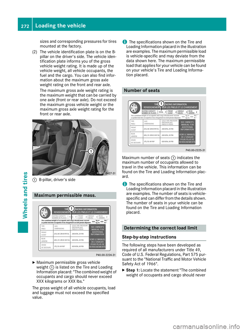
(2) The vehicle identification plate is on the B- pillar on the driver's side. The vehicle iden-
tification plate informs you of the gross
vehicle weight rating. It is made up of the
vehicle weight, all vehicle occupants, the
fuel and the cargo. You can also find infor-
mation about the maximum gross axle
weight rating on the front and rear axle.
The maximum gross axle weight rating is
the maximum weight that can be carried by one axle (front or rear axle). Do not exceed
the maximum gross vehicle weight or the
maximum gross axle weight rating for the
front or rear axle. 0043
B-pillar, driver's side Maximum permissible mass.
X
Maximum permissible gross vehicle
weight 0043is listed on the Tire and Loading
Information placard: "The combined weight of occupants and cargo should never exceed
XXX kilograms or XXX lbs."
The gross weight of all vehicle occupants, load
and luggage must not exceed the specified
value. i
The specifications shown on the Tire and
Loading Information placard in the illustration
are examples. The maximum permissible load is vehicle-specific and may deviate from the
data shown here. The maximum permissible
load that applies for your vehicle can be foundon your vehicle's Tire and Loading Informa-
tion placard. Number of seats
Maximum number of seats
0043indicates the
maximum number of occupants allowed to
travel in the vehicle. This information can be
found on the Tire and Loading Information plac-
ard.
i The specifications shown on the Tire and
Loading Information placard in the illustration
are examples. The number of seats is vehicle- specific and can differ from the details shown.
The number of seats in your vehicle can be
found on the Tire and Loading Information
placard. Determining the correct load limit
Step-by-step instructions The following steps have been developed as
required of all manufacturers under Title 49,
Code of U.S. Federal Regulations, Part 575 pur-
suant to the "National Traffic and Motor Vehicle
Safety Act of 1966".
X Step 1: Locate the statement "The combined
weight of occupants and cargo should never 272
Loading the vehicleWheels and tires
Page 275 of 298
exceed XXX kg or XXX lbs." on your vehicle’s
Tire and Loading Information placard.
X Step 2: Determine the combined weight of
the driver and passengers that will be riding in your vehicle.
X Step 3: Subtract the combined weight of the
driver and passengers from XXX kilograms or
XXX lbs.
X Step 4: The resulting figure equals the avail-
able amount of cargo and luggage load capa- city. For example, if the "XXX" amount equals
1400 lbs and there will be five 150-lb pas-
sengers in your vehicle, the amount of avail-
able cargo and luggage load capacity is
650 lbs (1400 - 750 (5 x 150) = 650 lbs).
X Step 5: Determine the combined weight of
luggage and cargo being loaded on the vehi-
cle. That weight may not safely exceed the
available cargo and luggage load capacity cal- culated in step 4. Example: steps 1 to 3
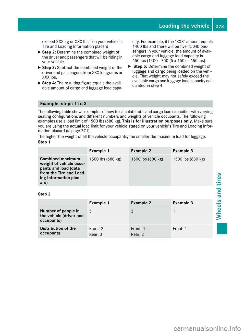
The following table shows examples of how to calculate total and cargo load capacities with varying
seating configurations and different numbers and weights of vehicle occupants. The following
examples use a load limit of 1500 lbs (680 kg). This is for illustration purposes only.Make sure
you are using the actual load limit for your vehicle stated on your vehicle's Tire and Loading Infor-
mation placard (Y page 271).
The higher the weight of all the vehicle occupants, the smaller the maximum load for luggage.
Step 1 Example 1 Example 2 Example 3
Combined maximum
weight of vehicle occu-
pants and load (data
from the Tire and Load-
ing Information plac-
ard)
1500 lbs (680 kg) 1500 lbs (680 kg) 1500 lbs (680 kg)
Step 2
Example 1 Example 2 Example 3
Number of people in
the vehicle (driver and
occupants)
5 3 1
Distribution of the
occupants
Front: 2
Rear: 3 Front: 1
Rear: 2 Front: 1Loading the vehicle
273Wheels and tires Z
Page 276 of 298
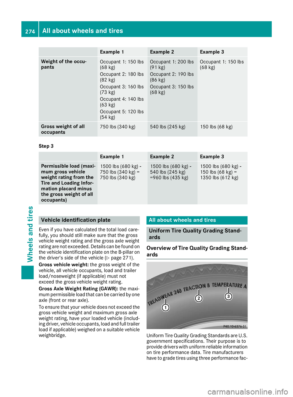
Example 1 Example 2 Example 3
Weight of the occu-
pants
Occupant 1: 150 lbs
(68 kg)
Occupant 2: 180 lbs
(82 kg)
Occupant 3: 160 lbs
(73 kg)
Occupant 4: 140 lbs
(63 kg)
Occupant 5: 120 lbs
(54 kg) Occupant 1: 200 lbs
(91 kg)
Occupant 2: 190 lbs
(86 kg)
Occupant 3: 150 lbs
(68 kg) Occupant 1: 150 lbs
(68 kg)
Gross weight of all
occupants
750 lbs (340 kg) 540 lbs (245 kg) 150 lbs (68 kg)
Step 3
Example 1 Example 2 Example 3
Permissible load (maxi-
mum gross vehicle
weight rating from the
Tire and Loading Infor-
mation placard minus
the gross weight of all
occupants)
1500 lbs (680 kg)
00F8
750 lbs (340 kg) =
750 lbs (340 kg) 1500 lbs (680 kg)
00F8
540 lbs (245 kg)
=960 lbs (435 kg) 1500 lbs (680 kg)
00F8
150 lbs (68 kg) =
1350 lbs (612 kg) Vehicle identification plate
Even if you have calculated the total load care-
fully, you should still make sure that the gross
vehicle weight rating and the gross axle weight
rating are not exceeded. Details can be found on
the vehicle identification plate on the B-pillar on
the driver's side of the vehicle (Y page 271).
Gross vehicle weight: the gross weight of the
vehicle, all vehicle occupants, load and trailer
load/noseweight (if applicable) must not
exceed the gross vehicle weight rating.
Gross Axle Weight Rating (GAWR): the maxi-
mum permissible load that can be carried by one axle (front or rear axle).
To ensure that your vehicle does not exceed thegross vehicle weight and maximum gross axle
weight rating, have your loaded vehicle (includ-
ing driver, vehicle occupants, load and full trailer
load if applicable) weighed on a suitable vehicle weighbridge. All about wheels and tires
Uniform Tire Quality Grading Stand-
ards
Overview of Tire Quality Grading Stand- ards Uniform Tire Quality Grading Standards are U.S.
government specifications. Their purpose is to
provide drivers with uniform reliable information on tire performance data. Tire manufacturers
have to grade tires using three performance fac- 274
All about wheels and tiresWheels and tires
Page 280 of 298
The speed rating of tires mounted at the factory
may be higher than the maximum design speed permitted by the electronic speed limiter.
Make sure that your tires have the required
speed rating, e.g. when buying new tires. The
required speed rating for your vehicle can be
found in the "Tires" section (Y page 285).
Further information about reading tire data can
be obtained from any qualified specialist work-
shop.
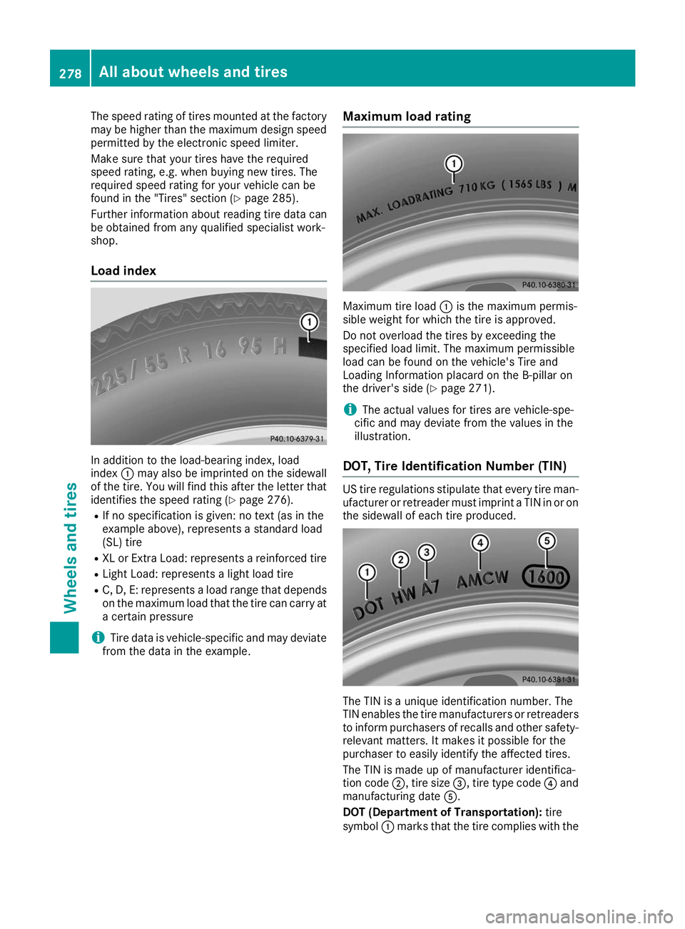
Load index In addition to the load-bearing index, load
index
0043may also be imprinted on the sidewall
of the tire. You will find this after the letter that identifies the speed rating (Y page 276).
R If no specification is given: no text (as in the
example above), represents a standard load
(SL) tire
R XL or Extra Load: represents a reinforced tire
R Light Load: represents a light load tire
R C, D, E: represents a load range that depends
on the maximum load that the tire can carry at a certain pressure
i Tire data is vehicle-specific and may deviate
from the data in the example. Maximum load rating Maximum tire load
0043is the maximum permis-
sible weight for which the tire is approved.
Do not overload the tires by exceeding the
specified load limit. The maximum permissible
load can be found on the vehicle's Tire and
Loading Information placard on the B-pillar on
the driver's side (Y page 271).
i The actual values for tires are vehicle-spe-
cific and may deviate from the values in the
illustration.
DOT, Tire Identification Number (TIN) US tire regulations stipulate that every tire man-
ufacturer or retreader must imprint a TIN in or on the sidewall of each tire produced. The TIN is a unique identification number. The
TIN enables the tire manufacturers or retreaders to inform purchasers of recalls and other safety-
relevant matters. It makes it possible for the
purchaser to easily identify the affected tires.
The TIN is made up of manufacturer identifica-
tion code 0044, tire size 0087, tire type code 0085and
manufacturing date 0083.
DOT (Department of Transportation): tire
symbol 0043marks that the tire complies with the 278
All about wheels and tiresWheels and tires