2019 MASERATI QUATTROPORTE warning light
[x] Cancel search: warning lightPage 126 of 396

To activate lane change function, tap
the lever up or down once, without
moving beyond the detent. The turn
signals (right or left) will flash three
times then automatically turn off.
This function is useful when
overtaking or changing lanes.
NOTE:
• If either light remains on and does
not flash, or flashes at a fast rate,
check for a defective outside light. If
an indicator on the instrument
cluster fails while moving the lever,
then the turn indicator could be
defective.
• The message that a turn signal is on
will appear in the instrument cluster
and a continuous chime will sound if
the vehicle is driven more than 1 mile
(1.6 km) with either turn signal on. High Beams and Flashing
To switch on the high beams with the
light switch in headlamp
or
“AUTO” position, shift the
multifunction lever onward.
The blue telltale
will illuminate on
the tachometer.
By pulling the lever backward (toward
the steering wheel) you switch off the
high beams and switch on the low
beams. You can signal another vehicle with
your headlights by lightly pulling the
multifunction lever toward you. This
will turn on the high beams headlights
until the lever is released.
Flashing occurs also with lights off
(lights switch in position “0”) if the
ignition switch is RUN position.
CAUTION!
The high beams can only be switched
on manually by pushing the
multifunction lever forward.
WARNING!
If the high beams are activated, they
will turn on automatically every time
the low beams are switched on either
manually or automatically. WeUnderstanding the Vehicle
3
122
Page 127 of 396

recommend therefore that you switch
them off when they are no longer
necessary and every time the twilight
sensor deactivates the external lights.
Automatic High Beams
The
Automatic High Beam headlight
control system provides increased
forward lighting at night by
automating high beam control
through the use of the forward digital
camera mounted behind the rearview
mirror, which is the same one used
also by the Lane Departure Warning
(LDW) system. This camera detects
vehicle specific light and automatically
switches from high beams to low
beams until the approaching vehicle is
out of view. Furthermore, the digital
camera is able to detect the urban
areas and the inhabited centers and to
turn off the high beams when driving
near of one of them.
The high beam can be turned back on
if there are all the necessary
conditions and if the vehicle speed
exceed 21.7 mph (35 km/h).
The “Auto High Beam Assist” feature
can be turned on or off using the
MTC+ System. Refer to “MTC+
Settings” in section "Dashboard
Instruments and Controls" for further
information. The function is enabled only if the
brightness sensor detects the right
lighting conditions.
To activate this function:
• Shift the multifunction lever onward
.
• Put the headlight switch in “AUTO”
position.
• Enable the “Auto High Beam Assist”
function on MTC+.
After these steps, the green indicator
on the upper right side of the TFT
display comes on. NOTE:
Broken, muddy, or obstructed
headlights and taillights of vehicles in
the field of view will cause headlights
to remain on longer (closer to the
vehicle). Also, dirt, film, and other
obstructions on the windshield or
camera lens will cause the system to
function improperly.
If the windshield or Automatic High
Beam headlight control mirror is
replaced, the mirror must be re-aimed
to ensure proper performance. See
your local Authorized Maserati Dealer .
Interior Lights The interior and exterior approach
lights turn on and off when
entering/exiting the vehicle (see
“Illuminated Entry/Exit” in section
"Before Starting" for further
information).
The brightness of the lights can be
manually adjusted with the regulator
positioned beside the light switch.
To protect the battery, the interior
lights will turn off automatically 10
minutes after the ignition switch has
been shifted to OFF . This occurs if the
interior lights were turned on
manually or by opening of a door. The
glove box light, share the sameUnderstanding the Vehicle
3
123
Page 130 of 396
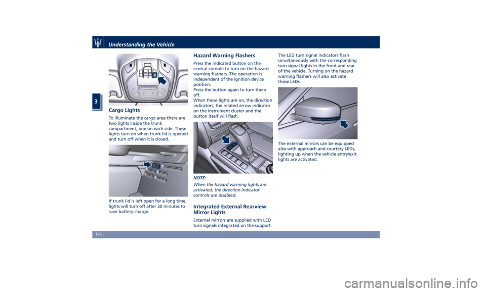
Cargo Lights To illuminate the cargo area there are
two lights inside the trunk
compartment, one on each side. These
lights turn on when trunk lid is opened
and turn off when it is closed.
If trunk lid is left open for a long time,
lights will turn off after 30 minutes to
save battery charge. Hazard Warning Flashers Press the indicated button on the
central console to turn on the hazard
warning flashers. The operation is
independent of the ignition device
position.
Press the button again to turn them
off.
When these lights are on, the direction
indicators, the related arrow indicator
on the instrument cluster and the
button itself will flash.
NOTE:
When the hazard warning lights are
activated, the direction indicator
controls are disabled.
Integrated External Rearview
Mirror Lights External mirrors are supplied with LED
turn signals integrated on the support. The LED turn signal indicators flash
simultaneously with the corresponding
turn signal lights in the front and rear
of the vehicle. Turning on the hazard
warning flashers will also activate
these LEDs.
The external mirrors can be equipped
also with approach and courtesy LEDs,
lighting up when the vehicle entry/exit
lights are activated.Understanding the Vehicle
3
126
Page 134 of 396
(Continued)
servicing your vehicle. For more
information go to:
www.P65Warnings.ca.gov/passenger-
vehicle
Heated Windshield Washer Nozzles
T
o avoid fluid freezing inside at low
external temperatures, the fluid supply
nozzles can be heated by internal
resistors.
Interior Features Electric Power Outlets The vehicle is equipped with four 12
Volt (13 Amp) electric power outlets,
two available for the front seat
passengers, one for rear seat
passengers and one fitted in the trunk
compartment.
In vehicles equipped with “Smoking
Kit” the electric power outlet inside
the cupholder is replaced with a
cigarette lighter.
All power outlets are supplied only
when the engine is started or the
ignition device set to ACC or RUN .
Power outlets are protected by a fuse.
Insert a cigar lighter or accessory plug
into the power outlets to ensure
proper operation. Otherwise, check
the matching fuse integrity, see “Fuse
Replacement” in section “Maintenance
and Care” for further information.
CAUTION!
• Do not plug in accessories that
exceed the maximum power of 160
Watts (13 Amps) at 12 Volts.
• Power outlets are designed for
accessory plugs only. Do not insert
any other object in the power outlets as this will damage the outlet and
blow the fuse. Damages caused by
improper use of the power outlet are
not covered by the New Vehicle
Limited Warranty.
WARNING!
To avoid serious injury or death:
• Only devices designed for use in this
type of outlet should be inserted
into any 12 Volt outlet.
• Replacing the fuses that protect
power outlets with others of higher
amperage, there is the risk of fire.
• Do not touch with wet hands.
• Close the lids when the plug is not
used and while driving the vehicle.
• If this outlet is mishandled, it may
cause an electric shock and failure.
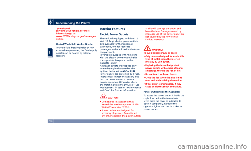
Power Outlet inside the Cupholder
To access the power outlet is inside the
cupholder beside the transmission
lever, press the cover as indicated to
open it completely. Remove the
cigarette lighter and use its socket as
power outlet.Understanding the Vehicle
3
130
Page 140 of 396
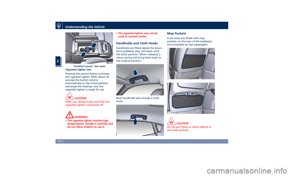
Cigarette Lighter Use
Pressing the central button activates
the cigarette lighter. After about 20
seconds the button returns
automatically to the initial position
and stops the heating: now the
cigarette lighter is ready for use.
CAUTION!
After use, always make sure that the
cigarette lighter is switched off.
WARNING!
• The cigarette lighter reaches high
temperatures. Handle it carefully and
do not allow children to use it. • The cigarette lighter may not be
used as a power outlet.
Handholds and Cloth Hooks Handholds are fitted above the doors.
Once grabbed, they will lower until
the block position. When released, a
return spring will bring them back to
the original position.
Rear handholds also include a cloth
hook. Map Pockets Front seats are fitted with map
pockets, on the rear of the seatbacks,
and accessible by rear passengers.
CAUTION!
Do not put heavy or sharp objects in
the mesh pockets.“Comfort Luxury” rear seatsUnderstanding the Vehicle
3
136
Page 143 of 396
Cargo Area WARNING!
To help protect against personal
injury, passengers must not be seated
in the rear cargo area. The rear cargo
space is intended for load carrying
purposes only, not for passengers,
who should sit in seats and use seat
belts.
Vehicle Load Carrying Capacity The load carrying capacity of your
vehicle is shown on the vehicle
emission control label positioned on
the rear driver door's ledge.
The information indicated on the label
concerns passengers and luggage
loading operations. Do not exceed the specified Gross
Vehicle Weight Rating (GVWR) or the
Gross Axle Weight Rating (GAWR),
both front and rear.
The GVWR is the total allowable
weight of your vehicle. This includes
driver, passengers, and cargo.
The total load must be limited so that
you do not exceed the GVWR
indicated on the label.
Vehicle Loading WARNING!
• Improper weight distribution can
have an adverse effect on the way
the vehicle steers, handles and the
way the brakes operate.
• Never drive with the trunk lid open.
Exhaust gases can enter the
passenger compartment.
• Do not pile luggage or cargo higher
than the top of the seatback. This
could impair visibility or become
dangerous in a sudden stop or
collision.
The trunk is the most suitable place to
load
bulky and heavy objects onboard
the vehicle. The maximum allowable load on the floor of the trunk is 440 lb
(200 kg).
To load your vehicle properly, store
heavier items below and be sure you
distribute their weight as evenly as
possible.
Stow all loose items securely before
start driving as they could move
during the trip.
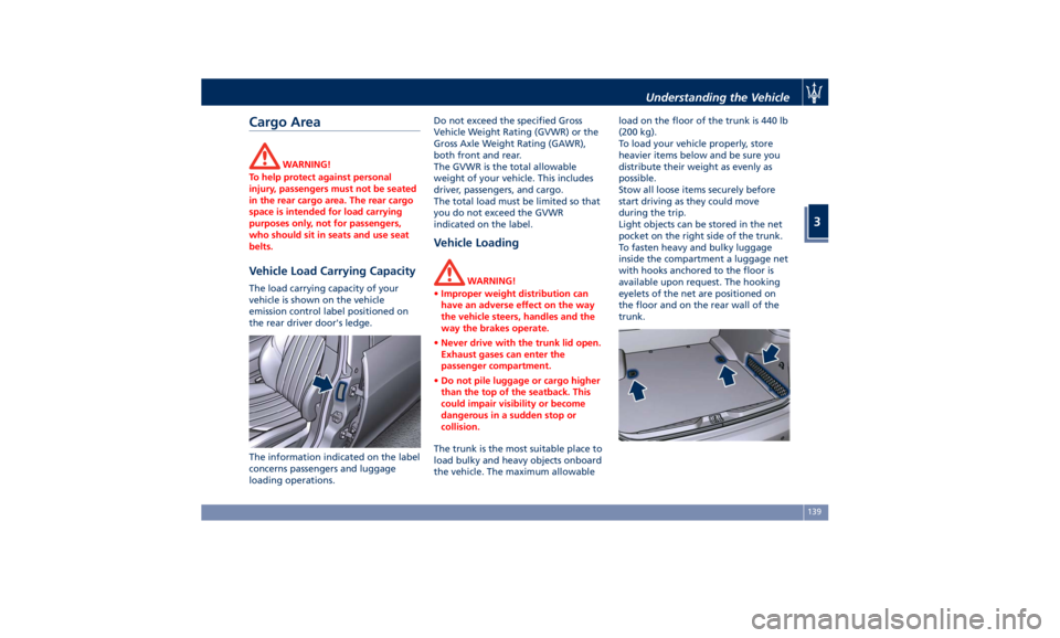
Light objects can be stored in the net
pocket on the right side of the trunk.
To fasten heavy and bulky luggage
inside the compartment a luggage net
with hooks anchored to the floor is
available upon request. The hooking
eyelets of the net are positioned on
the floor and on the rear wall of the
trunk.Understanding the Vehicle
3
139
Page 147 of 396
open, then adjust the sunroof opening
to minimise the buffeting.
Ignition Off Operation The power sunroof controls will
remain active for up to approximately
ten minutes after the ignition switch is
in OFF position. Opening either front
door will cancel this feature. The
ignition system timing can be set using
the MTC+ System (see “MTC+
Settings” in section “Dashboard
Instruments and Controls”).
Sunroof Maintenance Use only a nonabrasive cleaner and a
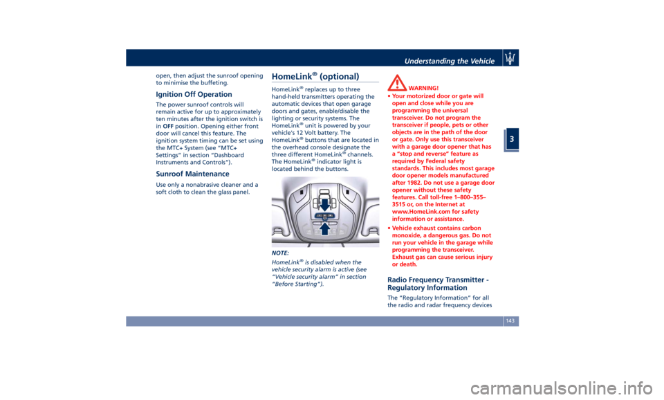
soft cloth to clean the glass panel. HomeLink ®
(optional) HomeLink ®
replaces up to three
hand-held transmitters operating the
automatic devices that open garage
doors and gates, enable/disable the
lighting or security systems. The
HomeLink ®
unit is powered by your
vehicle's 12 Volt battery. The
HomeLink ®
buttons that are located in
the overhead console designate the
three different HomeLink ®
channels.
The HomeLink ®
indicator light is
located behind the buttons.
NOTE:
HomeLink ®
is disabled when the
vehicle security alarm is active (see
“Vehicle security alarm” in section
“Before Starting”). WARNING!
• Your motorized door or gate will
open and close while you are
programming the universal
transceiver. Do not program the
transceiver if people, pets or other
objects are in the path of the door
or gate. Only use this transceiver
with a garage door opener that has
a “stop and reverse” feature as
required by Federal safety
standards. This includes most garage
door opener models manufactured
after 1982. Do not use a garage door
opener without these safety
features. Call toll-free 1–800–355–
3515 or, on the Internet at
www.HomeLink.com for safety
information or assistance.
• Vehicle exhaust contains carbon
monoxide, a dangerous gas. Do not
run your vehicle in the garage while
programming the transceiver.
Exhaust gas can cause serious injury
or death.
Radio Frequency Transmitter -
Regulatory Information The “Regulatory Information” for all
the radio and radar frequency devicesUnderstanding the Vehicle
3
143
Page 156 of 396
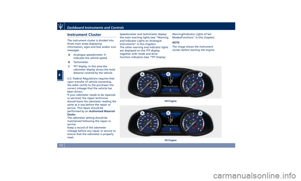
Instrument Cluster The instrument cluster is divided into
three main areas displaying
information, signs and text and/or icon
messages.
A Analogue speedometer. It
indicates the vehicle speed.
B Tachometer.
C TFT display. In this area the
odometer display shows the total
distance covered by the vehicle.
U.S. Federal Regulations requires that
upon transfer of vehicle ownership,
the seller certify to the purchaser the
correct mileage that the vehicle has
been driven.
If your odometer needs to be repaired
or serviced, the repair technician
should leave the odometer reading the
same as it was before the repair or
service. This repair should be
performed by an Authorized Maserati
Dealer .
The odometer setting should be
maintained following the repair or
service.
Keep a record of the odometer
mileage before any repair or service to
ensure that the odometer is properly
reset. Speedometer and tachometer display
the main warning lights (see “Warning
and Indicator Lights on Analogue
Instruments” in this chapter).
The other warning and indicator lights
are displayed on the TFT display
together with mode and drive
function indicators (see “TFT Display: Warning/Indicator Lights of Set
Modes/Functions” in this chapter).
NOTE:
The image shows the instrument
cluster before starting the engine.
V8 Engine
V6 EngineDashboard Instruments and Controls
4
152