2019 MASERATI QUATTROPORTE ECO mode
[x] Cancel search: ECO modePage 149 of 396
The quick flashing light indicates that
the channel with the new frequency
has been acquired and programmed
correctly by the HomeLink ®
system.
NOTE:
The distance necessary between the
portable hand-held transmitter and
the HomeLink ®
in the vehicle depends
on the system you wish to program.
Probably it will be necessary to try
several times. Upon every attempt,
keep the setting position for at least
15 seconds before trying again.
Synchronizing the Rolling Codes
At the end of the previously-described
programming, if the HomeLink ®
has
been programmed for a rolling code
system, it will be necessary to
synchronize it to ensure its correct
operation.
• Locate the “LEARN” or “TRAINING”
setting button of the opening motor.
Firmly press it and then release it. On
some garage door openers/devices
there may be a light that blinks
when the garage door opener/device
is in the LEARN/TRAIN mode. NOTE:
You have 30 seconds to initiate the
next step after the setting button has
been pressed.
• Return to the vehicle and press the
programmed HomeLink ®
button for
two seconds and then release it.
• Repeat this operation a second time.
If the garage door opening device
activates, the programming/
synchronization phase is complete.
NOTE:
If the garage door opening device
does not activate, press the button a
third time for two seconds and then
release it to complete the
programming/synchronization phase.
• To program the remaining two
HomeLink ®
buttons, repeat each
step for each remaining button. DO
NOT erase the channels.
Reprogramming a Single HomeLink ®
Button
To reprogram a channel that has been
previously trained, follow these steps:
• Place the ignition device to the RUN
position without starting the engine.
• Press and hold the desired
HomeLink ®
button. • Without releasing the button
proceed with “Programming the
hand-held transmitters” from second
step and follow all remaining steps.
System with Devices Without
Rolling Code Programming the Hand-held
Transmitters
Programming garage door openers
manufactured before 1995.
• Turn the ignition device to the RUN
position without starting the engine.
• Place the hand-held transmitter 1 to
3 inches (5 to 30 cm) away from the
HomeLink ®
button you wish to
program.
• Simultaneously press and hold both
buttons until the indicator light
starts flashing quickly; then release
both buttons.
The quick flashing light indicates that
the channel with the new frequency
has been acquired and programmed
correctly by the HomeLink ®
system.Understanding the Vehicle
3
145
Page 156 of 396
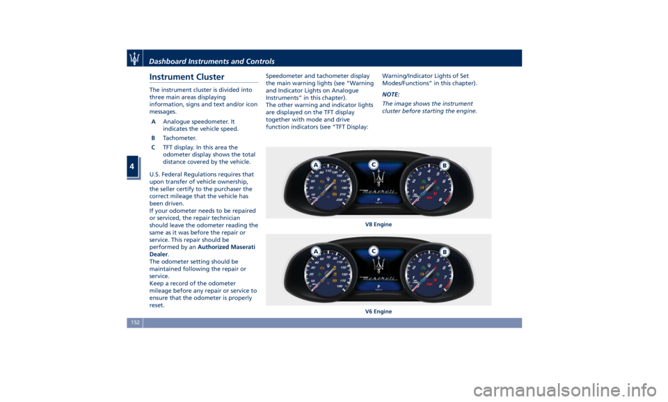
Instrument Cluster The instrument cluster is divided into
three main areas displaying
information, signs and text and/or icon
messages.
A Analogue speedometer. It
indicates the vehicle speed.
B Tachometer.
C TFT display. In this area the
odometer display shows the total
distance covered by the vehicle.
U.S. Federal Regulations requires that
upon transfer of vehicle ownership,
the seller certify to the purchaser the
correct mileage that the vehicle has
been driven.
If your odometer needs to be repaired
or serviced, the repair technician
should leave the odometer reading the
same as it was before the repair or
service. This repair should be
performed by an Authorized Maserati
Dealer .
The odometer setting should be
maintained following the repair or
service.
Keep a record of the odometer
mileage before any repair or service to
ensure that the odometer is properly
reset. Speedometer and tachometer display
the main warning lights (see “Warning
and Indicator Lights on Analogue
Instruments” in this chapter).
The other warning and indicator lights
are displayed on the TFT display
together with mode and drive
function indicators (see “TFT Display: Warning/Indicator Lights of Set
Modes/Functions” in this chapter).
NOTE:
The image shows the instrument
cluster before starting the engine.
V8 Engine
V6 EngineDashboard Instruments and Controls
4
152
Page 161 of 396
continuous sound will advise the
driver to turn the signal off.
If the indicator flashes at a fast rate,
check for a defective outside indicator
light bulb.
Seat Belt Reminder Light
When the ignition switch is in
RUN , the seat belt reminder
light will light up for a few
seconds as a bulb check.
During the bulb check, you will hear
an acoustic signal if one or both front
seat belts are unbuckled.
After the bulb check or while driving,
if a seat belt is unbuckled, together
with the acoustic signal the seat belt
reminder light will light up and a
message will indicate which belt is not
fastened.
WARNING!
Maserati urges you to use the seat
belts correctly fastened and adjusted
at all times. Correct use of the seat
belts can help reduce the risk of
serious injury in the event of an
accident. Do not pass seat belts over
sharp edges. They could tear. Do not
pin anything to the seat belts. This
could reduce their initial strength and cause them to tear in the event of a
crash.
Refer to “Occupants Restraint
Systems”
in section
“Before Starting”
for further information.
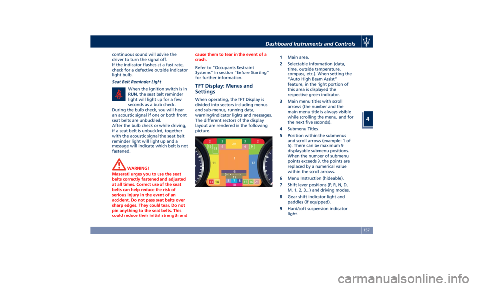
TFT Display: Menus and
Settings When operating, the TFT Display is
divided into sectors including menus
and sub-menus, running data,
warning/indicator lights and messages.
The different sectors of the display
layout are rendered in the following
picture. 1 Main area.
2 Selectable information (data,
time, outside temperature,
compass, etc.). When setting the
“Auto High Beam Assist”
feature, in the right portion of
this area is displayed the
respective green indicator.
3 Main menu titles with scroll
arrows (the number and the
main menu title is always visible
while scrolling the menu, and for
the next five seconds).
4 Submenu Titles.
5 Position within the submenus
and scroll arrows (example: 1 of
5). There can be maximum 9
displayable submenu positions.
When the number of submenu
points exceeds 9, the points are
replaced by a numerical value
within the scroll arrows.
6 Menu Instruction (hideable).
7 Shift lever positions (P, R, N, D,
M, 1, 2, 3...) and driving modes.
8 Gear shift indicator light and
paddles (if equipped).
9 Hard/soft suspension indicator
light.Dashboard Instruments and Controls
4
157
Page 162 of 396
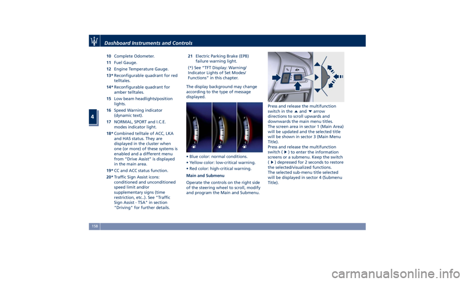
10 Complete Odometer.
11 Fuel Gauge.
12 Engine Temperature Gauge.
13* Reconfigurable quadrant for red
telltales.
14* Reconfigurable quadrant for
amber telltales.
15 Low beam headlights/position
lights.
16 Speed Warning indicator
(dynamic text).
17 NORMAL, SPORT and I.C.E.
modes indicator light.
18* Combined telltale of ACC, LKA
and HAS status. They are
displayed in the cluster when
one (or more) of these systems is
enabled and a different menu
from “Drive Assist” is displayed
in the main area.
19* CC and ACC status function.
20* Traffic Sign Assist icons:
conditioned and unconditioned
speed limit and/or
supplementary signs (time
restriction, etc..). See "Traffic
Sign Assist - TSA" in section
"Driving" for further details. 21 Electric Parking Brake (EPB)
failure warning light.
(*) See “TFT Display: Warning/
Indicator Lights of Set Modes/
Functions” in this chapter.
The display background may change
according to the type of message
displayed.
• Blue color: normal conditions.
• Yellow color: low-critical warning.
• Red color: high-critical warning.
Main and Submenu
Operate the controls on the right side
of the steering wheel to scroll, modify
and program the Main and Submenu. Press and release the multifunction
switch in the
and arrow
directions to scroll upwards and
downwards the main menu titles.
The screen area in sector 1 (Main Area)
will be updated and the selected title
will be shown in sector 3 (Main Menu
Title).
Press and release the multifunction
switch (
) to enter the information
screens or a submenu. Keep the switch
(
) depressed for 2 seconds to restore
the selected/visualized functions.
The selected sub-menu title selected
will be displayed in sector 4 (Submenu
Title).Dashboard Instruments and Controls
4
158
Page 163 of 396
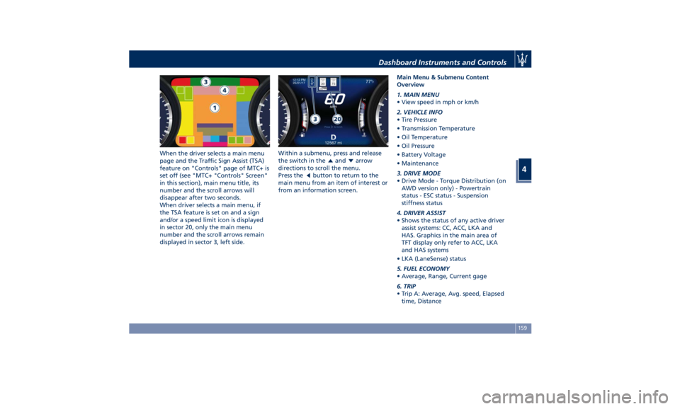
When the driver selects a main menu
page and the Traffic Sign Assist (TSA)
feature on "Controls" page of MTC+ is
set off (see "MTC+ "Controls" Screen"
in this section), main menu title, its
number and the scroll arrows will
disappear after two seconds.
When driver selects a main menu, if
the TSA feature is set on and a sign
and/or a speed limit icon is displayed
in sector 20, only the main menu
number and the scroll arrows remain
displayed in sector 3, left side. Within a submenu, press and release
the switch in the
and arrow
directions to scroll the menu.
Press the
button to return to the
main menu from an item of interest or
from an information screen. Main Menu & Submenu Content
Overview
1. MAIN MENU
• View speed in mph or km/h
2. VEHICLE INFO
• Tire Pressure
• Transmission Temperature
• Oil Temperature
• Oil Pressure
• Battery Voltage
• Maintenance
3. DRIVE MODE
• Drive Mode - Torque Distribution (on
AWD version only) - Powertrain
status - ESC status - Suspension
stiffness status
4. DRIVER ASSIST
• Shows the status of any active driver
assist systems: CC, ACC, LKA and
HAS. Graphics in the main area of
TFT display only refer to ACC, LKA
and HAS systems
• LKA (LaneSense) status
5. FUEL ECONOMY
• Average, Range, Current gage
6. TRIP
• Trip A: Average, Avg. speed, Elapsed
time, DistanceDashboard Instruments and Controls
4
159
Page 167 of 396
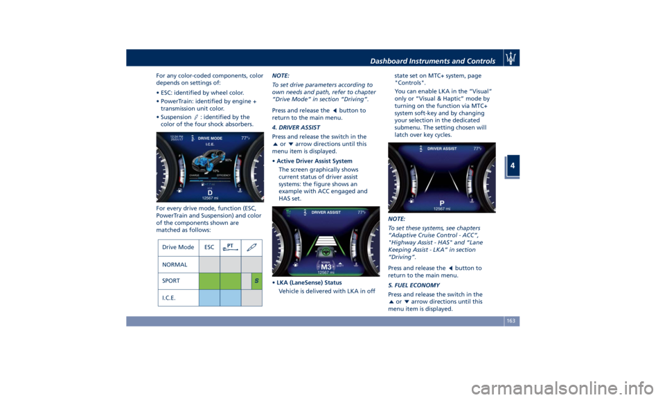
For any color-coded components, color
depends on settings of:
• ESC: identified by wheel color.
• PowerTrain: identified by engine +
transmission unit color.
• Suspension
: identified by the
color of the four shock absorbers.
For every drive mode, function (ESC,
PowerTrain and Suspension) and color
of the components shown are
matched as follows: NOTE:
To set drive parameters according to
own needs and path, refer to chapter
“Drive Mode” in section “Driving”.
Press and release the
button to
return to the main menu.
4. DRIVER ASSIST
Press and release the switch in the
or arrow directions until this
menu item is displayed.
• Active Driver Assist System
The screen graphically shows
current status of driver assist
systems: the figure shows an
example with ACC engaged and
HAS set.
• LKA (LaneSense) Status
Vehicle is delivered with LKA in off state set on MTC+ system, page
"Controls".
You can enable LKA in the ”Visual”
only or “Visual & Haptic” mode by
turning on the function via MTC+
system soft-key and by changing
your selection in the dedicated
submenu. The setting chosen will
latch over key cycles.
NOTE:
To set these systems, see chapters
“Adaptive Cruise Control - ACC”,
"Highway Assist - HAS" and “Lane
Keeping Assist - LKA” in section
“Driving”.
Press and release the
button to
return to the main menu.
5. FUEL ECONOMY
Press and release the switch in the
or arrow directions until this
menu item is displayed.Dashboard Instruments and Controls
4
163
Page 173 of 396
“Time” is selected). A check mark will
remain next to the previously-selected
item until a new selection is made.
Press and release the switch (
)to
select an item. The notification of
setting saved appears as a popup for 2
seconds, then the display will show
the last-modified item.
Press and release the
button to
return to the “Screen Setup”
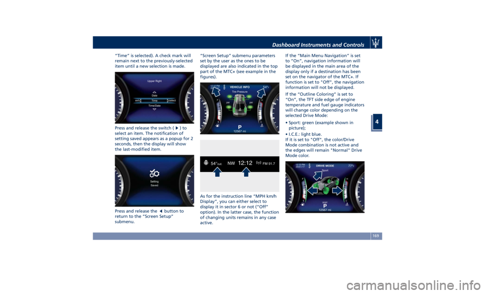
submenu. “Screen Setup” submenu parameters
set by the user as the ones to be
displayed are also indicated in the top
part of the MTC+ (see example in the
figures).
As for the instruction line “MPH km/h
Display”, you can either select to
display it in sector 6 or not (“Off”
option). In the latter case, the function
of changing units remains in any case
active. If the “Main Menu Navigation” is set
to “On”, navigation information will
be displayed in the main area of the
display only if a destination has been
set on the navigator of the MTC+. If
function is set to "Off", the navigation
information will not be displayed.
If the “Outline Coloring” is set to
“On”, the TFT side edge of engine
temperature and fuel gauge indicators
will change color depending on the
selected Drive Mode:
• Sport: green (example shown in
picture);
• I.C.E.: light blue.
If it is set to "Off", the color/Drive
Mode combination is not active and
the edges will remain "Normal" Drive
Mode color.Dashboard Instruments and Controls
4
169
Page 174 of 396
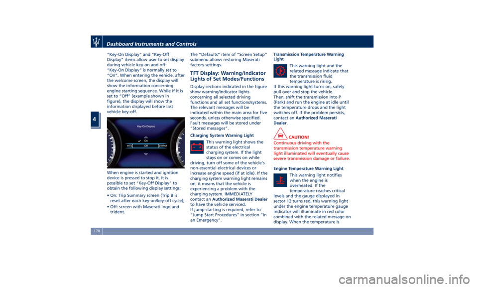
“Key-On Display” and “Key-Off
Display” items allow user to set display
during vehicle key-on and off.
“Key-On Display” is normally set to
“On”. When entering the vehicle, after
the welcome screen, the display will
show the information concerning
engine starting sequence. While if it is
set to “Off” (example shown in
figure), the display will show the
information displayed before last
vehicle key-off.
When engine is started and ignition
device is pressed to stop it, it is
possible to set “Key-Off Display” to
obtain the following display settings:
• On: Trip Summary screen (Trip B is
reset after each key-on/key-off cycle);
• Off: screen with Maserati logo and
trident. The “Defaults” item of “Screen Setup”
submenu allows restoring Maserati
factory settings.
TFT Display: Warning/Indicator
Lights of Set Modes/Functions Display sections indicated in the figure
show warning/indicator lights
concerning all selected driving
functions and all set functions/systems.
The relevant messages will be
indicated within the main area for five
seconds, unless otherwise specified.
Fault messages will be stored under
“Stored messages”.
Charging System Warning Light
This warning light shows the
status of the electrical
charging system. If the light
stays on or comes on while
driving, turn off some of the vehicle's
non-essential electrical devices or
increase engine speed (if at idle). If the
charging system warning light remains
on, it means that the vehicle is
experiencing a problem with the
charging system. IMMEDIATELY
contact an Authorized Maserati Dealer
to have the vehicle serviced.
If jump starting is required, refer to
“Jump Start Procedures” in section “In
an Emergency”. Transmission Temperature Warning
Light
This warning light and the
related message indicate that
the transmission fluid
temperature is rising.
If this warning light turns on, safely
pull over and stop the vehicle.
Then, shift the transmission into P
(Park) and run the engine at idle until
the temperature drops and the light
switches off. If the problem persists,
contact an Authorized Maserati
Dealer .
CAUTION!
Continuous driving with the
transmission temperature warning
light illuminated will eventually cause
severe transmission damage or failure.
Engine Temperature Warning Light
This
warning light
notifies
when the engine is
overheated. If the
temperature reaches critical
levels and the gauge displayed in
sector 12 turns red, this warning light
under the engine temperature gauge
indicator will illuminate in red color
combined with the related message on
display. When the temperature isDashboard Instruments and Controls
4
170