2019 MASERATI QUATTROPORTE fuse
[x] Cancel search: fusePage 77 of 396

• It is dangerous to try to repair any
part of the air bag system without
the necessary know-how.
• Do not attempt to modify any part
of your air bag system. The air bag
may inflate accidentally or may not
function properly if modifications
are made. Take your vehicle to an
Authorized Maserati Dealer for any
air bag system service. If your seat
including your trim cover and
cushion needs to be serviced in any
way (including removal or
loosening/tightening of seat
attachment bolts), take the vehicle
to an Authorized Maserati Dealer.
• Only Maserati manufacturer
approved seat accessories may be
used. If it is necessary to modify the
air bag system for persons with
disabilities, contact an Authorized
Maserati Dealer.
• If the speedometer, Rev Counter, or
any engine related gauges are not
working, the Occupant Restraint
Controller (ORC) may also be
disabled. The air bags may not be
ready to inflate for your protection.
Promptly check the fuse block for
blown fuses. To identify the air bag
fuse see “Fuse Replacement” in
section "Maintenance and Care". See an Authorized Maserati Dealer if the
fuse does not fix the problem.
Transport of persons with
disability If it is necessary to modify the
advanced air bag system of your
vehicle to accommodate a person with
disabilities, contact an Authorized
Maserati Dealer .
WARNING!
• The advanced air bag system of your
vehicle is not designed to protect
adults with disabilities that require
deactivation of the passenger or
driver air bag.
• If you or another occupant is an
adult with a medical condition that
requires air bag deactivation, please
contact an Authorized Maserati
Dealer. For further information on
disabled driver or passengers see
http://www.safercar.gov.
• As long as the air bag is activated,
persons with disabilities are advised
not to travel in the front seat in
order to avoid the risk of serious
injuries or death, even in minor crashes.
Event Data Recorder (EDR) This vehicle is equipped with an event
data recorder (EDR). The main purpose
of an EDR is to record, in certain crash
or near crash-like situations, such as an
air bag deployment or hitting a road
obstacle, data that will assist in
understanding how a vehicle’s systems
have performed.
The EDR is designed to record data
related to vehicle dynamics and safety
systems for a short period of time,
typically 30 seconds or less.
The EDR in this vehicle is designed to
record such data as:
• how various systems in your vehicle
were operating;
• whether or not the driver and
passenger safety belts were
buckled/fastened;
• how far (if at all) the driver was
depressing the accelerator and/or
brake pedal; and
• how fast the vehicle was traveling.
These data can help provide a better
understanding of the circumstances in
which crashes and injuries occur.Before Starting
2
73
Page 103 of 396
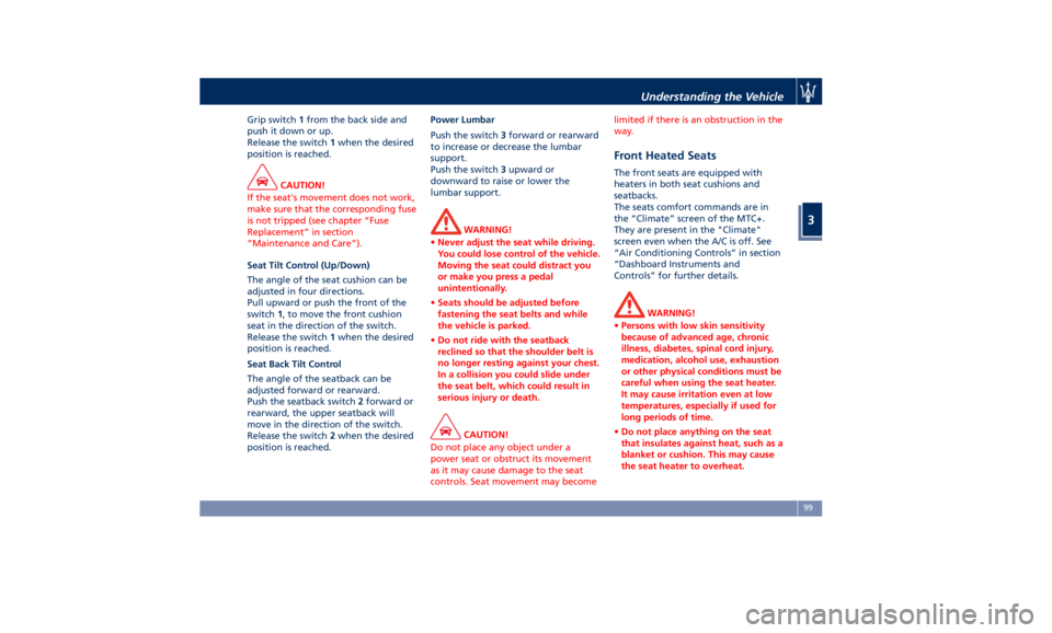
Grip switch 1 from the back side and
push it down or up.
Release the switch 1 when the desired
position is reached.
CAUTION!
If the seat's movement does not work,
make sure that the corresponding fuse
is not tripped (see chapter “Fuse
Replacement” in section
“Maintenance and Care”).
Seat Tilt Control (Up/Down)
The
angle of the seat cushion can be
adjusted in four directions.
Pull upward or push the front of the
switch 1 , to move the front cushion
seat in the direction of the switch.
Release the switch 1 when the desired
position is reached.
Seat Back Tilt Control
The angle of the seatback can be
adjusted forward or rearward.
Push the seatback switch 2 forward or
rearward, the upper seatback will
move in the direction of the switch.
Release the switch 2 when the desired
position is reached. Power Lumbar
Push the switch 3 forward or rearward
to increase or decrease the lumbar
support.
Push the switch 3 upward or
downward to raise or lower the
lumbar support.
WARNING!
• Never adjust the seat while driving.
You could lose control of the vehicle.
Moving the seat could distract you
or make you press a pedal
unintentionally.
• Seats should be adjusted before
fastening the seat belts and while
the vehicle is parked.
• Do not ride with the seatback
reclined so that the shoulder belt is
no longer resting against your chest.
In a collision you could slide under
the seat belt, which could result in
serious injury or death.
CAUTION!
Do not place any object under a
power seat or obstruct its movement
as it may cause damage to the seat
controls. Seat movement may become limited if there is an obstruction in the
way.
Front Heated Seats The front seats are equipped with
heaters in both seat cushions and
seatbacks.
The seats comfort commands are in
the “Climate” screen of the MTC+.
They are present in the "Climate"
screen even when the A/C is off. See
“Air Conditioning Controls” in section
“Dashboard Instruments and
Controls” for further details.
WARNING!
• Persons with low skin sensitivity
because of advanced age, chronic
illness, diabetes, spinal cord injury,
medication, alcohol use, exhaustion
or other physical conditions must be
careful when using the seat heater.
It may cause irritation even at low
temperatures, especially if used for
long periods of time.
• Do not place anything on the seat
that insulates against heat, such as a
blanket or cushion. This may cause
the seat heater to overheat.Understanding the Vehicle
3
99
Page 110 of 396
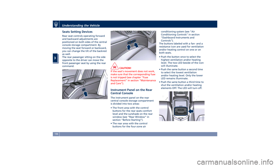
Seats Setting Devices Rear seat controls operating forward
and backward adjustments are
positioned on both sides of the central
console storage compartment. By
moving the seat forward or backward,
you can change the tilt of the backrest
as well.
The rear passenger sitting on the side
opposite to the driver can move the
front passenger seat by using the rear
command.
CAUTION!
If the seat's movement does not work,
make sure that the corresponding fuse
is not tripped (see chapter “Fuse
Replacement” in section “Maintenance
and Care”).
Instrument Panel on the Rear
Central Console The instrument panel on the rear
central console storage compartment
is divided into two areas:
• The front area with the control
buttons for the rear seats comfort
level and the sunshade on the rear
window (see “Rear Window” in
section “Before Starting”).
• The rear area with the control
buttons for the four-zone air conditioning system (see “Air
Conditioning Controls” in section
“Dashboard Instruments and
Controls”).
The buttons labeled with a fan- and a
resistance icon are used for ventilation
and/or heating control on one or on
both seats.
• Push the button once to select the
highest ventilation and/or heating
level. The two LED beside of the icon
will illuminate.
• Push the same button a second time
to select the lowest ventilation
and/or heating level. Only the lower
LED remains illuminate.
• Push the same button a third time to
shut the ventilation and/or heating
elements OFF. The LED will turn off.Understanding the Vehicle
3
106
Page 134 of 396
(Continued)
servicing your vehicle. For more
information go to:
www.P65Warnings.ca.gov/passenger-
vehicle
Heated Windshield Washer Nozzles
T
o avoid fluid freezing inside at low
external temperatures, the fluid supply
nozzles can be heated by internal
resistors.
Interior Features Electric Power Outlets The vehicle is equipped with four 12
Volt (13 Amp) electric power outlets,
two available for the front seat
passengers, one for rear seat
passengers and one fitted in the trunk
compartment.
In vehicles equipped with “Smoking
Kit” the electric power outlet inside
the cupholder is replaced with a
cigarette lighter.
All power outlets are supplied only
when the engine is started or the
ignition device set to ACC or RUN .
Power outlets are protected by a fuse.
Insert a cigar lighter or accessory plug
into the power outlets to ensure
proper operation. Otherwise, check
the matching fuse integrity, see “Fuse
Replacement” in section “Maintenance
and Care” for further information.
CAUTION!
• Do not plug in accessories that
exceed the maximum power of 160
Watts (13 Amps) at 12 Volts.
• Power outlets are designed for
accessory plugs only. Do not insert
any other object in the power outlets as this will damage the outlet and
blow the fuse. Damages caused by
improper use of the power outlet are
not covered by the New Vehicle
Limited Warranty.
WARNING!
To avoid serious injury or death:
• Only devices designed for use in this
type of outlet should be inserted
into any 12 Volt outlet.
• Replacing the fuses that protect
power outlets with others of higher
amperage, there is the risk of fire.
• Do not touch with wet hands.
• Close the lids when the plug is not
used and while driving the vehicle.
• If this outlet is mishandled, it may
cause an electric shock and failure.
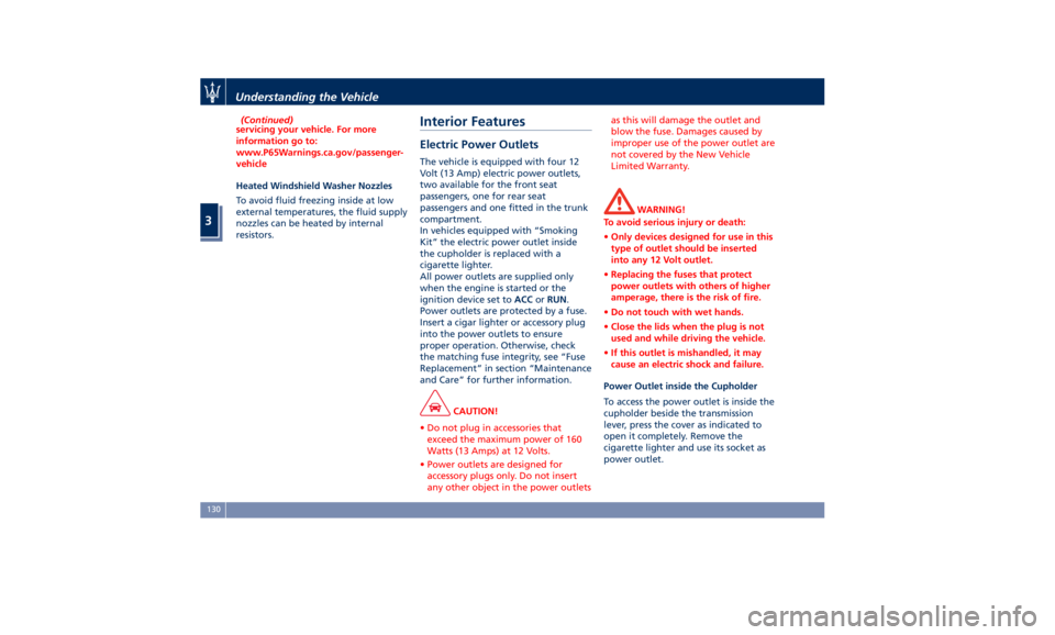
Power Outlet inside the Cupholder
To access the power outlet is inside the
cupholder beside the transmission
lever, press the cover as indicated to
open it completely. Remove the
cigarette lighter and use its socket as
power outlet.Understanding the Vehicle
3
130
Page 331 of 396
7 – Maintenance and Care Scheduled Maintenance Service ............................ 328
Scheduled Service Plan ................................... 329
Maintenance Procedures ................................. 334
Maintenance-Free Battery ................................ 344
Fuse Replacement ...................................... 348
Bulb Replacement ...................................... 355
A/C System Maintenance ................................. 357
Wheels Maintenance .................................... 358
Bodywork Maintenance and Care .......................... 360
Interior Maintenance and Care ............................ 363
Vehicle Stored for Long Periods ............................ 364
Restarting the Vehicle ................................... 365
Battery Statement ...................................... 366
327
Page 339 of 396
Maintenance Service
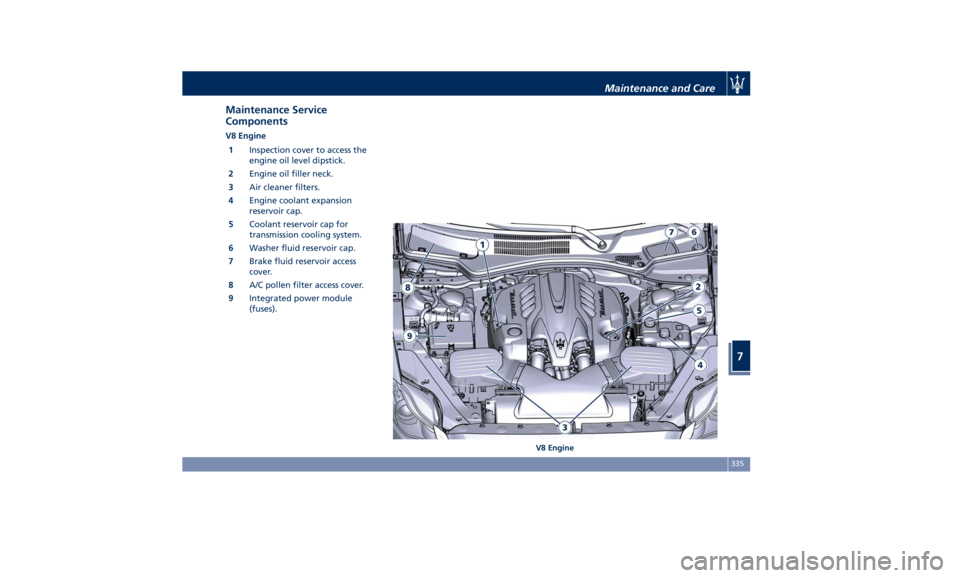
Components V8 Engine
1 Inspection cover to access the
engine oil level dipstick.
2 Engine oil filler neck.
3 Air cleaner filters.
4 Engine coolant expansion
reservoir cap.
5 Coolant reservoir cap for
transmission cooling system.
6 Washer fluid reservoir cap.
7 Brake fluid reservoir access
cover.
8 A/C pollen filter access cover.
9 Integrated power module
(fuses).
V8 EngineMaintenance and Care
7
335
Page 340 of 396
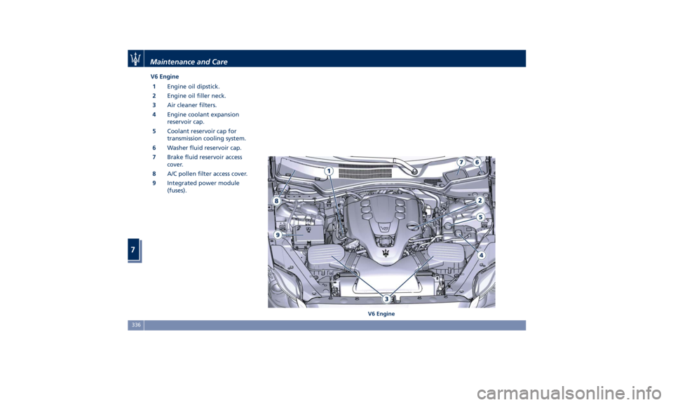
V6 Engine
1 Engine oil dipstick.
2 Engine oil filler neck.
3 Air cleaner filters.
4 Engine coolant expansion
reservoir cap.
5 Coolant reservoir cap for
transmission cooling system.
6 Washer fluid reservoir cap.
7 Brake fluid reservoir access
cover.
8 A/C pollen filter access cover.
9 Integrated power module
(fuses).
V6 EngineMaintenance and Care
7
336
Page 352 of 396
• Turn the charger on and follow the
instructions on its user manual to
completely recharge the battery.
• When the battery is recharged, turn
off the battery charger before
disconnecting it from the battery.
• Disconnect first the terminal clamp
of the charger black cable from the
battery and then the terminal clamp
of the red cable.
• Reassemble the protection cover on
the battery positive post and the
other parts removed for this
operation.
WARNING!
California Proposition 65
Operating, servicing and maintaining
a passenger vehicle or off-road vehicle
can expose you to chemicals including
such as, engine exhaust, carbon
monoxide, phthalates and lead, that
which are known to the State of
California to cause cancer and birth
defects or other reproductive harm. To
minimize exposure, avoid breathing
exhaust, do not idle the engine except
as necessary, service your vehicle in a
well-ventilated area and wear gloves
or wash your hands frequently when
servicing your vehicle. For more information go to:
www.P65Warnings.ca.gov/passenger-
vehicle
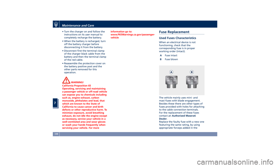
Fuse Replacement Used Fuses Characteristics When an electrical device is not
functioning, check that the
corresponding fuse is in proper
working order (intact).
A Fuse intact
B Fuse blown
The vehicle mainly uses mini- and
maxi-fuses with blade engagement.
Besides these there are other types of
fuses provided with holes for attaching
to the cable connection terminals.
For the replacement of these fuses
contact an Authorized Maserati
Dealer .
Replace the faulty fuse with a new one
featuring the same rating, by using
appropriate forceps added in theMaintenance and Care
7
348