2019 MASERATI LEVANTE Fuel
[x] Cancel search: FuelPage 342 of 436

Fuel Filler Cap Open Warning
Light After refueling the car
performs a check of the fuel
filler cap and the amber
warning light on the TFT
display comes on if it is not correctly
closed, after approximately 10 minutes
also depending on driving conditions.
If the problem is in the fuel system, the
Malfunction Indicator Light
also
comes on.
If the fuel filler cap is locked and the
issue remains in the system, at the next
engine start only the Malfunction
Indicator Light
comes on. In this
case, contact an Authorized Maserati
Dealer .
Emergency Fuel Filler Door
Release If you are unable to unlock the fuel
filler door using the key fob RKE
transmitter, use the fuel filler door
emergency release located in the
trunk.
• Open the power liftgate (see “Power
Liftgate Operation” in section
“Before Starting”).
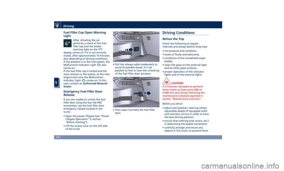
• Lift the access cover on the left side
of the trunk. • Pull the release cable moderately to
avoid its possible break. It's not
possible to feel or hear the unlocking
of the fuel filler door actuator.
• Then open normally the fuel filler
door.Driving Conditions Before the Trip Check the following at regular
intervals and always before long trips:
• tire pressure and condition;
• levels of fluids and lubricants;
• conditions of the windshield wiper
blades;
• clean the glass on the external light
and all other glass surfaces;
• proper operation of the indicator
lights and of the external lights.
CAUTION!
It is however advisable to perform
these checks at least every 600 mi
(1000 km) and always following the
maintenance schedule reported in
section “Maintenance and Care”.
Before you drive:
•
adjust seat position, steering wheel,
adjustable pedals (if equipped with)
and rearview mirrors in order to have
the best driving position;
• ensure that nothing (mat covers, etc.)
is obstructing the pedals movement;
• carefully arrange and secure any
objects in the trunk, to prevent themDriving
5
338
Page 354 of 436

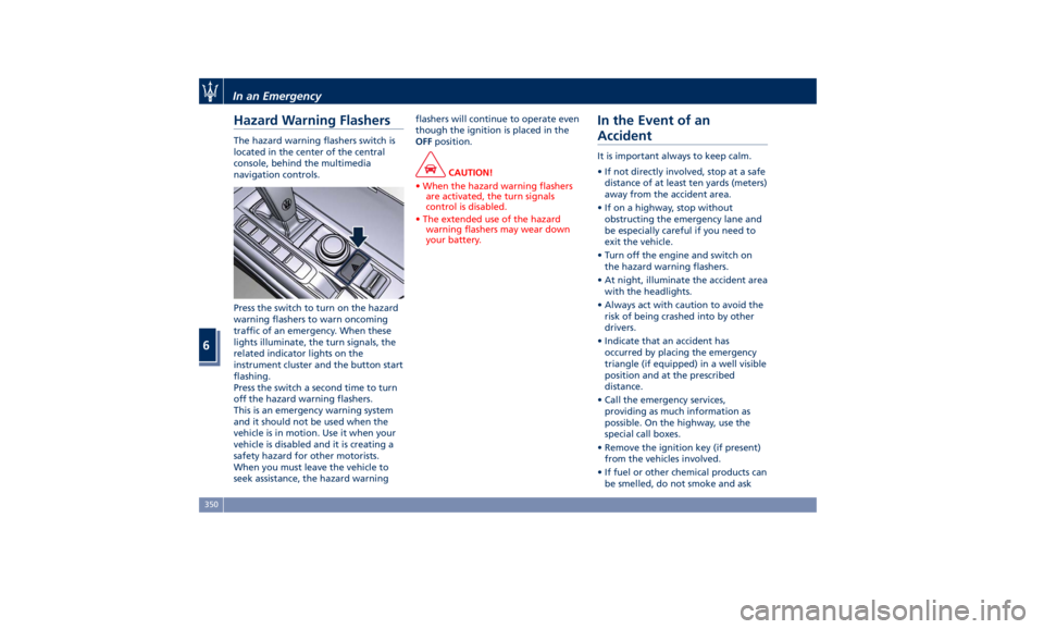
Hazard Warning Flashers The hazard warning flashers switch is
located in the center of the central
console, behind the multimedia
navigation controls.
Press the switch to turn on the hazard
warning flashers to warn oncoming
traffic of an emergency. When these
lights illuminate, the turn signals, the
related indicator lights on the
instrument cluster and the button start
flashing.
Press the switch a second time to turn
off the hazard warning flashers.
This is an emergency warning system
and it should not be used when the
vehicle is in motion. Use it when your
vehicle is disabled and it is creating a
safety hazard for other motorists.
When you must leave the vehicle to
seek assistance, the hazard warning flashers will continue to operate even
though the ignition is placed in the
OFF position.
CAUTION!
• When the hazard warning flashers
are activated, the turn signals
control is disabled.
• The extended use of the hazard
warning flashers may wear down
your battery.
In the Event of an
Accident It is important always to keep calm.
• If not directly involved, stop at a safe
distance of at least ten yards (meters)
away from the accident area.
• If on a highway, stop without
obstructing the emergency lane and
be especially careful if you need to
exit the vehicle.
• Turn off the engine and switch on
the hazard warning flashers.
• At night, illuminate the accident area
with the headlights.
• Always act with caution to avoid the
risk of being crashed into by other
drivers.
• Indicate that an accident has
occurred by placing the emergency
triangle (if equipped) in a well visible
position and at the prescribed
distance.
• Call the emergency services,
providing as much information as
possible. On the highway, use the
special call boxes.
• Remove the ignition key (if present)
from the vehicles involved.
• If fuel or other chemical products can
be smelled, do not smoke and askIn an Emergency
6
350
Page 361 of 436

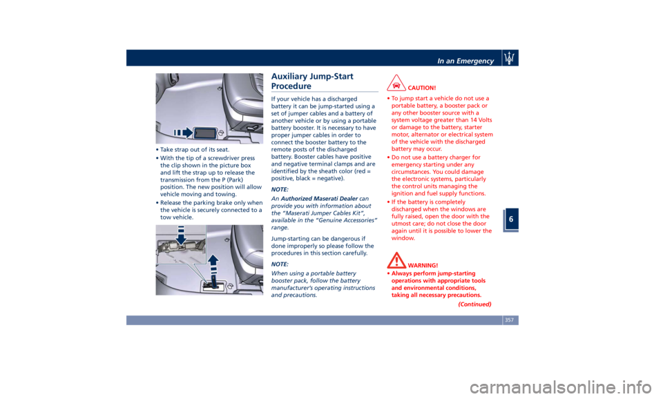
• Take strap out of its seat.
• With the tip of a screwdriver press
the clip shown in the picture box
and lift the strap up to release the
transmission from the P (Park)
position. The new position will allow
vehicle moving and towing.
• Release the parking brake only when
the vehicle is securely connected to a
tow vehicle. Auxiliary Jump-Start
Procedure If your vehicle has a discharged
battery it can be jump-started using a
set of jumper cables and a battery of
another vehicle or by using a portable
battery booster. It is necessary to have
proper jumper cables in order to
connect the booster battery to the
remote posts of the discharged
battery. Booster cables have positive
and negative terminal clamps and are
identified by the sheath color (red =
positive, black = negative).
NOTE:
An Authorized Maserati Dealer can
provide you with information about
the “Maserati Jumper Cables Kit”,
available in the “Genuine Accessories”
range.
Jump-starting can be dangerous if
done improperly so please follow the
procedures in this section carefully.
NOTE:
When using a portable battery
booster pack, follow the battery
manufacturer’s operating instructions
and precautions. CAUTION!
• To jump start a vehicle do not use a
portable battery, a booster pack or
any other booster source with a
system voltage greater than 14 Volts
or damage to the battery, starter
motor, alternator or electrical system
of the vehicle with the discharged
battery may occur.
• Do not use a battery charger for
emergency starting under any
circumstances. You could damage
the electronic systems, particularly
the control units managing the
ignition and fuel supply functions.
• If the battery is completely
discharged when the windows are
fully raised, open the door with the
utmost care; do not close the door
again until it is possible to lower the
window.
WARNING!
• Always perform jump-starting
operations with appropriate tools
and environmental conditions,
taking all necessary precautions.
(Continued)In an Emergency
6
357
Page 372 of 436

(Continued)
defects or other reproductive harm. To
minimize exposure, avoid breathing
exhaust, do not idle the engine except
as necessary, service your vehicle in a
well-ventilated area and wear gloves
or wash your hands frequently when
servicing your vehicle. For more
information go to:
www.P65Warnings.ca.gov/passenger-
vehicle
Heavy-Duty Vehicle Use If the car is mainly used under one of
the following conditions:
• towing a trailer;
• off-road;
• short, repeated journeys (less than
4–5 mi/7-8 km) at sub-zero outside
temperatures;
• engine often idling or driving long
distances at low speeds or long
periods of idleness;
you should perform the following
inspections more frequently than
recommended on the “Scheduled
Service Plan”:
• check front disc brake pad conditions
and wear; • check cleanliness of hood and trunk
locks, cleanliness and lubrication of
linkage;
• visually inspect conditions of: engine,
transmission, pipes and hoses
(exhaust - fuel system - brakes) and
rubber elements (boots - sleeves -
bushes - etc.);
• check battery charge;
• visually inspect condition of the
accessory drive belts;
• check and, if necessary, change
engine oil and replace oil filter;
• check and, if necessary, replace
pollen filter of the A/C system;
• check and, if necessary, replace air
cleaner filter.
CAUTION!
All maintenance operations for the
vehicle must be carried out by an
Authorized Maserati Dealer . For
routine and minor maintenance
operations which you can carry out
yourself, make sure that you have the
necessary experience and always use
suitable equipment, original Maserati
spare parts and the prescribed fluids.
Shall this not be the case, do not carry
any operation on your own and
contact an Authorized Maserati Dealer .
On Board Diagnostic System Your vehicle is equipped with a
sophisticated on board diagnostic
system called OBD II. This system
monitors the performance of the
emissions, engine, and automatic
transmission control systems. When
these systems are operating properly,
your vehicle will provide excellent
performance and fuel economy, as
well as engine emissions suited to
current government regulations.
If any of these systems require service,
the OBD II system will turn on the
Malfunction Indicator Light
on the
instrument cluster display (refer to
“Instrument Cluster” in section
“Dashboard Instruments and
Controls”). The system stores as well
diagnostic codes and other
information to assist your service
technician by performing repairs.
Although the vehicle will be driveable
and will not need towing, contact an
Authorized Maserati Dealer for service
as soon as possible.Maintenance and Care
7
368
Page 373 of 436

CAUTION!
• Prolonged driving with the MIL
on could cause further damage to
the emissions control system. It could
also affect fuel economy and
driveability. The vehicle must be
serviced before any emissions tests
can be performed.
• If the MIL
is flashing while the
engine is running, severe catalytic
converter damage and power loss
will soon occur. Immediate service at
an Authorized Maserati Dealer is
required. Emissions Inspection and
Maintenance Programs In some localities, it may be a legal
requirement to pass an inspection of
your vehicle's emissions control
system. Failure to pass could prevent
vehicle registration. For states that
require an Inspection and
Maintenance (I/M), this check verifies
the “Malfunction Indicator Light
”
is functioning and is not on when the
engine is running, and that the OBD II
system is ready for testing.
Normally, the OBD II system will be
ready. The OBD II system may not be
ready if your vehicle was recently
serviced, recently had a dead battery
or a battery replacement. If the OBD II
system should be determined not
ready for the I/M test, your vehicle
may fail the test.
To check if your vehicle's OBD II system
is ready, you must do the following: 1. Press the ignition device to the
RUN position, but do not crank or
start the engine.
2. As soon as you press the ignition
device to turn the engine On, you
will see the MIL remain
illuminated for 15 seconds, this is a
normal bulb check.
3. Approximately 15 seconds later,
one of two things will happen:
•
The MIL
will remain
illuminated and a message error
will appear on your instrument
cluster. This means that your
vehicle's OBD II system is not
ready and you should not
proceed to the I/M station.
•
The MIL
will turn Off. This
means that your vehicle's OBD II
system is ready and you can
proceed to the I/M station.
If your OBD II system is not ready, you
should see an Authorized Maserati
Dealer or repair facility. If your vehicle
was recently serviced or had a battery
failure or replacement, you may need
to do nothing more than drive your
vehicle as you normally would in order
for your OBD II system to update. A
recheck with the above test routineMaintenance and Care
7
369
Page 393 of 436

Ref. Type Function
39 Mini – 7,5A Flow meters,
tank lackage,
canister, exhaust
by-pass valve
relay coil and air
shutter
48 – –
49 Mini – 10A Pedal brake
switch-TCM
module
50 Mini – 15A +30 PCM module
51 Mini – 30A Fuel pump relay
input
52 Mini – 5A Starter solenoid
signal for PCM
and voltage
stabilizer
53 Mini – 10A AWD module
Rear Power Distribution Center • To access the center it is necessary to
lift the ground coverage of the trunk
compartment (see chapter “Tool Kit”
in section “In an Emergency”) and
remove the storage box.
• To access the fuses, release the cover
latch shown in picture. • Press the release latch and lift the lid
from this side.
• Push the lid toward the right side to
release the indicated latches on the
unit.
The table points out the position as
featured in the figure, the type and
function of the fuses on the rear area
distribution control unit. Ref. Type Function
2 Maxi – 40A BCM module
3 Maxi – 40A BCM module
4 Maxi – 30A BCM module
5 Maxi – 30A BCM module
6 Maxi – 20A Trailer harness
(not for TROFEO
version)
7 Maxi – 30A Driver door
module
8 Maxi – 30A Passenger door
module
9 Maxi – 40A Start&Stop:
voltage
stabilizer,
dashboard
10 Maxi – 40A Start&Stop:
voltage
stabilizer, body
11 Maxi – 40A “High Premium”
stereo amplifier
unit
Maxi – 20A “Premium”
stereo amplifier
unit (1)
15 Maxi – 40A HVAC front
blower relay coilMaintenance and Care
7
389
Page 394 of 436

Ref. Type Function
16 Maxi – 40A Rear window
defrost relay coil
(HVAC module)
17 Maxi – 30A Rear LH door
module
18 Maxi – 30A Rear RH door
module Ref. Type Function
19 Maxi – 25A Power liftgate
module
20 Maxi – 20A “Premium”
stereo amplifier
unit (2)
21 Maxi – 40A ELDOR coil (V8
engines only) Ref. Type Function
22 Mini – 7,5A Rear HVAC
module
23 Mini – 10A Fuel door relay
and RF Hub
module
24 Mini – 10A ITM module,
ceiling light unit
(front and rear),
rain/lights sensor
25 Mini – 25A Sunroof module
26 – –
27 – –
31 Mini – 30A LH front seat
movement
32 Mini – 15A Trailer module
LH side (not for
TROFEO version)
33 Mini – 15A Trailer module
RH side (not for
TROFEO version)
34 Mini – 20A Soft Door Close
latch
35 Mini – 20A Rear doors
sunshadeMaintenance and Care
7
390
Page 409 of 436

8 – Features and Specifications Refillings ............................................. 406
Fuel Consumption ...................................... 410
Technical Data ......................................... 411
Tire Inflation Pressure ................................... 420
405