2019 MASERATI LEVANTE turn signal
[x] Cancel search: turn signalPage 322 of 436
• Press the HAS enable button on
the steering wheel.
• Begin steering manually.
• Press brake pedal.
• Turn off ACC.
• Unbuckle the driver’s seat belt.
• Press ACC Gap button for two
seconds to enable CC system.
• Shift out of the (D) Drive gear.
• Enter an Autonomous Emergency
Braking (AEB) event (See chapter
"Forward Collision Warning - FCW"
in this section).
• Turn signal activated.
System Cancellation The HAS system will cancel (without
driver intervention) if either of the
following actions occur:
• Curve that is too tight.
• When leaving the grip of the hands
on the steering wheel.
• Vehicle exits the highway or limited
access freeway.
• Lane line markers aren’t detected by
the forward facing camera.
• Any ADAS system faults.
• ACC cancellation.
• Vehicle speed exceeds the maximum
limit. • Lateral accelerations exceeds the
limits.
NOTE:
• When HAS cancels, the
symbol
will turn red then grey.
• The presence of the hands on the
steering wheel is detected by a logic
combination of a capacitive sensor
installed in the steering wheel and
the measured applied torque at the
steering column. This leads to a more
robust hands detection.
System Limitations HAS is unable to guide the vehicle
when the following conditions occur.
• Lane markings are not clear or
visibility is poor (i.e. heavy rain,
snow, fog, etc.).
• Obstructed, covered or damaged
forward-facing camera or sensor.
• When driving on hills or sharp curves.
• When approaching toll booths.
• When the highway entrance or exit is
wider than 20 ft (6 meters).
• Bright light (ex. direct sunlight or
glare) facing the forward camera. WARNING!
Many unforeseen conditions can occur
that can affect the performance of
Highway Assist (HAS). Always keep
this in mind and drive attentively. It is
the drivers responsibility to keep
control of the vehicle at all times.
Radar Device - Regulatory
Information The “Regulatory Information” for all
the radio frequency and radar devices
can be consulted by accessing the
"Services" section on the website
www.maserati.com.Driving
5
318
Page 335 of 436

will monitor the actual tire pressure
in the tire.
Premium System The TPMS system uses wireless
technology with wheel rim mounted
electronic sensors to monitor tire
pressure levels. Sensors mounted to
each wheel as part of the valve stem
transmit tire pressure readings to the
receiver module.
The TPMS consists of the following
components:
• receiver module;
• four TPMS sensors;
• various TPMS messages, which
display on the instrument cluster;
• warning light
.
Tire Pressure Low Warning
The TPMS light will illuminate in
the instrument cluster and an acoustic
signal will notify that tire pressure is
low in one or more of the four tires. The instrument cluster will also display
a screenshot reporting the pressure
values of each tire with flashing low
pressure value.
Should this occur, you should stop as
soon as possible and inflate the tire/s
with the low pressure (the one/s
flashing in the instrument cluster
graphic) to the recommended cold
pressure inflation value. Once the
system receives the updated tire
pressure value, the system will automatically update, the graphic
display in the instrument cluster will
stop flashing, and the TPMS light
will turn off. The vehicle may need
to be driven for up to 20 minutes
above 15 mph (24 km/h) in order for
the TPMS to acquire and process the
updated information.
Tire Pressure System Fault
If a system fault is detected, the TPMS
light
will flash for 75 seconds and
then remain lit followed by a beeping
sound. Therewith, the instrument
cluster will display a "Service Tire
Pressure System" message for a
minimum of five seconds and then
display dashes (--) in place of the
pressure value to indicate which
sensor is ineffective.
If the ignition switch is cycled, the
sequence will repeat, in case the
system fault still persists. If the system
fault no longer exists, the TPMS light
will no longer flash, and the
"Service Tire Pressure System"
message will no longer be displayed,
and a pressure value will be displayed
in place of the dashes.
A system fault can occur due to any of
the following:
• Signal interference due to electronic
devices or driving next to facilitiesDriving
5
331
Page 346 of 436

For pressure of trailer tires, follow the
instructions given by the trailer
manufacturer.
After adjusting vehicle tire pressure
and connecting and disconnecting the
trailer, initialize the Tire Pressure
Monitoring System (TPMS) following
the instructions under chapter “Tire
Pressure Monitoring System (TPMS)” in
this section.
Field of Vision of External
Rearview Mirrors Law provisions require the field of
vision of external rearview mirrors to
include the rear trailer corners.
If vehicle external rearview mirrors
cannot cover the required field of
vision, it is possible to install additional
rearview mirrors sticking further out at
the sides.
The Authorized Maserati Dealer can
provide you with information about
towing a trailer and about the
approved components available in the
"Genuine Accessories" range. Trailer Lights Law provisions require trailers to be
equipped with an electrical lighting
system that must include the following
lights:
• Turn signals;
• Position lights;
• Stop lights;
• Rear fog lights;
• Reverse lights;
• License plate lights;
• Side marker lights (for trailer width
over 6.8 ft/2.1 m).
The power input of the trailer lights
must not exceed the values in the
following list.
• Position lights, side marker lights and
license plate lights :6x5Wper side.
• Rear fog lights :2x21W
• Turn signals :2x21W
• Stop lights :4x21W
• Reverse lights :2x21W
Minimum detectable current of Trailer
Tow Module (TTM): 100mA. Trailer Wiring Harness
Vehicle trailer tongue includes a 4-pin
sealed connector powered at 12VDC
for connection of the corresponding
trailer wiring connector.
In addition to the electrical branches,
the vehicle electrical system can only
be connected to the supply cable for
an electric brake and to the cable for
an internal light for the trailer, not
exceeding 15W.
CAUTION!
Do not cut or splice wiring into the
vehicle wiring harness. Do not change
cable connections on connectors. TheDriving
5
342
Page 347 of 436
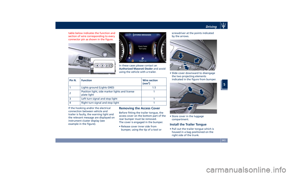
table below indicates the function and
section of wire corresponding to every
connector pin as shown in the figure.
If the hooking and/or the electrical
connection between vehicle and
trailer is faulty, the warning light and
the relevant message are displayed on
instrument cluster display (see
example in the figure). In these cases please contact an
Authorized Maserati Dealer and avoid
using the vehicle with a trailer.
Removing the Access Cover Before fitting the trailer tongue, the
access cover on the bottom part of the
rear bumper must be removed.
The cover is engaged in the bumper.
• Release cover inner side from
bumper, using the tip of a tool or screwdriver at the points indicated
by the arrows.
• Slide cover downward to disengage
the two projecting elements
indicated in the figure from bumper.
• Store cover in the luggage
compartment.
Install the Trailer Tongue • Pull out the trailer tongue which is
housed in a bag positioned on the
right side of the trunk.Pin N. Function Wire section
(mm 2
)
1 Lights ground (Lights GND) 1.5
2 Position light, side marker lights and license
plate light 1
3 Left turn signal and stop light 1
4 Right turn signal and stop light 1 Driving
5
343
Page 354 of 436
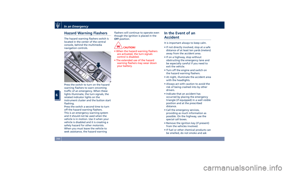
Hazard Warning Flashers The hazard warning flashers switch is
located in the center of the central
console, behind the multimedia
navigation controls.
Press the switch to turn on the hazard
warning flashers to warn oncoming
traffic of an emergency. When these
lights illuminate, the turn signals, the
related indicator lights on the
instrument cluster and the button start
flashing.
Press the switch a second time to turn
off the hazard warning flashers.
This is an emergency warning system
and it should not be used when the
vehicle is in motion. Use it when your
vehicle is disabled and it is creating a
safety hazard for other motorists.
When you must leave the vehicle to
seek assistance, the hazard warning flashers will continue to operate even
though the ignition is placed in the
OFF position.
CAUTION!
• When the hazard warning flashers
are activated, the turn signals
control is disabled.
• The extended use of the hazard
warning flashers may wear down
your battery.
In the Event of an
Accident It is important always to keep calm.
• If not directly involved, stop at a safe
distance of at least ten yards (meters)
away from the accident area.
• If on a highway, stop without
obstructing the emergency lane and
be especially careful if you need to
exit the vehicle.
• Turn off the engine and switch on
the hazard warning flashers.
• At night, illuminate the accident area
with the headlights.
• Always act with caution to avoid the
risk of being crashed into by other
drivers.
• Indicate that an accident has
occurred by placing the emergency
triangle (if equipped) in a well visible
position and at the prescribed
distance.
• Call the emergency services,
providing as much information as
possible. On the highway, use the
special call boxes.
• Remove the ignition key (if present)
from the vehicles involved.
• If fuel or other chemical products can
be smelled, do not smoke and askIn an Emergency
6
350
Page 397 of 436
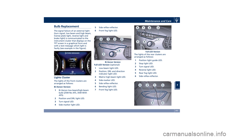
Bulb Replacement The signal failure of an external light
(turn signal, low beam and high beam,
license plate light, reverse light and
brake light) is communicated to the
instrument cluster that displays on the
TFT screen in a graphical form and
with a text message which light is
faulty (see example in the figure).
Lights Cluster The lights of the front clusters are
arranged as follows:
Bi-Xenon Version
1 Bi-Xenon low-beam/high-beam
bulb (25W-No AFS, 35W-With
AFS).
2 Position and DRL light LED.
3 Turn signal LED.
4 Side-marker light LED. 5 Side reflex-reflector.
6 Front fog light LED.
Full-LED Version (optional)
1 Low-beam light LED.
2 Position, DRL and direction
indicator light LED.
3 Matrix high-beam light LED.
4 Side-marker LED.
5 Side reflex-reflector.
6 Bending light LED.
7 Front fog light LED. The lights of the rear clusters are
arranged as follows:
1 Position light guide LED.
2 Stop light LED.
3 Turn signal LED.
4 Reverse light LED.
5 Rear fog light LED.
6 Side reflex-reflector.Bi-Xenon Version Full-LED VersionMaintenance and Care
7
393
Page 430 of 436
Handholds and Cloth Hooks . . . .138
Hazard Warning Flashers ....... .350
Head Restraints ...............98
Highway Assist - HAS ......... .313
Hill Descend Control (HDC) ..... .277
HomeLink ................. .150
Security ................. .153
Troubleshooting Tips ........ .153
Using HomeLink ........... .153
Hood
Open and Close the Hood ......56
Hood Operation ..............56
HSA (Hill Start Assist) ......... .276
Identification Labels ............19
Illuminated Entry/Exit ...........30
Immobilizer (Sentry Key) .........26
Indicator Lights/Warning Lights
Air Bag Warning Light .........90
TFT Display: Menus and Settings .165
TFT Display: Warning/Indicator
Lights of Set Modes/Functions. . .178
Warning and Indicator Lights on
Analog Instrument ......... .161
Infotainment System .......... .185
Main Menu Bar on MTC+
Display ................. .187
Manual Controls and Devices . . .186
Personalized the Main Menu Bar.188
Instrument Cluster ........... .160
Interior Components ...........94
Interior Maintenance and Care. . . .400 Interiors Features ............ .133
iPad Holder ................ .139
iPod Connection ............. .136
Jump Start Procedure ......... .358
KeyFob ....................25
Key fob Battery Replacement ....35
Preventing Inadvertent Locking of
key fob RKE Transmitter Inside the
Vehicle ...................43
Replacement ...............27
Requiring and setting Additional
Key Fobs ..................34
Unlock the Vehicle with Key fob . .33
Keys .......................24
Lane Departure Warning (LDW) . . .301
Level Checks ............... .374
Brake Fluid Level Check ...... .375
Engine Coolant Level Check . . . .374
Engine Oil Level Check ....... .374
Fluid Level Check for Coolant
Transmission System ........ .379
Transmission Oil Check ....... .378
Washer/Headlight Fluid, adding .376
Liftgate
Automatic
Opening and Closing
Movement
of the Power Liftgate .51
Liftgate and Hood Ajar
Indicators ................ .180
Power Liftgate Emergency
Release ...................55 Power Liftgate Operation ......50
Unlatch the Liftgate ..........34
Lights .................... .113
Automatic Headlights ....... .115
Automatic Headlights Leveling . .126
Automatic High Beam ....... .120
Bi-Xenon Headlight ......... .117
Bulb Replacement .......... .393
Cargo Lamps ............. .127
Dome Lights .............. .126
DRL, Daytime Running Lights . . .116
Fog Lights ............... .123
Headlight Time Delay ....... .115
Headlight with AFS ......... .117
High Beam and Flashing ..... .124
Interior Lights ............. .125
Light Switch .............. .113
Multifunction Lever ......... .124
SmartBeam System ......... .116
Turn Signals .............. .124
Loading the Vehicle
Loading with Rear Seatbacks
Down .................. .141
Vehicle Load Carrying Capacity . .139
Main- and Submenu .......... .166
Maintenance ..................5
A/C System Maintenance ..... .395
Air Bag System Maintenance ....72
Bodywork Maintenance and
Care ................... .397
Emissions Inspection and
Maintenance Programs ...... .369Index
9 426