2019 MASERATI LEVANTE ABS
[x] Cancel search: ABSPage 357 of 436

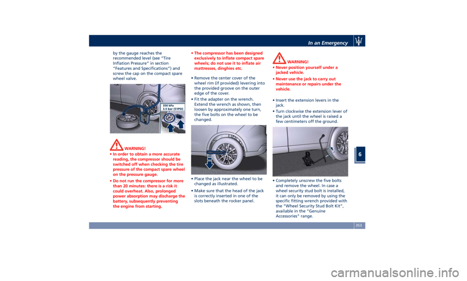
by the gauge reaches the
recommended level (see “Tire
Inflation Pressure” in section
“Features and Specifications”) and
screw the cap on the compact spare
wheel valve.
WARNING!
• In order to obtain a more accurate
reading, the compressor should be
switched off when checking the tire
pressure of the compact spare wheel
on the pressure gauge.
• Do not run the compressor for more
than 20 minutes: there is a risk it
could overheat. Also, prolonged
power absorption may discharge the
battery, subsequently preventing
the engine from starting. • The compressor has been designed
exclusively to inflate compact spare
wheels; do not use it to inflate air
mattresses, dinghies etc.
• Remove the center cover of the
wheel
rim (if provided) levering into
the provided groove on the outer
edge of the cover.
• Fit the adapter on the wrench.
Extend the wrench as shown, then
loosen by approximately one turn,
the five bolts on the wheel to be
changed.
• Place the jack near the wheel to be
changed as illustrated.
• Make sure that the head of the jack
is correctly inserted in one of the
slots beneath the rocker panel. WARNING!
• Never position yourself under a
jacked vehicle.
• Never use the jack to carry out
maintenance or repairs under the
vehicle.
• Insert the extension levers in the
jack.
•
Turn clockwise
the extension lever of
the jack until the wheel is raised a
few centimeters off the ground.
• Completely unscrew the five bolts
and remove the wheel. In case a
wheel security stud bolt is installed,
it can only be removed by using the
specific fitting wrench provided with
the “Wheel Security Stud Bolt Kit”,
available in the “Genuine
Accessories” range.In an Emergency
6
353
Page 359 of 436

will be compromised. Avoid
accelerating to full speed, heavy
braking and fast cornering.
• The compact spare wheel must be
inflated to the recommended tire
pressure (see “Tire Inflation
Pressure” in section “Features and
Specifications”).
• For safety reasons, it is absolutely
forbidden to drive with more than
one compact spare wheel fitted on
the vehicle.
• Snow chains cannot be fitted on the
compact spare wheel.
• The spare wheel can travel a
maximum of 1,800 mi (3.000 km).
To Refit the Standard Wheel with
Repair
ed or Replaced Tire
• Following the procedure and the
caution described above, raise the
vehicle and remove the compact
spare wheel reusing the supplied
wrench with adapter, suitably
extended.
• Fit the standard wheel with repaired
or replaced tire.
• Tighten the original bolts on the
wheel.
• Lower the vehicle and remove the
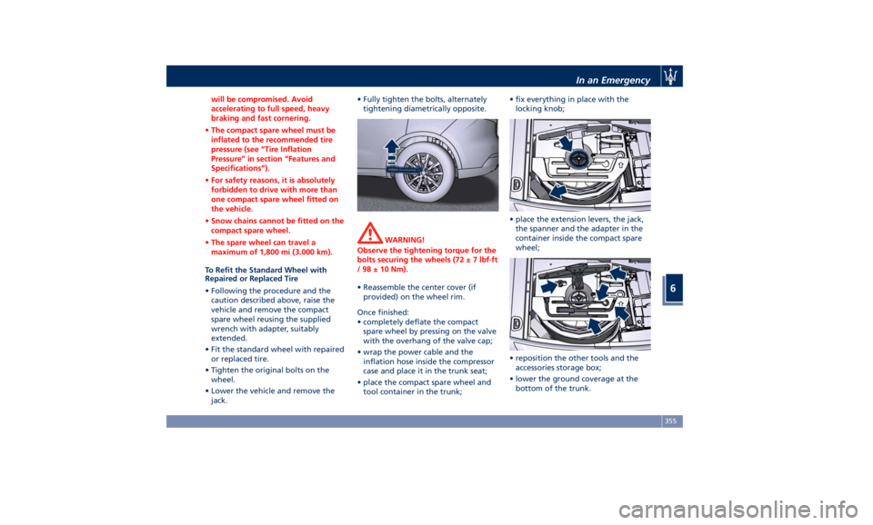
jack. • Fully tighten the bolts, alternately
tightening diametrically opposite.
WARNING!
Observe the tightening torque for the
bolts securing the wheels (72 ± 7 lbf·ft
/ 98 ± 10 Nm).
• Reassemble the center cover (if
provided)
on the wheel
rim.
Once finished:
• completely deflate the compact
spare wheel by pressing on the valve
with the overhang of the valve cap;
• wrap the power cable and the
inflation hose inside the compressor
case and place it in the trunk seat;
• place the compact spare wheel and
tool container in the trunk; • fix everything in place with the
locking knob;
• place the extension levers, the jack,
the spanner and the adapter in the
container inside the compact spare
wheel;
• reposition the other tools and the
accessories storage box;
• lower the ground coverage at the
bottom of the trunk.In an Emergency
6
355
Page 388 of 436

(Continued)
California to cause cancer and birth
defects or other reproductive harm. To
minimize exposure, avoid breathing
exhaust, do not idle the engine except
as necessary, service your vehicle in a
well-ventilated area and wear gloves
or wash your hands frequently when
servicing your vehicle. For more
information go to:
www.P65Warnings.ca.gov/passenger-
vehicle
Useful Advice to Extend
Battery Life When parking the vehicle, make sure
that the doors, hood, liftgate and flaps
are properly closed. All interior lights
should be off.
When the engine is turned off, do not
keep the connected devices switched
on for a long time (such as radio,
hazard warning flashers, fan, etc.).
CAUTION!
If the battery charge remains below
50% for a long period of time, it will
be damaged due to sulfation; its
performance and starting power will
be reduced and it will be more subject
to freezing. We recommend you to have the
battery
charge condition checked,
preferably
at the beginning of the cold
season, to prevent the electrolyte from
freezing.
This check should be carried out more
frequently if the vehicle is used mainly
for short trips or if it is equipped with
power-absorbing devices that remain
permanently on even when the
ignition switch is off. This applies
above all if these devices have been
retrofitted ("Aftermarket" services).
If the vehicle is not used for long
periods of time, please see “Vehicle
Stored for Long Periods” in this
section.
Battery Recharge WARNING!
The process of charging or recharging
the battery produces hydrogen, a
flammable gas that can explode and
cause serious injuries. When charging
or recharging the battery, follow the
recommended precautions at all times.
• Before using a charger device always
check that this tool is suitable for the
installed battery, with constant
voltage (lower than 14.0 V) and low
amperage (maximum limit 15 A). • Recharge the battery in a
well-ventilated environment.
• Never charge or recharge a frozen
battery.
• Ensure that any sparks or open
flames are kept well away from the
battery while it is charging.
• Before using a charger to charge or
maintain the battery charge status,
carefully follow the instructions
provided to ensure the charger is
connected to the battery safely and
correctly.
It is possible to recharge the battery
without
disconnecting the cables
of
the vehicle electrical system.
• To access the battery lift the ground
coverage of the trunk compartment
(see chapter “Tool Kit” section “In an
Emergency”) and remove the storage
box.
• Remove the protection cover and
connect the terminal clamp of the
charger positive cable (typically in
red) to the positive post (+) of the
battery.
• Connect the terminal clamp of the
charger negative cable (typically in
black) to the nut located by theMaintenance and Care
7
384
Page 391 of 436

• on the fuse and relay box located in
a covered area, under the dashboard
left side.
Integrated Power Module • To access the module it is necessary
to lift the hood (see “Hood
Operation” in section “Before
Starting”).
• To access the fuses remove the
module cover unhooking the lateral
locks as shown in the picture. The table points out the position as
featured in the figure, the type and
function of the fuses included in the
integrated power module.
CAUTION!
• After replacement, refit the
protective cover of the module.
• If you need to wash the engine
compartment, do not direct the
water for too long directly on the
module.
Ref. Type Function
2 Maxi – 50A Secondary air
pump relay input
(V8 engines only)
3––
4 Maxi – 30A Starter motor
relay input Ref. Type Function
5 Maxi – 40A ABS-ESP pump
feed
6 Maxi – 30A AWD module
relay input
7––
8 Maxi – 40A ABS-ESP valve
feed
9––
10 – –
11 Mini – 20A Horn relay input
12 Mini – 10A AC compressor
feed relay input
13 – –
14 Mini – 7,5A Alarm siren
15 Mini – 5A Washer heated
nozzles relay
input
16 Mini – 10A Enable cooling
fan relay input
and enable
cooling oil pump
relay input
18 – –
19 Maxi – 30A Headlamp
washer relay
inputMaintenance and Care
7
387
Page 392 of 436

Ref. Type Function
20 Maxi – 30A Wiper motor
relay output
21 Maxi – 20A LH low beam
relay input (with
Bi-Xenon
headlight) Ref. Type Function
22 Maxi – 20A RH low beam
relay input (with
Bi-Xenon
headlight)
23 – –
24 – – Ref. Type Function
28 Mini – 7,5A Drive Assist
System Module
(DASM)
29 Mini – 10A PCM module -
Starter solenoid
relay coil
30 Mini – 5A ORC- Air bag
module
31 Mini – 5A ABS-ESP module
32 Mini – 5A AWD module,
EPS and AQS
33 Mini – 10A HDLP Headlights
- AFLS
34 Mini – 15A Primary load to
engine harness
LH side
35 Mini – 15A Primary load to
engine harness
RH side
36 Mini – 30A PCM module
primary load
37 Mini – 15A Engine
secondary load
38 Mini – 15A Lambda sensorMaintenance and Care
7
388
Page 428 of 436

Abbreviations .................9
Accessories
Aftermarket Parts and Accessories
Statement .................13
Active Blind Spot Assist - ABSA . . . .310
Adaptive Cruise Control (ACC) . . . .286
Activation/Deactivation ...... .289
Display Warnings and
Maintenance ............. .294
Precautions while Driving with
ACC ................... .295
Setting the Following Distance . .291
Setting the Speed .......... .290
Airbag.....................65
Advanced Front Air Bag
Properties .................66
Air Bag Deployment Result .....71
Air Bag Deployment Sensors and
Controls ..................15
Air Bag System Components .....66
Front Air Bag Inflator Units .....70
Passenger Air bag Labels .......20
Supplemental Restraint System
(SRS) .....................65
Supplemental Seat-mounted Side
Air Bags (SAB) ..............68
Supplemental Side Air Bag Inflatable
Curtain (SABIC) ..............68
Transport of persons with
disability ..................72
Air Conditioning (A/C) System . . . .214
A/C Distribution ........... .154
Dual-zone Climate Controls . . . .214 Four-zone Climate Controls . . . .221
Alarm, Vehicle Security ..........27
ALR (Automatic Locking Retractor) . .63
Anti-Lock Braking System (ABS) and
Electronic Brake-force Distribution
(EBD) ................... .274
Assistance ...................11
Assistance, if you need ..........11
ATC (Automatic Temperature
Control) ................. .220
Audio Controls .............. .192
Audio Controls on Central
Console ................. .192
Steering Wheel Audio Controls . .192
Audio, setting .............. .207
Audio System ............... .193
Automatic Transmission
Manual Release of Transmission .360
AUX, USB and SD Memory Card
Ports .................... .135
AWD, All-Wheel Drive ......... .243
BAS (Brake Assist System) ...... .275
Battery ................... .381
Battery Recharge .......... .384
Battery Remote Posts Position. . .358
Maintaining Battery Charge . . . .403
To Disconnect the Battery .... .382
To Reconnect the Battery
..... .383
Blind
Spot Alert ............. .305
Blind
Spot Alert (BSA)
BSA System .............. .305
RCP - Rear Cross Path ........ .308 Bluetooth, Customer settings .... .208
Bodywork Maintenance and Care . .397
Pre-Short Drop Function ..... .400
Protection from Atmospheric
Agents ................. .397
Useful Advice to Keep the Bodywork
in Good Condition ......... .398
Brakes
Brake and Stability Control System
(ESC) ................... .273
Brake Overheating ......... .280
Brake System ............. .273
Manual Release of Parking
Brake .................. .356
Parking Brake ............. .268
Using the Brakes ........... .280
Capacity/Refillings ........... .406
Cargo Area ................ .139
Accessories Compartment .... .142
Cargo Area Extension ....... .143
Installing the Cargo Net ...... .144
Loading with Rear Seatbacks Folded
Down .................. .141
Luggage Fasteners and
Retainers ................ .140
Ski and Snowboard Bag
Compartment ............. .141
Trunk Compartment Cover .... .142
Vehicle Load Carrying Capacity . .139
Child Restraint Systems ..........74
Children too large for Booster
Seats .....................75Index
9 424