2019 MASERATI LEVANTE AUX
[x] Cancel search: AUXPage 233 of 436
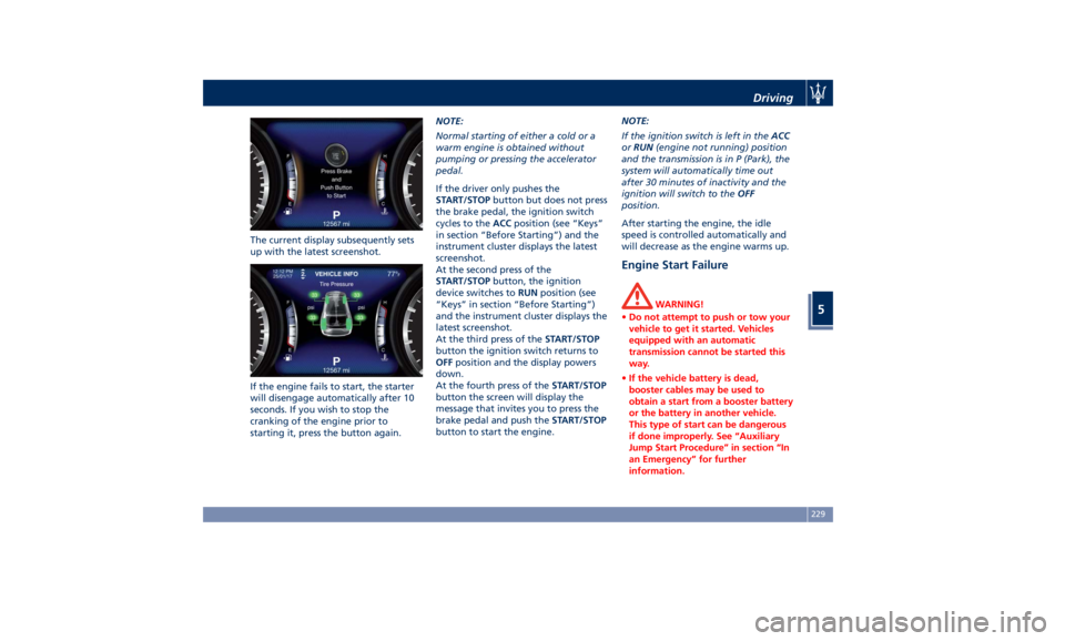
The current display subsequently sets
up with the latest screenshot.
If the engine fails to start, the starter
will disengage automatically after 10
seconds. If you wish to stop the
cranking of the engine prior to
starting it, press the button again. NOTE:
Normal starting of either a cold or a
warm engine is obtained without
pumping or pressing the accelerator
pedal.
If the driver only pushes the
START/STOP button but does not press
the brake pedal, the ignition switch
cycles to the ACC position (see “Keys”
in section “Before Starting”) and the
instrument cluster displays the latest
screenshot.
At the second press of the
START/STOP button, the ignition
device switches to RUN position (see
“Keys” in section “Before Starting”)
and the instrument cluster displays the
latest screenshot.
At the third press of the START/STOP
button the ignition switch returns to
OFF position and the display powers
down.
At the fourth press of the START/STOP
button the screen will display the
message that invites you to press the
brake pedal and push the START/STOP
button to start the engine. NOTE:
If the ignition switch is left in the ACC
or RUN (engine not running) position
and the transmission is in P (Park), the
system will automatically time out
after 30 minutes of inactivity and the
ignition will switch to the OFF
position.
After starting the engine, the idle
speed is controlled automatically and
will decrease as the engine warms up.
Engine Start Failure WARNING!
• Do not attempt to push or tow your
vehicle to get it started. Vehicles
equipped with an automatic
transmission cannot be started this
way.
• If the vehicle battery is dead,
booster cables may be used to
obtain a start from a booster battery
or the battery in another vehicle.
This type of start can be dangerous
if done improperly. See “Auxiliary
Jump Start Procedure” in section “In
an Emergency” for further
information.Driving
5
229
Page 268 of 436

Active Alternator To improve overall efficiency by
reducing the auxiliary loads on the
engine, the vehicle is equipped with a
smart alternator that is mainly active
in the latter energy balance phases
(for example, during braking, coasting
and overloading). The alternator
becomes active when the battery
charge is insufficient and when the
vehicle exits from the braking and
overload situations.
Active Alternator Feature (if feature is
available)
In the I.C.E. screen, the user can display
in the form of dynamic bars some
informative parameters on the state of
battery charge ("CHARGE"), efficiency
of drive style ("EFFICIENCY") and the
matured economy (“
” bonus range)
expressed in miles (mi) or kilometres
(km). The bonus range (about 37 mi / 60 km
for each full of fuel) is automatically
reset every time the vehicle is refueled.
Off-Road Drive This vehicle is equipped with a specific
“Off Road” driving mode which allows
to drive through various terrain
conditions (rock, mud, sand), also
uphill and downhill, eventually in
condition of lateral inclination.
To set the "OFF ROAD" drive mode,
please see the paragraphs “Setting the
Drive Mode” and “Setting Ride
Height” of chapter “Drive Mode” in
this section.
In order to enhance this specific
performance, the "OFF ROAD" drive
mode modifies the setting of:
• Ride height;
• Engine, transmission calibration;
• Suspensions.
When “OFF ROAD” is selected, ride
height is set to “Off Road 1” (vehicle is
higher by approx. 1 in / 25 mm).
It is possible to select ride height “Off
Road 2” (vehicle is raised by approx.
1.5 in / 40 mm) using the ride height
selector.
“OFF ROAD” drive mode is limited up
to a max speed of 56 mph (90 km/h). In
case the vehicle speed should exceed
this limit, the drive mode will be
de-selected automatically and the
drive mode will return to “NORMAL”.Driving
5
264
Page 351 of 436
6 – In an Emergency ToolKit .............................................. 348
Hazard Warning Flashers ................................. 350
In the Event of an Accident ............................... 350
In case of a Punctured Tire ................................ 351
Emergency Release of the Parking Brake ..................... 356
Transmission Manual Release of P (Park) Position ............... 356
Auxiliary Jump-Start Procedure ............................ 357
Towing a Disabled Vehicle ................................ 360
347
Page 361 of 436
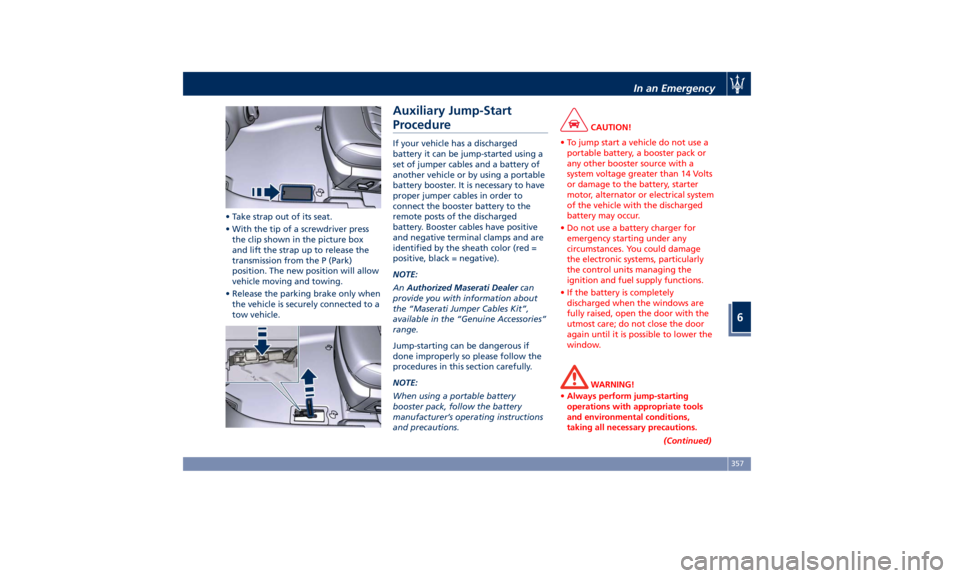
• Take strap out of its seat.
• With the tip of a screwdriver press
the clip shown in the picture box
and lift the strap up to release the
transmission from the P (Park)
position. The new position will allow
vehicle moving and towing.
• Release the parking brake only when
the vehicle is securely connected to a
tow vehicle. Auxiliary Jump-Start
Procedure If your vehicle has a discharged
battery it can be jump-started using a
set of jumper cables and a battery of
another vehicle or by using a portable
battery booster. It is necessary to have
proper jumper cables in order to
connect the booster battery to the
remote posts of the discharged
battery. Booster cables have positive
and negative terminal clamps and are
identified by the sheath color (red =
positive, black = negative).
NOTE:
An Authorized Maserati Dealer can
provide you with information about
the “Maserati Jumper Cables Kit”,
available in the “Genuine Accessories”
range.
Jump-starting can be dangerous if
done improperly so please follow the
procedures in this section carefully.
NOTE:
When using a portable battery
booster pack, follow the battery
manufacturer’s operating instructions
and precautions. CAUTION!
• To jump start a vehicle do not use a
portable battery, a booster pack or
any other booster source with a
system voltage greater than 14 Volts
or damage to the battery, starter
motor, alternator or electrical system
of the vehicle with the discharged
battery may occur.
• Do not use a battery charger for
emergency starting under any
circumstances. You could damage
the electronic systems, particularly
the control units managing the
ignition and fuel supply functions.
• If the battery is completely
discharged when the windows are
fully raised, open the door with the
utmost care; do not close the door
again until it is possible to lower the
window.
WARNING!
• Always perform jump-starting
operations with appropriate tools
and environmental conditions,
taking all necessary precautions.
(Continued)In an Emergency
6
357
Page 386 of 436
(Continued)
same type (vented).
NOTE:
Remote battery terminals for starting
are located in the engine
compartment for jump-starting to be
used with an auxiliary battery or a
battery from another vehicle (see
“Auxiliary Jump-Start Procedure”
chapter in section “In an Emergency”).
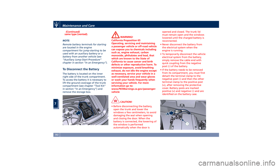
To Disconnect the Battery The battery is located on the inner
right side of the trunk compartment.
To access the battery it is necessary to
lift the ground coverage of the trunk
compartment (see chapter “Tool Kit”
in section “In an Emergency”) and
remove the storage box. WARNING!
California Proposition 65
Operating, servicing and maintaining
a passenger vehicle or off-road vehicle
can expose you to chemicals including
such as, engine exhaust, carbon
monoxide, phthalates and lead, that
which are known to the State of
California to cause cancer and birth
defects or other reproductive harm. To
minimize exposure, avoid breathing
exhaust, do not idle the engine except
as necessary, service your vehicle in a
well-ventilated area and wear gloves
or wash your hands frequently when
servicing your vehicle. For more
information go to:
www.P65Warnings.ca.gov/passenger-
vehicle
CAUTION!
• Before disconnecting the battery,
open the trunk and lower the
windows a few centimeters, to avoid
damaging the seal when opening
and closing the door. When the
battery is connected, the lowering of
the window is performed
automatically when the door is opened and closed. The trunk lid
must remain open and the windows
lowered until the charged battery is
reconnected.
• Never disconnect the battery from
the electrical system when the
engine is running.
• To temporarily disconnect the vehicle
electrical system from the battery,
simply remove the cable end with
quick coupling from the negative
post (-) of the battery.
• If the battery needs to be removed
from its compartment, you must first
detach the terminal clamp to the
negative post (-) and then the other
terminal clamp to the positive post
(+), after removing the protective
cover. Battery posts are marked
positive (+) and negative (-) and are
identified on the battery case.Maintenance and Care
7
382
Page 395 of 436

Ref. Type Function
36 Mini – 10A Transmission
lever, TPMS
module, Navtrak,
USB/AUX and
USB cherger,
ASBM Control
suspension and
Hands Free
access module
37 Mini – 25A ASCM module
38 Mini – 30A RH front seat
movement
41 Maxi – 40A ASCM motor
supply
42 – –
43 Mini – 20A Seat passenger
heater module
44 – –
45 – –
46 Mini – 5A Rear camera
47 Mini – 5A Navtrak
48 Mini – 5A Surround view
49 Mini – 10A Internal
temperature
sensor, umidity
sensor, internal
mirror and HALF Ref. Type Function
50 – –
51 Mini – 25A Rear seat and
steering wheel
heater module
52 Mini – 20A Trunk power
outlet
53 – –
54 Mini – 7,5A Blind Spot
module
55 – –
56 Mini – 10A Blower front
HVAC coil relay
57 Mini – 10A Blower rear
HVAC coil relay
58 Mini – 10A Trailer harness
(not for TROFEO
version)
59 Mini – 10A USB charger,
transmission
lever, ASBM, rear
tunnel stack
switch
60 – –
61 Mini – 15A Rear window
wiper relay
62 Mini – 7,5A Front HVAC
module Ref. Type Function
63 Mini – 20A Blower rear
HVAC
64 Mini – 7,5A Rear HVAC
module
65 Mini – 10A Intelligent
battery sensor
66 Mini – 10A Rear Seat
Entertainment
(RSE)
67 Mini – 10A Sunroof
68 Mini – 20A Power outlet on
central console
rear side
69 Mini – 25A Rear console
power outlet
and cigar lighter
70 Mini – 10A Front HVAC
module, Parking
Aid Module
(PAM), ASCM
Front HVAC
module, Parking
Aid Module
(PAM), ASCM
and ELDOR coil
(V8 engines only)Maintenance and Care
7
391
Page 428 of 436

Abbreviations .................9
Accessories
Aftermarket Parts and Accessories
Statement .................13
Active Blind Spot Assist - ABSA . . . .310
Adaptive Cruise Control (ACC) . . . .286
Activation/Deactivation ...... .289
Display Warnings and
Maintenance ............. .294
Precautions while Driving with
ACC ................... .295
Setting the Following Distance . .291
Setting the Speed .......... .290
Airbag.....................65
Advanced Front Air Bag
Properties .................66
Air Bag Deployment Result .....71
Air Bag Deployment Sensors and
Controls ..................15
Air Bag System Components .....66
Front Air Bag Inflator Units .....70
Passenger Air bag Labels .......20
Supplemental Restraint System
(SRS) .....................65
Supplemental Seat-mounted Side
Air Bags (SAB) ..............68
Supplemental Side Air Bag Inflatable
Curtain (SABIC) ..............68
Transport of persons with
disability ..................72
Air Conditioning (A/C) System . . . .214
A/C Distribution ........... .154
Dual-zone Climate Controls . . . .214 Four-zone Climate Controls . . . .221
Alarm, Vehicle Security ..........27
ALR (Automatic Locking Retractor) . .63
Anti-Lock Braking System (ABS) and
Electronic Brake-force Distribution
(EBD) ................... .274
Assistance ...................11
Assistance, if you need ..........11
ATC (Automatic Temperature
Control) ................. .220
Audio Controls .............. .192
Audio Controls on Central
Console ................. .192
Steering Wheel Audio Controls . .192
Audio, setting .............. .207
Audio System ............... .193
Automatic Transmission
Manual Release of Transmission .360
AUX, USB and SD Memory Card
Ports .................... .135
AWD, All-Wheel Drive ......... .243
BAS (Brake Assist System) ...... .275
Battery ................... .381
Battery Recharge .......... .384
Battery Remote Posts Position. . .358
Maintaining Battery Charge . . . .403
To Disconnect the Battery .... .382
To Reconnect the Battery
..... .383
Blind
Spot Alert ............. .305
Blind
Spot Alert (BSA)
BSA System .............. .305
RCP - Rear Cross Path ........ .308 Bluetooth, Customer settings .... .208
Bodywork Maintenance and Care . .397
Pre-Short Drop Function ..... .400
Protection from Atmospheric
Agents ................. .397
Useful Advice to Keep the Bodywork
in Good Condition ......... .398
Brakes
Brake and Stability Control System
(ESC) ................... .273
Brake Overheating ......... .280
Brake System ............. .273
Manual Release of Parking
Brake .................. .356
Parking Brake ............. .268
Using the Brakes ........... .280
Capacity/Refillings ........... .406
Cargo Area ................ .139
Accessories Compartment .... .142
Cargo Area Extension ....... .143
Installing the Cargo Net ...... .144
Loading with Rear Seatbacks Folded
Down .................. .141
Luggage Fasteners and
Retainers ................ .140
Ski and Snowboard Bag
Compartment ............. .141
Trunk Compartment Cover .... .142
Vehicle Load Carrying Capacity . .139
Child Restraint Systems ..........74
Children too large for Booster
Seats .....................75Index
9 424