2019 MASERATI LEVANTE lock
[x] Cancel search: lockPage 295 of 436

accelerator pedal (see “ACC
Operation Before and During Stop”
in this chapter).
• The ACC system maintains set speed
when driving up hill and down hill.
However, a slight speed change on
moderate hills is normal. In addition,
downshifting may occur while
climbing uphill or descending
downhill. This is normal operation
and necessary to maintain set speed.
When driving uphill and downhill,
the ACC system will cancel if the
braking temperature exceeds normal
range.
Temporary Deactivation A soft tap on the brake pedal, pushing
the multifunction control (CANC), or
normal brake pressure while slowing
the vehicle will temporarily deactivate
the ACC without erasing the set speed
memory. The
white light will appear
on the display with below the set
speed.
Conditions for Disabling and
Deactivation Besides the cases specified in the
previous paragraph, the following
conditions will disable the system:
• Anti-Lock Brake (ABS) kicks in. • Transmission lever is not in D (Drive).
• “CORSA” drive mode (TROFEO
version only) is set.
• Ride height is set to “Off Road 1” or
“Off Road 2”.
• The Electronic Stability Control and
the Traction Control System
(ESC/TCS) activate.
• Vehicle parking brake is operated.
• The driver safety belt is unbuckled at
low speed.
• The driver door is ajar at low speed.
• The driver disabled the ESC using the
(ESC OFF) button on central
console.
• The road is too steep both uphill and
downhill at low speed.
The system is deactivated and set
speed is deleted from system memory,
if the ACC ON/OFF button is pressed or
if ignition device is turned to OFF .
Resuming Speed If a speed setting is stored in system
memory, press the multifunction
control (RES +) up and take foot off
the accelerator pedal. The last set
speed will be displayed. WARNING!
The resume function should be used
only when road and traffic conditions
allow it. Resuming a too high or too
low speed for current traffic and road
conditions could cause a harsh vehicle
acceleration or deceleration which
could increase the risk of collisions
and death or serious injury.
Setting the ACC Gap The specified ACC gap can be set by
varying the distance setting among
the four possible options identified by
the number of horizontal bars:
• Maximum (longest) distance: 4 bars.
• Long distance: 3 bars (default
distance).
• Medium distance: 2 bars.
• Short distance: 1 bar.
Using this distance setting and the
vehicle speed, ACC calculates and sets
the gap to the vehicle ahead.
If system does not detect the presence
of any vehicles ahead, only the bars
referred to set distance will be
displayed.
When system detects the presence of a
vehicle ahead, it is displayed in front
of the bars (see example in the figure).Driving
5
291
Page 310 of 436

The BSA system monitors the detection
zones on both sides of the vehicle
when the vehicle speed reaches
approximately 6 mph (10 km/h) or
higher and will alert the driver of
vehicles in these areas.
WARNING!
• The BSA system does NOT alert the
driver about rapidly approaching
vehicles that are outside the
detection zones.
• The BSA might alert the driver too
late especially in case of rapidly
approaching vehicles.
WARNING!
Risk of accident despite Blind Spot
Assist (BSA).
BSA does not detect/react to the
following:
• Overtaking vehicles close on the
side, placing them in the blind spot
area. As a result, BSA may neither
give warnings nor intervene in such
situations. • Always pay attention to the traffic
situation and maintain a safe
distance at the side of the vehicle.
NOTE:
If
your vehicle has
experienced any
damage in the area where the sensor
is located, even if the fascia is not
damaged, the sensor may have
become misaligned. Take your vehicle
at an Authorized Maserati Dealer to
verify sensor alignment. Having a
sensor that is misaligned will result in
the BSA not operating to specification.
The area on the rear bumper fascia
where the radar sensors are located
must remain free of snow, ice, and
dirt/road contamination so that the
BSA system can function properly. Do
not cover or block the area of the rear
bumper fascia where the radar sensors
are located with foreign objects
(bumper stickers, spoilers, bicycle racks,
etc.).
The BSA system notifies the driver of
vehicles or objects in the detection
zones by illuminating the BSA warning
light located in the outside mirrors in
addition to sounding an audible
(chime) alert and reducing the radio
volume (if the radio is on). Refer to “BSA and RCP Setting” in this chapter
for further information.
The BSA system monitors the detection
zone from three different entry points
(side, rear, overtaking traffic) while
driving to see if an alert is necessary.
The BSA system will issue an alert
whenever a vehicle enters any one
detection zone as outlined below.
Speed Range of Use
Speed mph (km/h)
Minimum 6 (10)
Engaged/activated 6 (10)
Maximum – (–)
Entering from the Side
Vehicles that move into your adjacent
lanes from either side of the vehicle.Driving
5
306
Page 312 of 436

(Continued)
• The BSA system is not designed to
detect pedestrians, cyclists, or
animals.
• Even if your vehicle is equipped with
the BSA system, always check your
vehicle’s outside and rearview
mirrors for any vehicles approaching
from behind or overtaking.
• Use your turn signal before changing
lanes.
RCP - Rear Cross Path The Rear Cross Path (RCP) feature is
intended to aid the drivers when gear
in reverse of parking spaces where
their vision of oncoming vehicles may
be blocked.
The RCP system monitors the rear
detection zones on both sides of the
vehicle. Using sensors located on either
side of the rear bumper, it detects any
vehicles or objects that are moving
toward the side of the vehicle with a
minimum speed of approximately 1 to
2 mph (1 km/h to 3 km/h) to a
maximum of approximately 10 mph
(16 km/h), such as in parking lot
situations. NOTE:
In a parking lot situation, oncoming
vehicles can be obscured by vehicles
parked on either side. If the sensors
are blocked by other structures or
vehicles, the system will not be able to
alert the driver.
Proceed slowly and cautiously out of
the parking space until the rear end of
the vehicle is moderately exposed.
The RCP system will then have a clear
view of the cross traffic. If an
oncoming vehicle is detected, the RCP
system will alert the driver using both
the visual and audible alarms. If the
radio is on, it will also reduce the radio
volume.
WARNING!
RCP is not a Back Up Aid system. More specifically, it is intended to be used to
help a driver detect an oncoming
vehicle in a parking lot situation.
Drivers must be careful when backing
up, even when using RCP. Always
check carefully behind your vehicle,
look behind you, and be sure to check
for pedestrians, animals, other
vehicles, obstructions, and blind spots
before backing up. Failure to do so can
result in serious injury or death.
BSA and RCP Setting Setting modes can be selected from
the MTC+ System.
Touch “Controls” soft-key and then
“Blind Spot Assist” soft-key to enter
the setting page.
Refer to chapter “MTC+ “Controls”
Screen” in section “Dashboard
Instruments and Controls” for further
information.Driving
5
308
Page 336 of 436

emitting the same radio frequencies
as the TPMS sensors.
• Installing aftermarket window
tinting that contains materials that
may block radio wave signals.
• Accumulation of snow or ice around
the wheels or wheel housings.
• Using tire chains on the vehicle.
• Using wheels/tires not equipped with
TPMS sensors.
The instrument cluster will also display
a "Service Tire Pressure System"
message for a minimum of five
seconds when a system fault related to
an incorrect sensor location fault is
detected. In this case, the "Service Tire
Pressure System" message is then
followed by a graphic display with
pressure values still shown. This
indicates that the pressure values are
still being received from the TPMS
sensors but they may not be located in
the correct vehicle position. The system
still needs to be serviced as long as the
"Service Tire Pressure System" message
is displayed. Vehicles with Compact Spare Tire
• The compact spare tire does not have
a TPMS sensor. Therefore, the TPMS
will not monitor the pressure of the
compact spare tire.
• If you replace a tire having pressure
below the low-pressure warning
limit, with the compact spare tire, on
the next ignition switch cycle, the
TPMS light
will illuminate
followed by a beeping sound. In addition, the graphic in the
instrument cluster will still display a
flashing pressure value
corresponding to the compact tire
position.
• After driving the vehicle for up to 20
minutes above 15 mph (24 km/h), the
TPMS light
will flash for 75
seconds and then remain lit. The
instrument cluster will then display a
"Service Tire Pressure System"
message for a minimum of five
seconds and then display dashes (--)
in place of the pressure value.
• Each subsequent ignition switch cycle
will be followed by a beeping sound,
the TPMS light
will flash for 75
seconds and then remain lit. The
instrument cluster will then display a
"Service Tire Pressure System"
message for a minimum of five
seconds and subsequently displaysDriving
5
332
Page 340 of 436

(Continued)
with proper maintenance. Have the
exhaust system inspected every time
the vehicle is raised. Have any
abnormal conditions repaired
promptly. Until repaired, drive with
all side windows fully open.
WARNING!
California Proposition 65
Operating, servicing and maintaining
a passenger vehicle or off-road vehicle
can expose you to chemicals including
such as, engine exhaust, carbon
monoxide, phthalates and lead, that
which are known to the State of
California to cause cancer and birth
defects or other reproductive harm. To
minimize exposure, avoid breathing
exhaust, do not idle the engine except
as necessary, service your vehicle in a
well-ventilated area and wear gloves
or wash your hands frequently when
servicing your vehicle. For more
information go to:
www.P65Warnings.ca.gov/passenger-
vehicle Refueling Fuel Filler Neck Access To access the fuel filler neck, the filler
door must be unlocked. From outside
the vehicle, this can only be done by
pressing the unlock
or the lock
button on the key fob RKE
transmitter, in the same way as if
opening or closing the doors. If any of
the door lock controls is pressed from
inside the vehicle, the filler door will
still remain open to allow refueling.
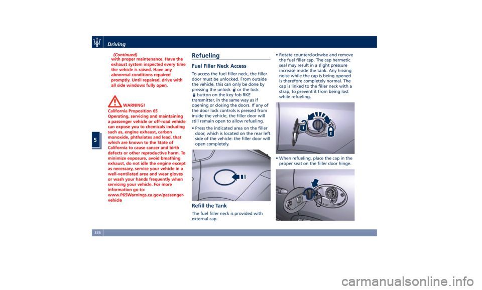
• Press the indicated area on the filler
door, which is located on the rear left
side of the vehicle: the filler door will
open completely.
Refill the Tank The fuel filler neck is provided with
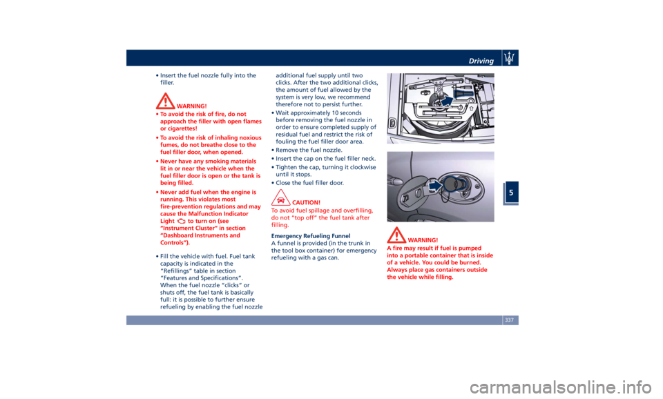
external cap. • Rotate counterclockwise and remove
the fuel filler cap. The cap hermetic
seal may result in a slight pressure
increase inside the tank. Any hissing
noise while the cap is being opened
is therefore completely normal. The
cap is linked to the filler neck with a
strap, to prevent it from being lost
while refueling.
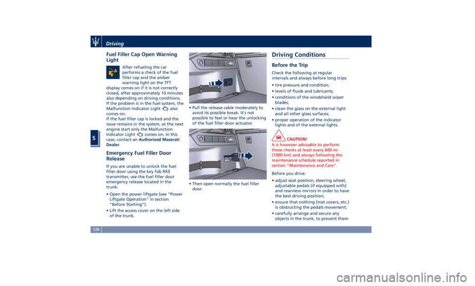
• When refueling, place the cap in the
proper seat on the filler door hinge.Driving
5
336
Page 341 of 436

• Insert the fuel nozzle fully into the
filler.
WARNING!
• To avoid the risk of fire, do not
approach the filler with open flames
or cigarettes!
• To avoid the risk of inhaling noxious
fumes, do not breathe close to the
fuel filler door, when opened.
• Never have any smoking materials
lit in or near the vehicle when the
fuel filler door is open or the tank is
being filled.
• Never add fuel when the engine is
running. This violates most
fire-prevention regulations and may
cause the Malfunction Indicator
Light
to turn on (see
“Instrument Cluster” in section
“Dashboard Instruments and
Controls”).
• Fill the vehicle with fuel. Fuel tank
capacity
is indicated in the
“Refillings” table in section
“Features and Specifications”.
When the fuel nozzle “clicks” or
shuts off, the fuel tank is basically
full: it is possible to further ensure
refueling by enabling the fuel nozzle additional fuel supply until two
clicks. After the two additional clicks,
the amount of fuel allowed by the
system is very low, we recommend
therefore not to persist further.
• Wait approximately 10 seconds
before removing the fuel nozzle in
order to ensure completed supply of
residual fuel and restrict the risk of
fouling the fuel filler door area.
• Remove the fuel nozzle.
• Insert the cap on the fuel filler neck.
• Tighten the cap, turning it clockwise
until it stops.
• Close the fuel filler door.
CAUTION!
To avoid fuel spillage and overfilling,
do not “top off” the fuel tank after
filling.
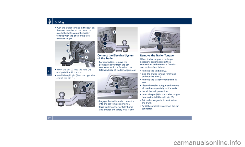
Emergency Refueling Funnel
A
funnel is provided (in the trunk in
the tool box container) for emergency
refueling with a gas can. WARNING!
A fire may result if fuel is pumped
into a portable container that is inside
of a vehicle. You could be burned.
Always place gas containers outside
the vehicle while filling.Driving
5
337
Page 342 of 436

Fuel Filler Cap Open Warning
Light After refueling the car
performs a check of the fuel
filler cap and the amber
warning light on the TFT
display comes on if it is not correctly
closed, after approximately 10 minutes
also depending on driving conditions.
If the problem is in the fuel system, the
Malfunction Indicator Light
also
comes on.
If the fuel filler cap is locked and the
issue remains in the system, at the next
engine start only the Malfunction
Indicator Light
comes on. In this
case, contact an Authorized Maserati
Dealer .
Emergency Fuel Filler Door
Release If you are unable to unlock the fuel
filler door using the key fob RKE
transmitter, use the fuel filler door
emergency release located in the
trunk.
• Open the power liftgate (see “Power
Liftgate Operation” in section
“Before Starting”).
• Lift the access cover on the left side
of the trunk. • Pull the release cable moderately to
avoid its possible break. It's not
possible to feel or hear the unlocking
of the fuel filler door actuator.
• Then open normally the fuel filler
door.Driving Conditions Before the Trip Check the following at regular
intervals and always before long trips:
• tire pressure and condition;
• levels of fluids and lubricants;
• conditions of the windshield wiper
blades;
• clean the glass on the external light
and all other glass surfaces;
• proper operation of the indicator
lights and of the external lights.
CAUTION!
It is however advisable to perform
these checks at least every 600 mi
(1000 km) and always following the
maintenance schedule reported in
section “Maintenance and Care”.
Before you drive:
•
adjust seat position, steering wheel,
adjustable pedals (if equipped with)
and rearview mirrors in order to have
the best driving position;
• ensure that nothing (mat covers, etc.)
is obstructing the pedals movement;
• carefully arrange and secure any
objects in the trunk, to prevent themDriving
5
338
Page 348 of 436

• Push the trailer tongue in the seat on
the cross member of the car up to
match the hole (A) on the trailer
tongue with the one on the cross
member support.
• Insert the pin (1) into the hole (A)
and push it until it stops.
• Install the split pin (2) at the opposite
end of the pin (1). Connect the Electrical System
of the Trailer • For connection, remove the
protective cover from the car
connector which is found on the
left-hand side of trailer tongue seat.
• Engage the trailer male connector
into the car female connector.
• Push trailer connector fully home
and engage the safety lock, if any. Remove the Trailer Tongue When trailer tongue is no longer
necessary, disconnect electrical
connections and remove it from its
seat as described below.
• Remove the split pin (2).
• Grip the trailer tongue firmly and
pull out the pin (1).
• Remove the trailer tongue from its
seat.
• Clean the trailer tongue and remove
all residues, especially on the ends.
• Install the ball protection.
• Insert the pin (1) in the trailer tongue
hole and install the split pin (2).
• Set trailer tongue in its seat inside
the trunk.
• Refit the protective cover on the car
connector.Driving
5
344