2019 MASERATI GRANTURISMO CONVERTIBLE warning light
[x] Cancel search: warning lightPage 189 of 296
exhaust, do not idle the engine except
as necessary, service your vehicle in a
well-ventilated area and wear gloves
or wash your hands frequently when
servicing your vehicle. For more
information go to:
www.P65Warnings.ca.gov/passenger-
vehicle
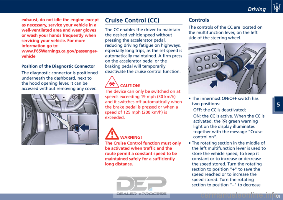
Position of the Diagnostic Connector
The
diagnostic connector is positioned
underneath the dashboard, next to
the hood opening lever. It can be
accessed without removing any cover.
Cruise Control (CC)
The CC enables the driver to maintain
the desired vehicle speed without
pressing the accelerator pedal,
reducing driving fatigue on highways,
especially long trips, as the set speed is
automatically maintained. A firm press
on the accelerator pedal or the
braking pedal will temporarily
deactivate the cruise control function.
CAUTION!
The device can only be switched on at
speeds exceeding 19 mph (30 km/h)
and it switches off automatically when
the brake pedal is pressed or when a
speed of 125 mph (200 km/h) is
exceeded.
WARNING!
The Cruise Control function must only
be activated when traffic and the
route permit a constant speed to be
maintained safely for a sufficiently
long distance.
Controls
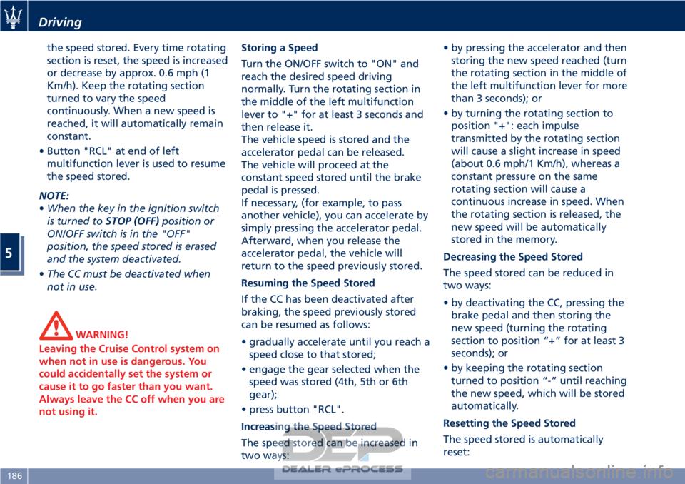
The controls of the CC are located on
the multifunction lever, on the left
side of the steering wheel.
• The innermost ON/OFF switch has two positions:
OFF: the CC is deactivated;
ON: the CC is active. When the CC is
activated, the
green warning
light on the display illuminates
together with the message “Cruise
control on”.
• The rotating section in the middle of the left multifunction lever is used to
store the vehicle speed, to keep it
constant or to increase or decrease
the speed stored. Turn the rotating
section to position "+" to save the
speed reached or to increase the
speed stored. Turn the rotating
section to position "–" to decrease
Driving
5
185
Page 190 of 296
the speed stored. Every time rotating
section is reset, the speed is increased
or decrease by approx. 0.6 mph (1
Km/h). Keep the rotating section
turned to vary the speed
continuously. When a new speed is
reached, it will automatically remain
constant.
• Button "RCL" at end of left multifunction lever is used to resume
the speed stored.
NOTE:
• When the key in the ignition switch
is turned to STOP (OFF)position or
ON/OFF switch is in the "OFF"
position, the speed stored is erased
and the system deactivated.
• The CC must be deactivated when
not in use.
WARNING!
Leaving the Cruise Control system on
when not in use is dangerous. You
could accidentally set the system or
cause it to go faster than you want.
Always leave the CC off when you are
not using it. Storing a Speed
T
urn the ON/OFF switch to "ON" and
reach the desired speed driving
normally. Turn the rotating section in
the middle of the left multifunction
lever to "+" for at least 3 seconds and
then release it.
The vehicle speed is stored and the
accelerator pedal can be released.
The vehicle will proceed at the
constant speed stored until the brake
pedal is pressed.
If necessary, (for example, to pass
another vehicle), you can accelerate by
simply pressing the accelerator pedal.
Afterward, when you release the
accelerator pedal, the vehicle will
return to the speed previously stored.
Resuming the Speed Stored
If the CC has been deactivated after
braking, the speed previously stored
can be resumed as follows:
• gradually accelerate until you reach a speed close to that stored;
• engage the gear selected when the speed was stored (4th, 5th or 6th
gear);
• press button "RCL".
Increasing the Speed Stored
The speed stored can be increased in
two ways: • by pressing the accelerator and then
storing the new speed reached (turn
the rotating section in the middle of
the left multifunction lever for more
than 3 seconds); or
• by turning the rotating section to position "+": each impulse
transmitted by the rotating section
will cause a slight increase in speed
(about 0.6 mph/1 Km/h), whereas a
constant pressure on the same
rotating section will cause a
continuous increase in speed. When
the rotating section is released, the
new speed will be automatically
stored in the memory.
Decreasing the Speed Stored
The speed stored can be reduced in
two ways:
• by deactivating the CC, pressing the brake pedal and then storing the
new speed (turning the rotating
section to position “+” for at least 3
seconds); or
• by keeping the rotating section turned to position “-” until reaching
the new speed, which will be stored
automatically.
Resetting the Speed Stored
The speed stored is automatically
reset:
Driving
5
186
Page 191 of 296
• by turning the engine off; or
• by turning ON/OFF switch to "OFF"position.
Warnings while Driving with CC
WARNING!
• When driving with CC activated, do
not shift to N (Neutral) position. It is
advisable to activate CC only when
traffic and road conditions permit
safe use of this device, that is: on
straight and dry roads, expressways
or highways, smooth flowing traffic
and smooth asphalt. Do not activate
this device when driving in town or
in heavy traffic.
• CC can only be activated at speeds
exceeding 19 mph (30 km/h).
• CC can only be activated in 4th, 5th
or 6th gear, depending upon the
vehicle speed.
• When driving downhill with the CC
activated, the vehicle may pick up
speed slightly exceeding the speed
stored, due to the change in the
engine load.
• In the event of malfunctioning or
failure of CC, turn ON/OFF switch to
"OFF" position and contact the
Authorized Maserati Dealer after having checked that the relative
fuse is in proper working order.
• ON/OFF switch can be always left at
"ON" position without damaging
the CC. In any case, it is advisable to
deactivate the CC when it is not in
use. Turn ON/OFF switch to "OFF"
position to prevent any speeds from
being unintentionally stored.
Tires - General
Information
Tire Safety Information
Tire Markings
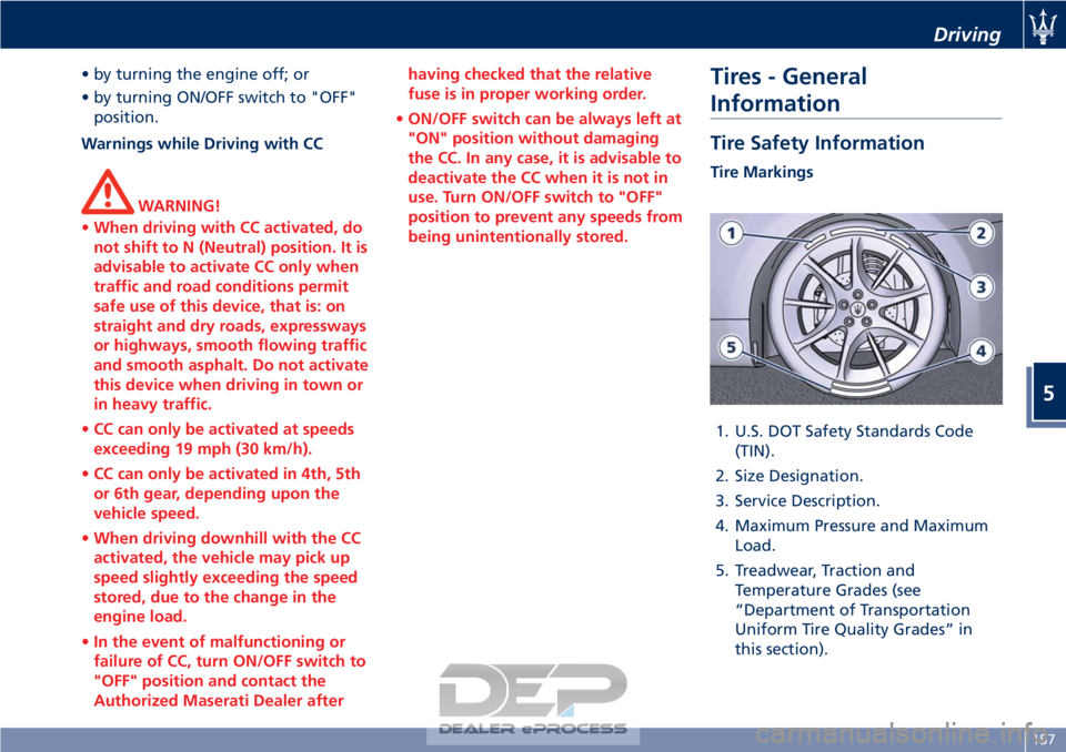
1. U.S. DOT Safety Standards Code (TIN).
2. Size Designation.
3. Service Description.
4. Maximum Pressure and Maximum Load.
5. Treadwear, Traction and Temperature Grades (see
“Department of Transportation
Uniform Tire Quality Grades” in
this section).
Driving
5
187
Page 200 of 296

(Continued)
style. Aftermarket wheels can cause
sensor damage. Do not use
aftermarket tire sealants or balance
beads, as damage to the sensors may
result.
• The system can temporarily experience radio-electric interference
emitted by devices using similar
frequencies.
• After inspecting or adjusting the tire pressure, always reinstall the valve
stem cap. This will prevent moisture
and dirt from entering the valve
stem and damage the TPMS internal
sensor.
NOTE:
• Driving
on a significantly
underinflated tire causes the tire to
overheat and may lead to tire failure.
Under-inflation also reduces fuel
efficiency and tire tread life, and may
affect the vehicle’s handling and
stopping ability.
• The TPMS is not a substitute for
proper tire maintenance, and it is the
driver’s responsibility to maintain
correct tire pressure using an
accurate tire pressure gage, even if
under-inflation has not reached the level to trigger illumination of the
TPMS light
.
• Seasonal temperature changes will
affect tire pressure, and the TPMS
will monitor the actual tire pressure
in the tire.
Viewing Messages on the
Display
By pressing repeatedly the “MODE”
button of the control panel on left
side of the steering column, the user
can access the information page that
shows the pressure values of each tire
(“Tire Pressure” screen page: see
paragraph "TFT Display: Screen Pages"
in chapter "Instrument Cluster" of
section "Dashboard Instruments and
Controls").
If system faults or low pressure is
detected on a not indentified tire, "Check Tire Pressure" or "TPMS
Malfunction" pop-up message will be
displayed for 10 seconds. The
amber warning light will
permanently illuminate on the right
side of the instrument cluster display.
With a malfunction detected, the "Tire
Pressure" screen page will not be
available while will be available the
calibration screen page.
The “Tire Pressure” screen page
becomes available again, until the
malfunction is corrected.
Low Tire Pressure Conditions
The signal transmitted by the ECU
activates messages and symbols on the
TFT display with two priority levels
corresponding to the following
thresholds:
• Soft Warning: if the pressure is 10% lower than the rated pressure;
• Hard Warning: if the pressure is 17% lower than the rated pressure.
The system refers to the rated pressure
acquired after calibration.
The two alarm thresholds for
monitoring the tire pressure
respectively activate the following
alerts:
• “Check tire pressure” illuminates on the display when the pressure of one
Driving
5
196
Page 201 of 296
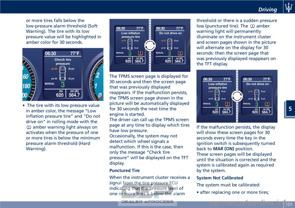
or more tires falls below the
low-pressure alarm threshold (Soft
Warning). The tire with its low
pressure value will be highlighted in
amber color for 30 seconds.
• The tire with its low pressure value in amber color, the message “Low
inflation pressure tire” and "Do not
drive on" in rolling mode with the
amber warning light always on
activates when the pressure of one
or more tires is below the minimum
pressure alarm threshold (Hard
Warning). The TPMS screen page is displayed for
30 seconds and then the screen page
that was previously displayed
reappears. If the malfunction persists,
the TPMS screen page shown in the
picture will be automatically displayed
for 30 seconds the next time the
engine is started.
The driver can call up the TPMS screen
page at any time to display which tires
have low pressure.
Occasionally, the system may not
detect which wheel signals a
malfunction. If this is the case, then
only the message “Check tire
pressure” will be displayed on the TFT
display.
Punctured Tire
When the instrument cluster receives a
signal from the tire pressure ECU
indicating that the pressure level of
one or more tires is below the alarm threshold or there is a sudden pressure
loss (punctured tire). The
amber
warning light will permanently
illuminate on the instrument cluster
and screen pages shown in the picture
will alternate on the display for 30
seconds: then the screen page that
was previously displayed reappears on
the TFT display.
If the malfunction persists, the display
will show these screen pages for 30
seconds every time the key in the
ignition switch is subsequently turned
back to MAR (ON) position.
These screen pages will be displayed
until the situation is corrected and the
system is calibrated again as required
by the system.
System Not Calibrated
The system must be calibrated:
• after replacing one or more tires;
Driving
5
197
Page 202 of 296
• after inverting the wheels;
• if you are not sure whether at leastone of the operations above was
performed.
If you simply corrected the tire
inflation pressure, you do not need to
recalibrate the system.
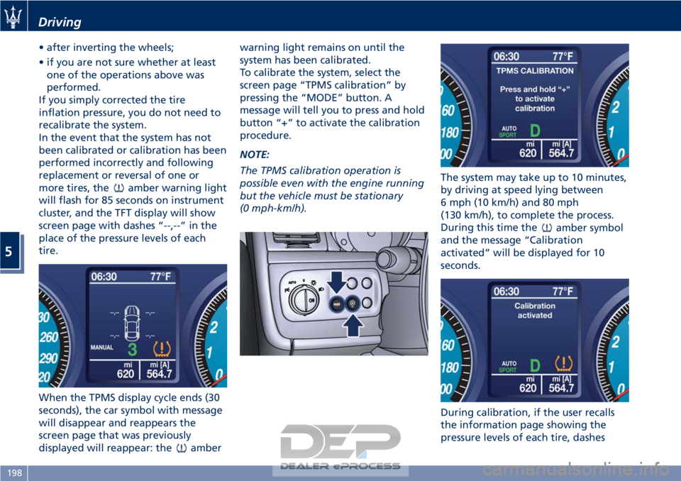
In the event that the system has not
been calibrated or calibration has been
performed incorrectly and following
replacement or reversal of one or
more tires, the
amber warning light
will flash for 85 seconds on instrument
cluster, and the TFT display will show
screen page with dashes “--,--” in the
place of the pressure levels of each
tire.
When the TPMS display cycle ends (30
seconds), the car symbol with message
will disappear and reappears the
screen page that was previously
displayed will reappear: the
amber warning light remains on until the
system has been calibrated.
To calibrate the system, select the
screen page “TPMS calibration” by
pressing the “MODE” button. A
message will tell you to press and hold
button “+” to activate the calibration
procedure.
NOTE:
The TPMS calibration operation is
possible even with the engine running
but the vehicle must be stationary
(0 mph-km/h).
The system may take up to 10 minutes,
by driving at speed lying between
6 mph (10 km/h) and 80 mph
(130 km/h), to complete the process.
During this time the
amber symbol
and the message “Calibration
activated” will be displayed for 10
seconds.
During calibration, if the user recalls
the information page showing the
pressure levels of each tire, dashes
Driving
5
198
Page 203 of 296

“--,--” will be displayed in the place of
the values.
NOTE:
•The system will not perform
calibration if the pressure is below 2
bar (29 psi).
• To allow the system to acquire the
sensors’s data, after the startup of
the car, if possible avoid to stop.
During this interval the TFT display
can show screen page with dashes
“--,--” in the place of the pressure
levels of each tire.
• If calibration is not completed within
10 minutes of driving the car, the
instrument cluster shows “TPMS
Malfunction” pop-up message and
“Tire Pressure” screen disappear. The
warning light remains light on.
TPMS Malfunction
Screen page shown in picture may
appear in the following cases:
• malfunction in the ECU
system/wiring;
• no signal reception by one or more sensors due to malfunctioning,
broken or dead battery;
• ECU malfunction. The display procedure follows the
usual logic of malfunctions. Therefore,
after 30 seconds, the display will show
the screen page that was active before
the malfunction occurred.
In addition to screen page being
displayed, the
amber warning
light, which is permanently
illuminated on the instrument cluster,
will flash for 85 seconds, after which it
will remain permanently on until the
situation is corrected. The information
page that shows the pressure value for
each tire cannot be recalled.
Fuel Requirements
The engines are designed to meet all
environmental regulations and
provide excellent fuel economy and
performance when using unleaded
premium gasoline with an AKI octane
rating of 91 or above. AKI (Anti Knock
Index) is an average on the Research
Octane Number, RON, and the Motor
Octane Number, MON (RON + MON/2
gives you the AKI).
For vehicle top performance, use
unleaded premium gasoline with no
less than 93 minimum AKI octane
rating.
Poor quality gasoline can cause
problems such as hard starting,
stalling, and hesitations. If you
experience these symptoms, try
another brand of gasoline before
considering service for the vehicle at
an Authorized Maserati Dealer .
Besides using unleaded gasoline with
the proper octane rating, gasoline
that contain detergents, anti-corrosion
and stability additives are
recommended. Using gasoline that
have these additives may help improve
fuel economy, reduce emissions, and
maintain vehicle performance.
Driving
5
199
Page 206 of 296
Refueling
Fuel Filler Neck Access
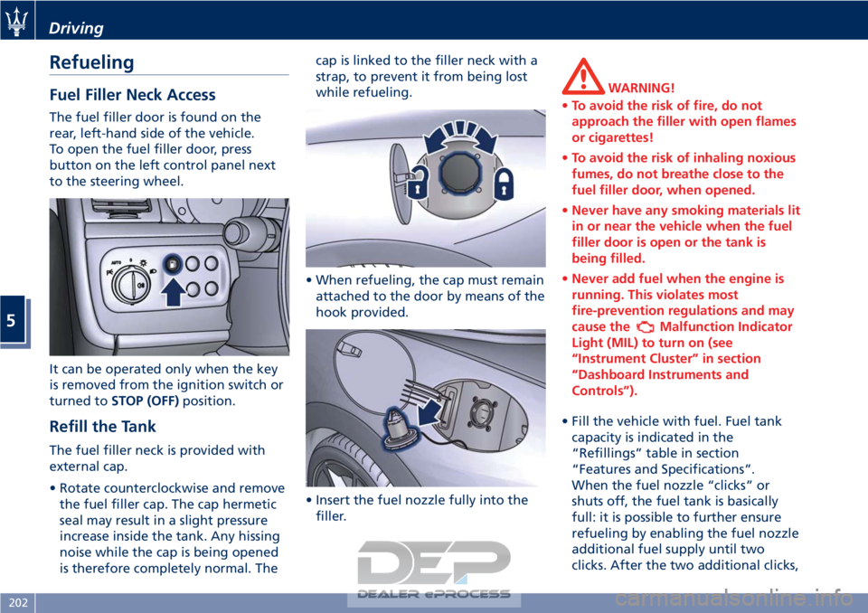
The fuel filler door is found on the
rear, left-hand side of the vehicle.
To open the fuel filler door, press
button on the left control panel next
to the steering wheel.
It can be operated only when the key
is removed from the ignition switch or
turned toSTOP (OFF) position.
Refill the Tank
The fuel filler neck is provided with
external cap.
• Rotate counterclockwise and remove
the fuel filler cap. The cap hermetic
seal may result in a slight pressure
increase inside the tank. Any hissing
noise while the cap is being opened
is therefore completely normal. The cap is linked to the filler neck with a
strap, to prevent it from being lost
while refueling.
• When refueling, the cap must remain attached to the door by means of the
hook provided.
• Insert the fuel nozzle fully into the filler.
WARNING!
• To avoid the risk of fire, do not
approach the filler with open flames
or cigarettes!
• To avoid the risk of inhaling noxious
fumes, do not breathe close to the
fuel filler door, when opened.
• Never have any smoking materials lit
in or near the vehicle when the fuel
filler door is open or the tank is
being filled.
• Never add fuel when the engine is
running. This violates most
fire-prevention regulations and may
cause the
Malfunction Indicator
Light (MIL) to turn on (see
“Instrument Cluster” in section
“Dashboard Instruments and
Controls”).
• Fill the vehicle with fuel. Fuel tank capacity
is indicated in the
“Refillings” table in section
“Features and Specifications”.
When the fuel nozzle “clicks” or
shuts off, the fuel tank is basically
full: it is possible to further ensure
refueling by enabling the fuel nozzle
additional fuel supply until two
clicks. After the two additional clicks,
Driving
5
202