2019 MASERATI GRANTURISMO CONVERTIBLE ABS
[x] Cancel search: ABSPage 192 of 296
Tire Sizing Chart
EXAMPLE: P285/40 ZR19 (100Y) XL or
285/40 ZR19 (Y100) XL
Size Designation:
P= Passenger car tire size based on
U.S. design standards
“...blank...” = Passenger car tire
based on European design standards
285 = Section width in millimeters
(mm)
40 = Aspect ratio in percent (%) —
Ratio of section height to section
width of tire
ZR = Construction Code
• Z: means a tire usable at speeds greater than 150 mph (240 km/h)
• R: means radial construction
19 = Rim diameter in inches (in)
Service Description:
100 = Load Index — A numerical
code associated with the maximum
load a tire can carry
Y = Speed Symbol — A symbol
indicating the range of speeds at
which a tire can carry a load
corresponding to its load index
under certain operating conditions.
The maximum speed corresponding
to the speed symbol should only be
achieved under specified operating
conditions (i.e., tire pressure, vehicle
loading, road conditions, and posted
speed limits)
Load Identification:
“...blank...” = Absence of any text on
the sidewall of the tire indicates a
Standard Load (SL) tire
XL = Extra Load (or reinforced) tire
LL = Light Load tire
Tire Identification Number (TIN)
The TIN may be found on one or both
sides of the tire, however the date
code may only be on one side. Tires
with white sidewalls will have the full
TIN, including the date code, located
on the white sidewall side of the tire. Look for the TIN on the outboard side
of black sidewall tires as mounted on
the vehicle. If the TIN is not found on
the outboard side, then you will find it
on the inboard side of the tire.
EXAMPLE: DOT MA L9 ABCD 0313
DOT
= Department of Transportation
— This symbol certifies that the tire is
in compliance with the U.S.
Department of Transportation tire
safety standards and is approved for
highway use.
MA = Code representing the tire
manufacturing location (two digits).
L9 = Code representing the tire size
(two digits).
ABCD = Code used by the tire
manufacturer (one to four digits).
03 = Number representing the week
in which the tire was manufactured
(two digits). In this case, 03 means
the 3
rdweek.
13 = Number representing the year
in which the tire was manufactured
(two digits). In this case, 13 means
the year 2013.
Driving
5
188
Page 213 of 296
The weight of the vehicle affects fuel
consumption considerably.
• Use the vehicle devices or accessories which absorb electrical power only
as long as necessary. The power
required increases fuel consumption.
Driving
5
209
Page 221 of 296

• Remove from the compressor casethe inflation hose and the cable with
a plug for the power outlet.
• Unscrew the valve cap of the compact spare wheel and screw the
fitting of the inflation hose onto the
valve.
• Insert the plug in one of the available power outlets fitted in the
trunk or passenger compartment.
• Turn the key in the ignition switch in MAR (ON) position.
• Turn the compressor on by pressing the switch.
• Stop the compressor pressing switch again, when the pressure indicated
by the gage reaches the
recommended level (see “Tire
Inflation Pressure” in section
“Features and Specifications”) and
screw the cap on the compact spare
wheel valve.
CAUTION!
• In order to obtain a more accurate reading, the compressor should be
switched off when checking the tire
pressure of the compact spare wheel
on the pressure gage.
• Do not run the compressor for more than 20 minutes: there is a risk it
could overheat. Also, prolonged
power absorption may discharge the
battery, subsequently preventing the
engine from starting.
• The compressor has been designed exclusively to inflate compact spare
wheels; do not use it to inflate air
mattresses, dinghies etc.
• Fit the adapter on the wrench. Extend
the wrench as shown, then
loosen by approximately one turn, the five bolts on the wheel to be
changed.
• Open the jack partially, releasing and turning the control lever clockwise.
• Place the jack near the wheel to be changed in one of the indicated
positions.
• Make sure that the head of the jack is correctly inserted in one of the
slots beneath the sole bar.
In an Emergency
6
217
Page 223 of 296
approximately 44 lb (20 kg) being
placed on the handle of the wrench
supplied when extended for use.
• After refitting the standard wheel,
check the tire pressure.
WARNING!
• The spare wheel is narrower than
standard wheels and must only be
used to travel the distance required
to reach a service station, where the
punctured tire can be repaired or
replaced.
• Do not exceed a maximum speed of
50 mph (80 km/h) when using the
compact spare wheel; when this
limit is exceeded, the stability, road
holding and braking of the vehicle
will be compromised. Avoid
accelerating to full speed, heavy
braking and fast cornering.
• The compact spare wheel must be
inflated to the recommended tire
pressure (see “Tire Inflation
Pressure” in section “Features and
Specifications”).
• For safety reasons, it is absolutely
forbidden to drive with more than
one compact spare wheel fitted on
the vehicle. •
Snow chains cannot be fitted on the
compact spare wheel.
• The spare wheel can travel a
maximum of 1,800 mi (3.000 km).
NOTE:
The
used wheel may soil the mats if it
is housed in the car: insert the used
wheel in the protective bag housed in
the side pocket of the covering bag.
To Refit the Standard Wheel with
Repaired or Replaced Tire
• Following the procedure and the caution described above, raise the
vehicle and remove the compact
spare wheel reusing the supplied
wrench with adapter, suitably
extended.
• Fit the standard wheel with repaired or replaced tire.
• Tighten the original bolts on the wheel.
• Lower the vehicle and remove the jack.
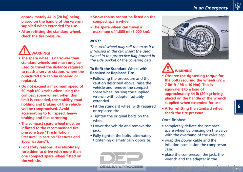
• Fully tighten the bolts, alternately tightening diametrically opposite.
WARNING!
• Observe the tightening torque for
the bolts securing the wheels (72 ±
7 lbf·ft / 98 ± 10 Nm). This is
equivalent to a load of
approximately 44 lb (20 kg) being
placed on the handle of the wrench
supplied when extended for use.
• After refitting the standard wheel,
check the tire pressure.
Once finished:
•
completely deflate the compact
spare wheel by pressing on the valve
with the overhang of the valve cap;
• wrap the power cable and the inflation hose inside the compressor
case;
• place the compressor, the jack, the wrench and the adapter in the
In an Emergency
6
219
Page 240 of 296
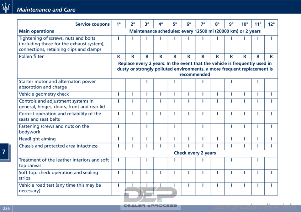
Service coupons 1° 2° 3° 4° 5° 6° 7° 8° 9° 10° 11° 12°
Main operations Maintenance schedules: every 12500 mi (20000 km) or 2 years
Tightening of screws, nuts and bolts
(including those for the exhaust system),
connections, retaining clips and clamps IIIIIIIIIIII
Pollen filter RRRRRRRRRRRR
Replace every 2 years. In the event that the vehicle is frequently used in
dusty or strongly polluted environments, a more frequent replacement is recommended
Starter motor and alternator: power
absorption and charge III II
Vehicle geometry check IIIIIIIIIIII
Controls and adjustment systems in
general, hinges, doors, front and rear lid IIIIIIIIIIII
Correct operation and reliability of the
seats and seat belts IIIIIIIIIIII
Fastening screws and nuts on the
bodywork IIIIIIII
Headlight aiming IIIIIIIIIIII
Chassis and protected area intactness IIIIIIIIIIII
Check every 2 years
Treatment of the leather interiors and soft
top canvas IIIIII
Soft top: check operation and sealing
strips IIIIIIIIIIII
Vehicle road test (any time this may be
necessary) IIIIIIIIIIII
Maintenance and Care
7
236
Page 246 of 296
(Continued)
www.P65Warnings.ca.gov/passenger-
vehicle
Brake Fluid Level Check
Check
the fluid level immediately if
the brake system
red warning
light and the related message turn on
indicating a low level of brake fluid.
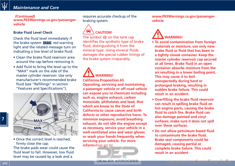
• Clean the brake fluid reservoir area around the cap before removing it.
• Add fluid to bring the level up to the “MAX” mark on the side of the
master cylinder reservoir. Use only
manufacturer's recommended brake
fluid (see “Refillings” in section
"Features and Specifications").
• Once the correct level is reached, firmly close the cap.
The brake pads wear could cause the
fluid level to fall. However, low fluid
level may be caused by a leak and a requires accurate checkup of the
braking system.
CAUTION!
The symbol
on the tank cap
identifies the synthetic type of brake
fluid, distinguishing it from the
mineral type. Using mineral fluids
damages the special rubber linings of
the brake system irreparably.
WARNING!
California Proposition 65
Operating, servicing and maintaining
a passenger vehicle or off-road vehicle
can expose you to chemicals including
such as, engine exhaust, carbon
monoxide, phthalates and lead, that
which are know to the State of
California to cause cancer and birth
defects or other reproductive harm. To
minimize exposure, avoid breathing
exhaust, do not idle the engine except
as necessary, service your vehicle in a
well-ventilated area and wear gloves
or wash your hands frequently when
servicing your vehicle. For more
information go to: www.P65Warnings.ca.gov/passenger-
vehicle
WARNING!
• To avoid contamination from foreign
materials or moisture, use only new
brake fluid or fluid that has been in
a tightly closed container. Keep the
master cylinder reservoir cap secured
at all times. Brake fluid in an open
container absorbs moisture from the
air resulting in a lower boiling point.
This may cause it to boil
unexpectedly during hard or
prolonged braking, resulting in
sudden brake failure. This could
result in an accident.
• Overfilling the brake fluid reservoir
can result in spilling brake fluid on
hot engine parts, causing the brake
fluid to catch fire. Brake fluid can
also damage painted and vinyl
surfaces, make sure it does not spill
over these surfaces.
• Do not allow petroleum based fluid
to contaminate the brake fluid.
Brake seal components could be
damaged, causing partial or
complete brake failure. This could
result in an accident.
Maintenance and Care
7
242
Page 253 of 296
self-learning cycle. At the same time,
you can run the date and time set up
procedure for the MTC.
• Every time the battery is reconnected the
and
warning lights will flash for
about 10 seconds and then go off.
WARNING!
California Proposition 65
Operating, servicing and maintaining
a passenger vehicle or off-road vehicle
can expose you to chemicals including
such as, engine exhaust, carbon
monoxide, phthalates and lead, that
which are know to the State of
California to cause cancer and birth
defects or other reproductive harm. To
minimize exposure, avoid breathing
exhaust, do not idle the engine except
as necessary, service your vehicle in a
well-ventilated area and wear gloves
or wash your hands frequently when
servicing your vehicle. For more
information go to:
www.P65Warnings.ca.gov/passenger-
vehicle
Useful Advice to Extend
Battery Life
When parking the vehicle, make sure
that the doors, front, rear lids and
flaps are properly closed. All interior
lights should be off.
When the engine is turned off, do not
keep the connected devices switched
on for a long time (such as radio,
hazard warning flashers, fan, etc.).
CAUTION!
If the battery charge remains below
50% for a long period of time, it will
be damaged due to sulfation; its
performance and starting power will
be reduced and it will be more subject
to freezing (this can happen even at
14°F/-10°C).
We recommend you to have the
battery
charge condition checked,
preferably at the beginning of the
cold season, to prevent the electrolyte
from freezing.
This check should be carried out more
frequently if the vehicle is used mainly
for short trips or if it is equipped with
power absorbing devices that remain
permanently on even when the
ignition switch is off. This applies above all if these devices have been
retrofitted ("Aftermarket" services).
If the vehicle is not used for long
periods of time, please see “Vehicle
Stored for Long Periods” in this
section.
Battery Recharge
WARNING!
The process of charging or recharging
the battery produces hydrogen, a
flammable gas that can explode and
cause serious injuries. When charging
or recharging the battery, follow the
recommended precautions at all
times.
• Before using a charger device
always check that this tool is
suitable for the installed battery,
with constant voltage (lower than
14.8 V) and low amperage
(maximum limit 15 A).
• Recharge the battery in a
well-ventilated environment.
• Never charge or recharge a frozen
battery: it can explode due to
hydrogen trapped inside the ice
crystals.
• Ensure that any sparks or open
(Continued)
Maintenance and Care
7
249
Page 256 of 296
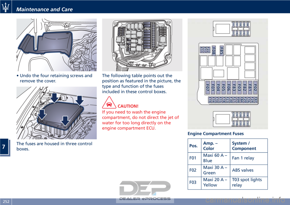
• Undo the four retaining screws andremove the cover.
The fuses are housed in three control
boxes. The following table points out the
position as featured in the picture, the
type and function of the fuses
included in these control boxes.
CAUTION!
If you need to wash the engine
compartment, do not direct the jet of
water for too long directly on the
engine compartment ECU. Engine Compartment Fuses
Pos.Amp. –
Color System /
Component
F01 Maxi 60 A –
Blue Fan 1 relay
F02 Maxi 30 A –
Green ABS valves
F03 Maxi 20 A –
Yellow T03 spot lights
relay
Maintenance and Care
7
252