2019 MASERATI GHIBLI spare wheel
[x] Cancel search: spare wheelPage 313 of 384

the “Wheel Security Stud Bolt Kit”,
available in the “Genuine
Accessories” range.
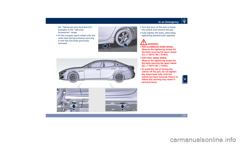
• Fit the compact spare wheel with the
valve stem facing outward, securing
it with the five bolts previously
removed. • Turn the lever of the jack to lower
the vehicle and remove the jack.
• Fully tighten the bolts, alternately
tightening diametrically opposite.
WARNING!
• FOR ALUMINIUM SPARE WHEEL
Observe the tightening torque for
the bolts securing the spare wheel
(72 ± 7 lbf·ft/ 98 ± 10 Nm).
• FOR STEEL SPARE WHEEL
Observe the tightening torque for
the bolts securing the spare wheel
(63 ± 7 lbf·ft/ 86 ± 10 Nm).
• To avoid the risk of forcing the
vehicle off the jack, do not tighten
the wheel bolts fully until the
vehicle has been lowered. Failure to
follow this warning may result in
personal injury.In an Emergency
6
309
Page 314 of 384

WARNING!
• The spare wheel is narrower than
standard wheels and must only be
used to travel the distance required
to reach a service station, where the
punctured tire can be repaired or
replaced.
• Do not exceed a maximum speed of
50 mph (80 km/h) when using the
compact spare wheel; when this
limit is exceeded, the stability, road
holding and braking of the vehicle
will be compromised. Avoid
accelerating to full speed, heavy
braking and fast cornering.
• The compact spare wheel must be
inflated to the recommended tire
pressure (see “Tire Inflation
Pressure” in section “Features and
Specifications”). • For safety reasons, it is absolutely
forbidden to drive with more than
one compact spare wheel fitted on
the vehicle.
• Snow chains cannot be fitted on the
compact spare wheel.
• The spare wheel can travel a
maximum of 1,800 mi (3.000 km).
To Refit the Standard Wheel with
Repair
ed or Replaced Tire
• Following the procedure and the
caution described above, raise the
vehicle and remove the compact
spare wheel reusing the supplied
wrench with adapter, suitably
extended.
• Fit the standard wheel with repaired
or replaced tire.
• Tighten the original bolts on the
wheel.
• Lower the vehicle and remove the
jack.
• Fully tighten the bolts, alternately
tightening diametrically opposite. WARNING!
Observe the tightening torque for the
bolts securing the wheels (72 ± 7 lbf·ft
/ 98 ± 10 Nm). Check the correct
tightening torque as soon possible
contacting an Authorized Maserati
Dealer.
• Reassemble the center cover (if
equipped)
on the wheel rim.
Once finished:
• completely deflate the compact
spare wheel by pressing on the valve
with the overhang of the valve cap;
• place the compact spare wheel and
tool container in the trunk;
• fix everything in place with the
locking knob;In an Emergency
6
310
Page 315 of 384

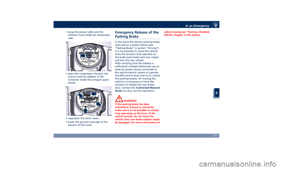
• wrap the power cable and the
inflation hose inside the compressor
case;
• place the compressor, the jack, the
wrench and the adapter in the
container inside the compact spare
wheel;
• reposition the other tools;
• lower the ground coverage at the
bottom of the trunk. Emergency Release of the
Parking Brake In the event the electric parking brake
locks due to a system failure (see
“Parking Brake” in section “Driving”),
it is not possible to move the vehicle,
since the actuator that operates on
the brake pad inside each rear caliper
will lock the rear wheels.
After verifying that the battery is
sufficiently charged (otherwise use an
external power source connected to
the vehicle electric system to operate
the EPB control lever and try to unlock
the parking brake), for moving the
vehicle it is necessary to force the
actuator to release the rear brake
discs. Contact the Authorized Maserati
Dealer to carry out this operation.
WARNING!
If the parking brake has been
activated in manual or automatic
mode and it is not possible to release
it by operating on the lever of the
central console, do not move the
vehicle since rear brake calipers might
be damaged. For more information on vehicle towing see "Towing a Disabled
Vehicle" chapter in this section.
In an Emergency
6
311
Page 370 of 384

Wheels NOTE:
• Maserati recommends Maserati Genuine Tires marked with “MGT” logo specifically designed for its models.
• In order to maintain high performance and safety level, Maserati recommends to use tires equivalent to the original
size.
WARNING!
• The maximum speed reachable with the tires is indicated by the tire manufacturer. Always comply with the regulations
in force in the Country you are driving in.
• Never exceed the maximum speed indicated for the tires: failure to respect the max. speed may damage these tires.
Danger: risk of accident!
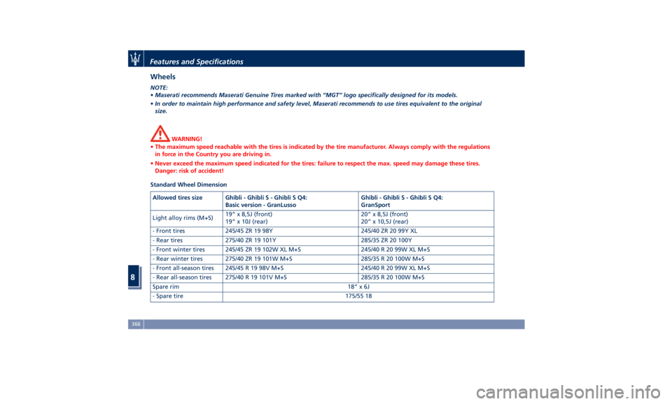
Standard Wheel Dimension
Allowed tires size Ghibli - Ghibli S - Ghibli S Q4:
Basic version - GranLusso Ghibli - Ghibli S - Ghibli S Q4:
GranSport
Light alloy rims (M+S) 19” x 8,5J (front)
19” x 10J (rear) 20” x 8,5J (front)
20” x 10,5J (rear)
- Front tires 245/45 ZR 19 98Y 245/40 ZR 20 99Y XL
- Rear tires 275/40 ZR 19 101Y 285/35 ZR 20 100Y
- Front winter tires 245/45 ZR 19 102W XL M+S 245/40 R 20 99W XL M+S
- Rear winter tires 275/40 ZR 19 101W M+S 285/35 R 20 100W M+S
- Front all-season tires 245/45 R 19 98V M+S 245/40 R 20 99W XL M+S
- Rear all-season tires 275/40 R 19 101V M+S 285/35 R 20 100W M+S
Spare rim 18” x 6J
- Spare tire 175/55 18Features and Specifications
8
366
Page 374 of 384

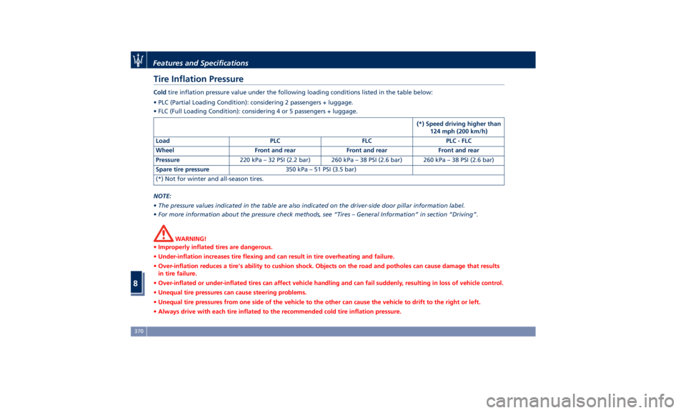
Tire Inflation Pressure Cold tire inflation pressure value under the following loading conditions listed in the table below:
• PLC (Partial Loading Condition): considering 2 passengers + luggage.
• FLC (Full Loading Condition): considering 4 or 5 passengers + luggage.
(*) Speed driving higher than
124 mph (200 km/h)
Load PLC FLC PLC - FLC
Wheel Front and rear Front and rear Front and rear
Pressure 220 kPa – 32 PSI (2.2 bar) 260 kPa – 38 PSI (2.6 bar) 260 kPa – 38 PSI (2.6 bar)
Spare tire pressure 350 kPa – 51 PSI (3.5 bar)
(*) Not for winter and all-season tires.
NOTE:
• The pressure values indicated in the table are also indicated on the driver-side door pillar information label.
• For more information about the pressure check methods, see “Tires – General Information” in section “Driving”.
WARNING!
• Improperly inflated tires are dangerous.
• Under-inflation increases tire flexing and can result in tire overheating and failure.
• Over-inflation reduces a tire's ability to cushion shock. Objects on the road and potholes can cause damage that results
in tire failure.
• Over-inflated or under-inflated tires can affect vehicle handling and can fail suddenly, resulting in loss of vehicle control.
• Unequal tire pressures can cause steering problems.
• Unequal tire pressures from one side of the vehicle to the other can cause the vehicle to drift to the right or left.
• Always drive with each tire inflated to the recommended cold tire inflation pressure.Features and Specifications
8
370
Page 380 of 384

Spare parts service
Genuine Parts ..............13
Scheduled Maintenance .......13
Spare Parts Service .............13
SRS (Supplemental Restraint
System) ....................64
Start&Stop System ........... .210
Occupant Safety Function .... .212
Start&Stop Active Indicator . . . .148
Start&Stop Disable Indicator . . . .167
Start&Stop Failure Indicator
Light ................... .167
Start&Stop Function Disabling
Indicator ................ .212
Start&Stop Menu .......... .158
Start&Stop System Failure .... .214
Start the Engine
Engine Start Failure ......... .209
Engine Turn Off ........... .210
Steering Wheel
Heated Steering Wheel ...... .106
Phone and Voice Controls on
Steering Wheel ............ .204
Sunroof
Pinch Protect Feature ....... .137
Slide Opening Sunroof ....... .137
Sunroof Maintenance ....... .138
Venting Sunroof ........... .137
Sunshades ................. .136
Power Sunshades ............47
Sun Visors ................. .130
Surround View Camera System ....80
Symbols ....................14 Danger Symbols .............14
Symbols of Prohibitions and
Compulsory Measures .........14
TCS (Traction Control System) .... .240
Technical Data .............. .364
Telltales
Telltales on Speedometer ..... .146
Telltales on Tachometer ...... .148
Warning/Indicator Lights of Set
Modes/Functions on Display . . . .163
TFT Display: Menus and Settings . . .150
Tires
Change a Tire ............. .306
Compact spare tire ......... .289
Department of Transportation
Uniform Tire Quality Grades . . . .285
General Information ........
.281
Inflation
Pressure .......... .370
Punctured Tire, use ......... .306
Replacement Tires .......... .287
Tire Pressure .............. .286
Tire Pressure Checkup ....... .286
Tire Safety Information ...... .281
TPMS - Tire Pressure Monitoring
System .................. .289
Winter Tires .............. .288
ToolKit................... .304
Towing
Towing a Disabled Vehicle .... .315
Towing the Vehicle ......... .315
Vehicle Towing Conditions .... .315
TPMS System ............... .289 Tire Pressure Low Warning .... .291
TPMS Deactivation ......... .293
Traffic Sign Assist - TSA ........ .279
Transmission, Automatic ....... .214
Automatic Transmission Lever . . .215
Automatic Transmission Range . .218
Malfunction and Overheating
Conditions ............... .222
Transmission Manual Release of P
(Park) Position ............ .312
Transmitter, Key fob RKE
Preventing Inadvertent Locking of
Key fob RKE Transmitter Inside the
Vehicle ...................43
Trunk
Power Trunk Lid/Hand Free
(optional) .................50
Trunk Safety ...............54
Trunk Lid
Power Trunk Lid/Hand Free
(optional) .................50
Trunk Lid Emergency Release from
inside the Trunk .............53
Trunk Lid Operation ..........49
Updating ....................9
Vehicle Identification Number (VIN) .18
Vehicle Stored for Long Periods . . .355
Voice Commands ............ .205
Warning icons .................8
Warnings when Driving .........15Index
9 376