2019 MASERATI GHIBLI run flat
[x] Cancel search: run flatPage 311 of 384

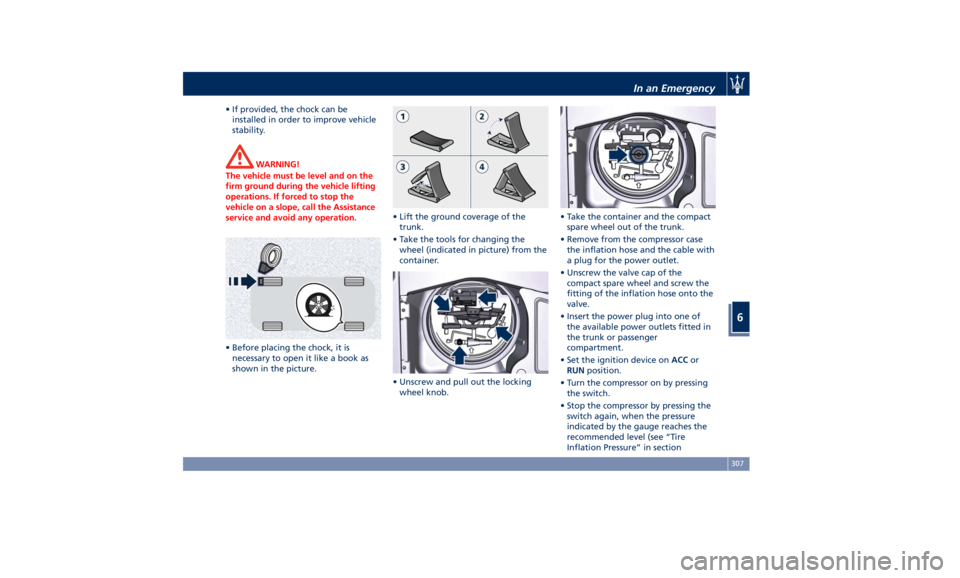
• If provided, the chock can be
installed in order to improve vehicle
stability.
WARNING!
The vehicle must be level and on the
firm ground during the vehicle lifting
operations. If forced to stop the
vehicle on a slope, call the Assistance
service and avoid any operation.
• Before placing the chock, it is
necessary
to open
it like a book as
shown in the picture. • Lift the ground coverage of the
trunk.
• Take the tools for changing the
wheel (indicated in picture) from the
container.
• Unscrew and pull out the locking
wheel knob. • Take the container and the compact
spare wheel out of the trunk.
• Remove from the compressor case
the inflation hose and the cable with
a plug for the power outlet.
• Unscrew the valve cap of the
compact spare wheel and screw the
fitting of the inflation hose onto the
valve.
• Insert the power plug into one of
the available power outlets fitted in
the trunk or passenger
compartment.
• Set the ignition device on ACC or
RUN position.
• Turn the compressor on by pressing
the switch.
• Stop the compressor by pressing the
switch again, when the pressure
indicated by the gauge reaches the
recommended level (see “Tire
Inflation Pressure” in sectionIn an Emergency
6
307
Page 312 of 384

“Features and Specifications”) and
screw the cap on the compact spare
wheel valve.
CAUTION!
• In order to obtain a more accurate
reading, the compressor should be
switched off when checking the tire
pressure of the compact spare wheel
on the pressure gauge.
• Do not run the compressor for more
than 20 minutes: there is a risk it
could overheat. Also, prolonged
power absorption may discharge the
battery, subsequently preventing the
engine from starting.
• The compressor has been designed
exclusively to inflate compact spare wheels; do not use it to inflate air
mattresses, floatation devices, etc.
• Remove the center cover of the
wheel
rim (if equipped) levering into
the provided groove on the outer
ledge of the cover.
• Fit the adapter on the wrench.
Extend the wrench as shown, then
loosen by approximately one turn,
the five bolts on the wheel to be
changed.
• Place the jack near the wheel to be
changed as illustrated.
• Make sure that the head of the jack
is correctly inserted in one of the
slots beneath the rocker panel.
WARNING!
• The jack should be used on level firm
ground wherever possible. • It is recommended that the wheels
of the vehicle be chocked, and that
no person should remain in a vehicle
that is being jacked.
• If the vehicle has been stopped on a
slope or an uneven surface, place
chocks or other suitable items in
front of or behind the wheels to
stop the vehicle from moving.
• Never start or run the engine with
the vehicle on a jack.
• No person should place any portion
of their body under a vehicle that is
supported by a jack.
WARNING!
• Never position yourself under a
jacked vehicle.
• Never use the jack to carry out
maintenance or repairs under the
vehicle.
• Turn the jack lever until the wheel is
raised a few
centimeters off the
ground.
• Completely unscrew the five bolts
and remove the wheel. In case a
wheel security stud bolt is installed, it
can only be removed by using the
specific fitting wrench provided withIn an Emergency
6
308
Page 314 of 384

WARNING!
• The spare wheel is narrower than
standard wheels and must only be
used to travel the distance required
to reach a service station, where the
punctured tire can be repaired or
replaced.
• Do not exceed a maximum speed of
50 mph (80 km/h) when using the
compact spare wheel; when this
limit is exceeded, the stability, road
holding and braking of the vehicle
will be compromised. Avoid
accelerating to full speed, heavy
braking and fast cornering.
• The compact spare wheel must be
inflated to the recommended tire
pressure (see “Tire Inflation
Pressure” in section “Features and
Specifications”). • For safety reasons, it is absolutely
forbidden to drive with more than
one compact spare wheel fitted on
the vehicle.
• Snow chains cannot be fitted on the
compact spare wheel.
• The spare wheel can travel a
maximum of 1,800 mi (3.000 km).
To Refit the Standard Wheel with
Repair
ed or Replaced Tire
• Following the procedure and the
caution described above, raise the
vehicle and remove the compact
spare wheel reusing the supplied
wrench with adapter, suitably
extended.
• Fit the standard wheel with repaired
or replaced tire.
• Tighten the original bolts on the
wheel.
• Lower the vehicle and remove the
jack.
• Fully tighten the bolts, alternately
tightening diametrically opposite. WARNING!
Observe the tightening torque for the
bolts securing the wheels (72 ± 7 lbf·ft
/ 98 ± 10 Nm). Check the correct
tightening torque as soon possible
contacting an Authorized Maserati
Dealer.
• Reassemble the center cover (if
equipped)
on the wheel rim.
Once finished:
• completely deflate the compact
spare wheel by pressing on the valve
with the overhang of the valve cap;
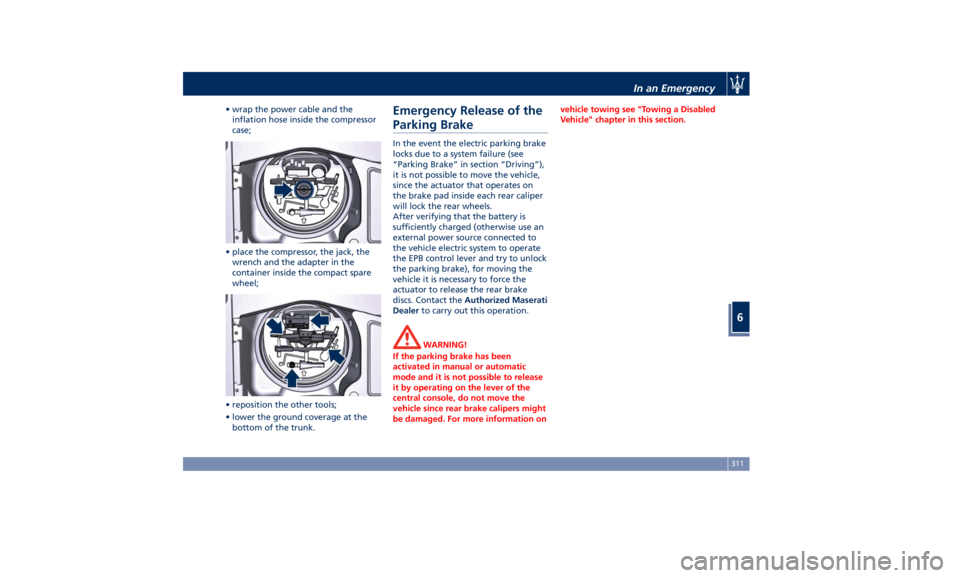
• place the compact spare wheel and
tool container in the trunk;
• fix everything in place with the
locking knob;In an Emergency
6
310
Page 315 of 384

• wrap the power cable and the
inflation hose inside the compressor
case;
• place the compressor, the jack, the
wrench and the adapter in the
container inside the compact spare
wheel;
• reposition the other tools;
• lower the ground coverage at the
bottom of the trunk. Emergency Release of the
Parking Brake In the event the electric parking brake
locks due to a system failure (see
“Parking Brake” in section “Driving”),
it is not possible to move the vehicle,
since the actuator that operates on
the brake pad inside each rear caliper
will lock the rear wheels.
After verifying that the battery is
sufficiently charged (otherwise use an
external power source connected to
the vehicle electric system to operate
the EPB control lever and try to unlock
the parking brake), for moving the
vehicle it is necessary to force the
actuator to release the rear brake
discs. Contact the Authorized Maserati
Dealer to carry out this operation.
WARNING!
If the parking brake has been
activated in manual or automatic
mode and it is not possible to release
it by operating on the lever of the
central console, do not move the
vehicle since rear brake calipers might
be damaged. For more information on vehicle towing see "Towing a Disabled
Vehicle" chapter in this section.
In an Emergency
6
311
Page 325 of 384

Interval running coupons: every 12,500 mi (20,000 km)
or 1 year
Service coupons 1° 2° 3° 4°
5° 6°
Main operations Available Pre-Paid Maintenance
Program
Correct operation and reliability of the seats and seat belts IIIIII
Pollen filter RRR
Windshield fluid level - Windshield washer IIIIII
Headlight leveling IIIIII
Controls and adjustment systems in general, hinges, doors,
engine compartment lid and luggage compartment III
Condition of leather interiors III
I = Inspect and carry out any other necessary operation.
R = Replace.
Periodic Maintenance Every 600 mi (1,000 km) or before
long journeys
Check:
• engine coolant;
• brake fluid;
• windshield washer fluid level;
• tire inflation pressure and condition;
• operation of lighting system
(headlights, direction indicators,
hazard warning flashers, etc.); • operation of windshield
washer/wiper system and wear of
windshield wiper blades.
Every 1,900 mi (3,000 km)
Check and top up, if required, the
engine oil level.
WARNING!
California Proposition 65
Operating, servicing and maintaining
a passenger vehicle or off-road vehicle
can expose you to chemicals including
such as, engine exhaust, carbon monoxide, phthalates and lead, that
which are known to the State of
California to cause cancer and birth
defects or other reproductive harm. To
minimize exposure, avoid breathing
exhaust, do not idle the engine except
as necessary, service your vehicle in a
well-ventilated area and wear gloves
or wash your hands frequently when
servicing your vehicle. For more
information go to:
www.P65Warnings.ca.gov/passenger-
vehicleMaintenance and Care
7
321
Page 380 of 384

Spare parts service
Genuine Parts ..............13
Scheduled Maintenance .......13
Spare Parts Service .............13
SRS (Supplemental Restraint
System) ....................64
Start&Stop System ........... .210
Occupant Safety Function .... .212
Start&Stop Active Indicator . . . .148
Start&Stop Disable Indicator . . . .167
Start&Stop Failure Indicator
Light ................... .167
Start&Stop Function Disabling
Indicator ................ .212
Start&Stop Menu .......... .158
Start&Stop System Failure .... .214
Start the Engine
Engine Start Failure ......... .209
Engine Turn Off ........... .210
Steering Wheel
Heated Steering Wheel ...... .106
Phone and Voice Controls on
Steering Wheel ............ .204
Sunroof
Pinch Protect Feature ....... .137
Slide Opening Sunroof ....... .137
Sunroof Maintenance ....... .138
Venting Sunroof ........... .137
Sunshades ................. .136
Power Sunshades ............47
Sun Visors ................. .130
Surround View Camera System ....80
Symbols ....................14 Danger Symbols .............14
Symbols of Prohibitions and
Compulsory Measures .........14
TCS (Traction Control System) .... .240
Technical Data .............. .364
Telltales
Telltales on Speedometer ..... .146
Telltales on Tachometer ...... .148
Warning/Indicator Lights of Set
Modes/Functions on Display . . . .163
TFT Display: Menus and Settings . . .150
Tires
Change a Tire ............. .306
Compact spare tire ......... .289
Department of Transportation
Uniform Tire Quality Grades . . . .285
General Information ........
.281
Inflation
Pressure .......... .370
Punctured Tire, use ......... .306
Replacement Tires .......... .287
Tire Pressure .............. .286
Tire Pressure Checkup ....... .286
Tire Safety Information ...... .281
TPMS - Tire Pressure Monitoring
System .................. .289
Winter Tires .............. .288
ToolKit................... .304
Towing
Towing a Disabled Vehicle .... .315
Towing the Vehicle ......... .315
Vehicle Towing Conditions .... .315
TPMS System ............... .289 Tire Pressure Low Warning .... .291
TPMS Deactivation ......... .293
Traffic Sign Assist - TSA ........ .279
Transmission, Automatic ....... .214
Automatic Transmission Lever . . .215
Automatic Transmission Range . .218
Malfunction and Overheating
Conditions ............... .222
Transmission Manual Release of P
(Park) Position ............ .312
Transmitter, Key fob RKE
Preventing Inadvertent Locking of
Key fob RKE Transmitter Inside the
Vehicle ...................43
Trunk
Power Trunk Lid/Hand Free
(optional) .................50
Trunk Safety ...............54
Trunk Lid
Power Trunk Lid/Hand Free
(optional) .................50
Trunk Lid Emergency Release from
inside the Trunk .............53
Trunk Lid Operation ..........49
Updating ....................9
Vehicle Identification Number (VIN) .18
Vehicle Stored for Long Periods . . .355
Voice Commands ............ .205
Warning icons .................8
Warnings when Driving .........15Index
9 376