Page 445 of 555

Maintenance
14
7
Maintenance Under Severe Usage Conditions - Turbo Models
The following items must be serviced more frequently on cars normally used under severe driving conditions. Refer
to the chart below for the appropriate maintenance intervals.
R : Replace I : Inspect and, after inspection, clean, adjust, repair or replace if neces\
sary
MAINTENANCE ITEMMAINTENANCE
OPERATIONMAINTENANCE INTERVALSDRIVING
CONDITION
Engine oil and
engine oil filterTheta II 2.0L T-GDIREvery 5,000 km (3,000 miles) or 6 monthsA, B, C, D, E,
F, G, H, I, J, K
Lambda II PE 3.3L T-GDIREvery 5,000 km (3,000 miles) or 6 monthsA, B, C, D, E,
F, G, H, I, J, K
Air cleaner filterIMore frequentlyC, E
Spark plugs RMore frequentlyA, B, F, G, H, I, K
Automatic transaxle fluidREvery 100,000 km (60,000 miles) A, C, D, E,
F, G, H, I, J
Front brake disc/pads, calipersIMore frequentlyC, D, E, G, H
Rear brake disc/padsIMore frequentlyC, D, E, G, H
Parking brakeIMore frequentlyC, D, G, H
Steering gear box, linkage & boots/
Lower arm ball joint, upper arm ball jointIMore frequentlyC, D, E, F, G
Page 466 of 555

735
Maintenance
BATTERY
Battery replacement
The battery is in the trunk under the
compartment cover.
When replacing the battery, disconnect
the negative (-) cable (1) and remove
the positive (+) battery fuse box (2).
Remove the battery mounting brack-
et (3).
For best battery service
Keep the battery securely mount-ed.
Keep the battery top clean and dry.
Keep the terminals and connec- tions clean, tight, and coated with
petroleum jelly or terminal grease.
Rinse any spilled electrolyte from the battery immediately with a
solution of water and baking soda.
If the vehicle is not going to be used for an extended time, discon-
nect the battery cables.
OCK077031
WARNING
- Touching metal surfaces
in the trunk under the
compartment cover
Do not touch metal surfaces in
the trunk under the compart-
ment cover while the engine is
operating or hot. Doing so could
result in serious personal injury.
Turn the engine off and wait
until it cools down or wear
gloves to replace the battery
from the luggage room.
Page 478 of 555

747
Maintenance
5. Maximum permissible inflationpressure
This number is the greatest amount of
air pressure that should be put in the
tire. Do not exceed the maximum per-
missible inflation pressure. Refer to
the Tire and Loading Information label
for recommended inflation pressure.
6. Maximum load rating
This number indicates the maximum
load in kilograms and pounds that can
be carried by the tire. When replacing
the tires on the vehicle, always use a
tire that has the same load rating as
the factory installed tire.
7. Uniform tire quality grading
Quality grades can be found where
applicable on the tire sidewall
between tread shoulder and maxi-
mum section width.
For example:
TREADWEAR 440
TRACTION A
TEMPERATURE A Tread wear
The tread wear grade is a compara-
tive rating based on the wear rate of
the tire when tested under controlled
conditions on a specified govern-
ment test course. For example, a tire
graded 150 would wear one-and-a-
half times (1½) as well on the gov-
ernment course as a tire graded 100.
The relative performance of tires
depends upon the actual conditions
of their use, however, and may
depart significantly from the norm
due to variations in driving habits,
service practices and differences in
road characteristics and climate.
Tires degrade over time, even when
they are not being used. Regardless
of the remaining tread, we recom-
mend that tires be replaced after
approximately six (6) years of normal
service. Heat caused by hot climates
or frequent high loading conditions
can accelerate the aging process.
These grades are molded on the
side-walls of passenger vehicle tires.
The tires available as standard or
optional equipment on your vehicles
may vary with respect to grade.
Page 508 of 555

777
Maintenance
LIGHT BULBS
Bulb replacement precaution
Please keep extra bulbs on hand
with appropriate wattage ratings in
case of emergencies.
Refer to “Bulb Wattage” in chapter 8.
When changing lamps, first turn off
the engine at a safe place, firmly
apply the parking brake and detach
the battery’s negative (-) terminal.
Use only bulbs of the specifiedwattage. net-work failure
The headlamp, taillight, and fog light
may light up when the head lamp
switch is turned ON, and not light up
when the taillight or for light switch is
turned ON. This may be cause by
network failure or vehicle electrical
control system malfunction. If there is
a problem, we recommend the sys-
tem be serviced by an authorized Kia
dealer.
trical control system stabilization
A normally functioning lamp may
flicker momentarily. This momentary
occurrence is due to the stabilization
function of the vehicle's electrical
control system. If the lamp stops
flickering after a few moments, the
vehicle does not require service.
However, if the lamp goes out after
the momentary flickering, or the flick-
ering continues, we recommend the
system be serviced by an authorized
Kia dealer.
WARNING- Working on the lights
Prior to working on the light,
firmly apply the parking brake,
ensure that the ignition switch
is turned to the LOCK position
and turn off the lights to avoid
sudden movement of the vehi-
cle burns to your skin or fin-
gers, or an electric shock.
CAUTION -Light replace-
ment
Be sure to replace the burned- out bulb with one of the samewattage rating. Otherwise, itmay cause damage to the fuseor electric wiring system.
CAUTION -Headlamp
Lens
To prevent damage, do notclean the headlamp lens withchemical solvents or strongdetergents.
Page 512 of 555
781
Maintenance
Side marker bulb replacement
(Headlamp Type A)
If the side marker (1) does not oper-
ate, have the vehicle checked by an
authorized Kia dealer.
A skilled technician should check or
repair the side marker, for it may
damage related parts of the vehicle.
Position lamp + DRL (LED
type) bulb replacement
(Headlamp Type A)
If the position lamp + DRL (LED) (1)
does not operate, have the vehicle
checked by an authorized Kia dealer.
The LED lamps cannot be replaced
as a single component because they
are part of an integrated unit. The
LED lamps have to be replaced with
the unit.
A skilled technician should check or
repair the position lamp + DRL
(LED), for it may damage related
parts of the vehicle.
Headlamp (Low/High beam)
bulb replacement (Headlamp
Type A)
1. Remove the service cover clip onthe wheel housing.
OCK077101L
■Head lamp - Type A
OCK077073
■Head lamp - Type A
OCK077074
■Head lamp - Type A
Page 513 of 555

Maintenance
82
7
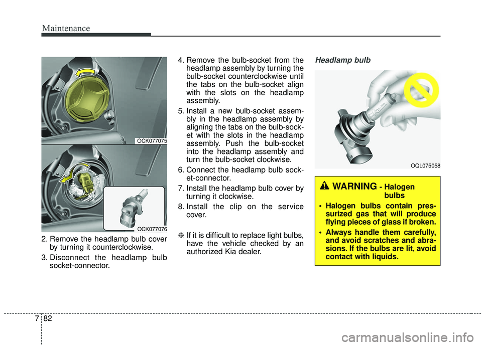
2. Remove the headlamp bulb cover
by turning it counterclockwise.
3. Disconnect the headlamp bulb socket-connector. 4. Remove the bulb-socket from the
headlamp assembly by turning the
bulb-socket counterclockwise until
the tabs on the bulb-socket align
with the slots on the headlamp
assembly.
5. Install a new bulb-socket assem- bly in the headlamp assembly by
aligning the tabs on the bulb-sock-
et with the slots in the headlamp
assembly. Push the bulb-socket
into the headlamp assembly and
turn the bulb-socket clockwise.
6. Connect the headlamp bulb sock- et-connector.
7. Install the headlamp bulb cover by turning it clockwise.
8. Install the clip on the service cover.
❈ If it is difficult to replace light bulbs,
have the vehicle checked by an
authorized Kia dealer.
Headlamp bulb
OCK077075
OCK077076
OQL075058
WARNING- Halogen
bulbs
Halogen bulbs contain pres- surized gas that will produce
flying pieces of glass if broken.
Always handle them carefully, and avoid scratches and abra-
sions. If the bulbs are lit, avoid
contact with liquids.
Page 516 of 555
785
Maintenance
Rear turn signal lamp (LED
type) bulb replacement
If the rear turn signal lamp (LED) (1),
does not operate, have the vehicle
checked by an authorized Kia dealer.
The LED lamps cannot be replaced
as a single component because they
are part of an integrated unit. The
LED lamps have to be replaced with
the unit.
A skilled technician should check or
repair the rear turn signal lamp
(LED), for it may damage related
parts of the vehicle.
Rear turn signal lamp (bulb
type) bulb replacement
1. Open the liftgate.
2. Open the service cover.
OCK078087NOCK077080
OCK077081
OCK077082
OCK077055
Page 517 of 555
Maintenance
86
7
3. Loosen the light assembly retain-
ing screws with a cross-tip screw-
driver or spanner.
4. Remove the rear combination lamp assembly from the body of
the vehicle.
5. Disconnect the rear combination lamp connector.
6. Remove the socket from theassembly by turning the socket
counterclockwise until the tabs on
the socket align with the slots on
the assembly.
7. Remove the bulb from the socket by pressing it in and rotating it
counterclockwise until the tabs on
the bulb align with the slots in the
socket. Pull the bulb out of the
socket.
8. Insert a new bulb by inserting it into the socket and rotating it until
it locks into place. 9. Install the socket in the assembly
by aligning the tabs on the socket
with the slots in the assembly.
Push the socket into the assembly
and turn the socket clockwise.
10. Install the rear combination lamp assembly to the body of the vehi-
cle.
11. Install the service cover.
OCK077056