Page 230 of 455

493
Features of your vehicle
✽ ✽NOTICE
If you want to defrost and defog the
front windshield, refer to
“Windshield defrosting and defog-
ging” in this section.
Rear window defroster
The defroster heats the window to
remove frost, fog and thin ice from
the rear window, while the v ehicle is
in the ready ( ) mode. To activate the rear window
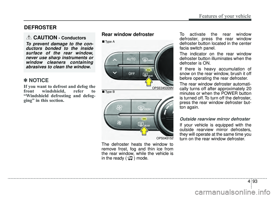
defroster, press the rear window
defroster button located in the center
facia switch panel.
The indicator on the rear window
defroster button illuminates when the
defroster is ON.
If there is heavy accumulation of
snow on the rear window, brush it off
before operating the rear defroster.
The rear window defroster automati-
cally turns off after approximately 20
minutes or when the POWER button
is turned off. To turn off the defroster,
press the rear window defroster but-
ton again.
Outside rearview mirror defroster
If your vehicle is equipped with the
outside rearview mirror defrosters,
they will operate at the same time you
turn on the rear window defroster.
DEFROSTER
CAUTION- Conductors
To prevent damage to the con-
ductors bonded to the insidesurface of the rear window,never use sharp instruments orwindow cleaners containingabrasives to clean the window.
OPSE045309N
OPS043152
■ Type B
■Type A
Page 233 of 455

Features of your vehicle
96
4
✽ ✽
NOTICE
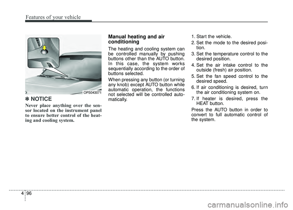
Never place anything over the sen-
sor located on the instrument panel
to ensure better control of the heat-
ing and cooling system.
Manual heating and air
conditioning
The heating and cooling system can
be controlled manually by pushing
buttons other than the AUTO button.
In this case, the system works
sequentially according to the order of
buttons selected.
When pressing any button (or turning
any knob) except AUTO button while
automatic operation, the functions
not selected will be controlled auto-
matically. 1. Start the vehicle.
2. Set the mode to the desired posi-
tion.
3. Set the temperature control to the desired position.
4. Set the air intake control to the outside (fresh) air position.
5. Set the fan speed control to the desired speed.
6. If air conditioning is desired, turn the air conditioning system on.
7. If heater is desired, press the HEAT button.
Press the AUTO button in order to
convert to full automatic control of
the system.
OPS043071
Page 236 of 455
499
Features of your vehicle
Defrost mode (A, D)
Most of the air flow is directed to the
windshield with a small amount of air
directed to the side window defrosters.Instrument panel vents
The outlet port can be opened or
closed separately using the thumb-
wheel.
Also, you can adjust the direction of
air delivered from these vents using
the vent control lever as shown.
Temperature control
A
The temperature will increase to the
maximum (90°F(32°C)) by pushing
the button ( ).
OPS043059
OPSE045314N
OPS043169
■
Type B
■Type A
OPSE045312N
OPS043171
■Type B
■Type A
Page 409 of 455

751
Maintenance
Instrument panel (Driver’s side fuse panel)
Fuse Name Fuse ratingCircuit Protected
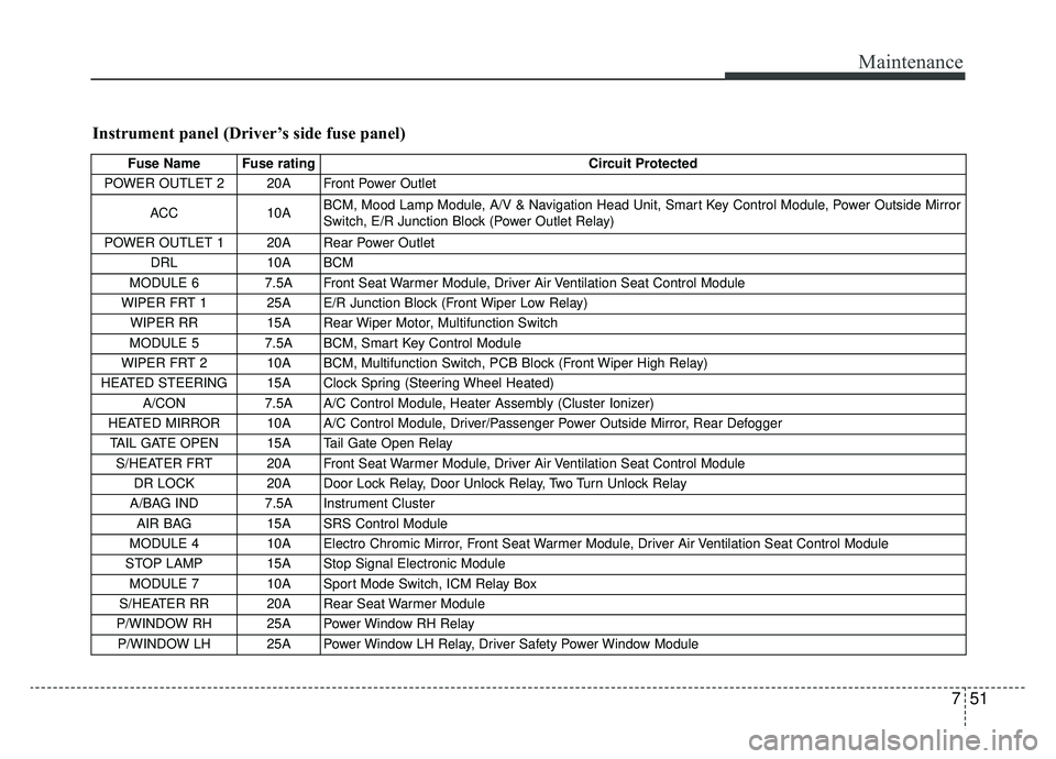
POWER OUTLET 2 20A Front Power Outlet
ACC 10A BCM, Mood Lamp Module, A/V & Navigation Head Unit, Smart Key Control Module, Power Outside Mirror
Switch, E/R Junction Block (Power Outlet Relay)
POWER OUTLET 1 20A Rear Power Outlet DRL 10A BCM
MODULE 6 7.5A Front Seat Warmer Module, Driver Air Ventilation Seat Control Module
WIPER FRT 1 25A E/R Junction Block (Front Wiper Low Relay) WIPER RR 15A Rear Wiper Motor, Multifunction Switch
MODULE 5 7.5A BCM, Smart Key Control Module
WIPER FRT 2 10A BCM, Multifunction Switch, PCB Block (Front Wiper High Relay)
HEATED STEERING 15A Clock Spring (Steering Wheel Heated) A/CON 7.5A A/C Control Module, Heater Assembly (Cluster Ionizer)
HEATED MIRROR 10A A/C Control Module, Driver/Passenger Power Outside Mirror, Rear Defogger TAIL GATE OPEN 15A Tail Gate Open Relay S/HEATER FRT 20A Front Seat Warmer Module, Driver Air Ventilation Seat Control Module DR LOCK 20A Door Lock Relay, Door Unlock Relay, Two Turn Unlock Relay
A/BAG IND 7.5A Instrument Cluster AIR BAG 15A SRS Control Module
MODULE 4 10A Electro Chromic Mirror, Front Seat Warmer Module, Driver Air Ventilation Seat Control Module
STOP LAMP 15A Stop Signal Electronic Module MODULE 7 10A Sport Mode Switch, ICM Relay Box
S/HEATER RR 20A Rear Seat Warmer Module
P/WINDOW RH 25A Power Window RH Relay P/WINDOW LH 25A Power Window LH Relay, Driver Safety Power Window Module
Page 450 of 455

Index
4I
Explanation of scheduled maintenance items . . . . . . . 7-13
Exterior overview . . . . . . . . . . . . . . . . . . . . . . . . . . . . . . 2-2
Fuses . . . . . . . . . . . . . . . . . . . . . . . . . . . . . . . . . . . . \
. . . 7-45Fuse/relay panel description. . . . . . . . . . . . . . . . . . . 7-50
Inner panel fuse replacement . . . . . . . . . . . . . . . . . . 7-47
Motor compartment fuse replacement . . . . . . . . . . . 7-48
Gross vehicle weight. . . . . . . . . . . . . . . . . . . . . . . . . . . . 8-3
Hood . . . . . . . . . . . . . . . . . . . . . . . . . . . . . . . . . . . . \
. . . 4-22 Closing the hood . . . . . . . . . . . . . . . . . . . . . . . . . . . 4-22
Opening the hood . . . . . . . . . . . . . . . . . . . . . . . . . . . 4-22
If the vehicle overheats . . . . . . . . . . . . . . . . . . . . . . . . . . 6-8
If the vehicle will not start . . . . . . . . . . . . . . . . . . . . . . . 6-4 If vehicle doesn’t turn over or turns over slowly . . . . 6-4
If you have a flat tire (with Tire Mobility Kit). . . . . . . 6-14 Components of the Tire Mobility Kit . . . . . . . . . . . 6-16
Distributing the sealant . . . . . . . . . . . . . . . . . . . . . . 6-18 Introduction . . . . . . . . . . . . . . . . . . . . . . . . . . . . . . . 6-14
Technical Data . . . . . . . . . . . . . . . . . . . . . . . . . . . . . 6-20
Using the Tire Mobility Kit . . . . . . . . . . . . . . . . . . . 6-17
In case of an emergency while driving . . . . . . . . . . . . . . 6-3 If the vehicle stalls at a crossroad or crossing . . . . . . 6-3
If vehicle stalls while driving . . . . . . . . . . . . . . . . . . . 6-3
If you have a flat tire while driving . . . . . . . . . . . . . . 6-3
Instrument cluster . . . . . . . . . . . . . . . . . . . . . . . . . . . . . 4-40 Gauges . . . . . . . . . . . . . . . . . . . . . . . . . . . . . . . . . . . 4-\
42
Instrument cluster control . . . . . . . . . . . . . . . . . . . . 4-41
LCD display control . . . . . . . . . . . . . . . . . . . . . . . . . 4-41
Reduction gear shift indicator . . . . . . . . . . . . . . . . . 4-45
Instrument panel overview . . . . . . . . . . . . . . . . . . . . . . . 2-5
Interior features. . . . . . . . . . . . . . . . . . . . . . . . . . . . . . 4-118 Cargo area cover. . . . . . . . . . . . . . . . . . . . . . . . . . . 4-126
Clothes hanger . . . . . . . . . . . . . . . . . . . . . . . . . . . . 4-124
Cup holder . . . . . . . . . . . . . . . . . . . . . . . . . . . . . . . 4-118
Floor mat anchor(s) . . . . . . . . . . . . . . . . . . . . . . . . 4-124
Luggage net holder. . . . . . . . . . . . . . . . . . . . . . . . . 4-125
Power outlet . . . . . . . . . . . . . . . . . . . . . . . . . . . . . . 4-123
Rear seat warmer . . . . . . . . . . . . . . . . . . . . . . . . . . 4-122
Seat air ventilation . . . . . . . . . . . . . . . . . . . . . . . . . 4-121
Seat warmer . . . . . . . . . . . . . . . . . . . . . . . . . . . . . . 4-119
Sunvisor . . . . . . . . . . . . . . . . . . . . . . . . . . . . . . . . . 4-119
Interior light . . . . . . . . . . . . . . . . . . . . . . . . . . . . . . . . . 4-90 Glove box lamp . . . . . . . . . . . . . . . . . . . . . . . . . . . . 4-92
Interior lamp auto cut . . . . . . . . . . . . . . . . . . . . . . . . 4-90
Luggage room lamp . . . . . . . . . . . . . . . . . . . . . . . . . 4-92
F
G
H
I
Page:
< prev 1-8 9-16 17-24