2019 KIA RIO HATCHBACK instrument panel
[x] Cancel search: instrument panelPage 199 of 503

4121
Features of your vehicle
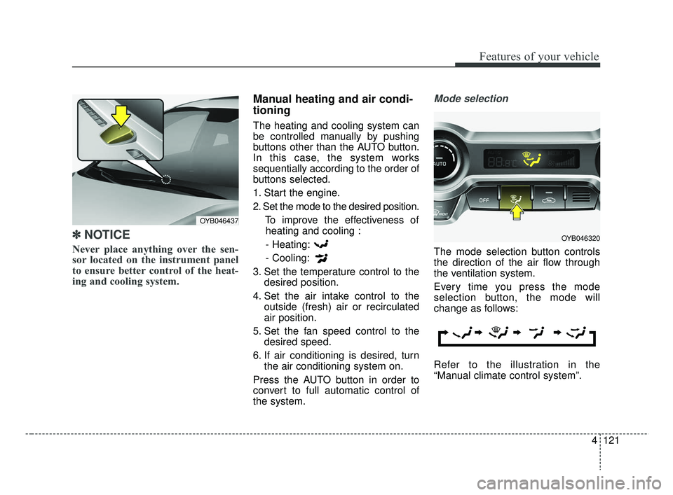
✽ ✽NOTICE
Never place anything over the sen-
sor located on the instrument panel
to ensure better control of the heat-
ing and cooling system.
Manual heating and air condi-
tioning
The heating and cooling system can
be controlled manually by pushing
buttons other than the AUTO button.
In this case, the system works
sequentially according to the order of
buttons selected.
1. Start the engine.
2. Set the mode to the desired position.
To improve the effectiveness ofheating and cooling :
- Heating:
- Cooling:
3. Set the temperature control to the desired position.
4. Set the air intake control to the outside (fresh) air or recirculated
air position.
5. Set the fan speed control to the desired speed.
6. If air conditioning is desired, turn the air conditioning system on.
Press the AUTO button in order to
convert to full automatic control of
the system.
Mode selection
The mode selection button controls
the direction of the air flow through
the ventilation system.
Every time you press the mode
selection button, the mode will
change as follows:
Refer to the illustration in the
“Manual climate control system”.
OYB046437
OYB046320
SC CAN (ENG) 4.QXP 7/18/2018 5:52 PM Page 121
Page 201 of 503

4123
Features of your vehicle
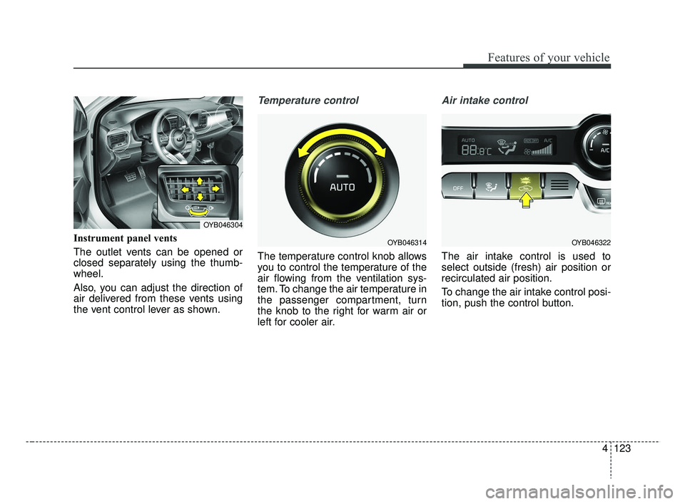
Instrument panel vents
The outlet vents can be opened or
closed separately using the thumb-
wheel.
Also, you can adjust the direction of
air delivered from these vents using
the vent control lever as shown.
Temperature control
The temperature control knob allows
you to control the temperature of the
air flowing from the ventilation sys-
tem. To change the air temperature in
the passenger compartment, turn
the knob to the right for warm air or
left for cooler air.
Air intake control
The air intake control is used to
select outside (fresh) air position or
recirculated air position.
To change the air intake control posi-
tion, push the control button.
OYB046304
OYB046322OYB046314
SC CAN (ENG) 4.QXP 7/18/2018 5:52 PM Page 123
Page 434 of 503

Maintenance
62
8
Fuse NameFuse ratingCircuit Protected
DOOR LOCK20ATail Gate Unlock Relay, Door Lock/Unlock Relay, Two Turn Unlock Relay
POWER OUTLET20APower Outlet
SAFETY P/WINDOW25ADriver Safety Power Window Module
STOP LAMP15AStop Signal Electronic Module
T/SIGNAL LAMP15ABCM (Body Control Module), SLM (Seat Belt & Lighting Module)
C/LIGHTER20ACigarette Lighter
HEATED
MIRROR10ADriver Power Outside Mirror, Passenger Power Outside Mirror, Air Conditioner Control Module, ECM
(Engine Control Module)/PCM (Power train Control Module)
DRL210ABCM (Body Control Module)
P/WINDOW RH25APower Window Main Switch, Passenger Power Window Switch
S/HEATER20AFront Seat Warmer Control Module
DRL110A-
START7.5AWith Immobilizer : ECM (Engine Control Module)/PCM (Power train Control Module), Engine Room
Junction Block(Start Relay), Smart Key Control Module
Without Immobilizer : Burglar Alarm Relay
TAIL LAMP RH7.5AHead Lamp Right Handle side, Rear Combination Lamp (OUT) Right Handle side, License Lamp Right
Handle side, Rear Combination Lamp (IN) Right Handle side, Illumination (+)
MODULE210AForward Collision-Avoidance Assist (FCA) Unit, Crash Pad Switch
Instrument panel (Driver’s side fuse panel)
SC CAN (ENG) 8.qxp 7/18/2018 5:34 PM Page 62
Page 439 of 503

867
Maintenance
Engine room compartment fuse panel
Fuse NameFuse ratingCircuit Protected
MDPS80AMDPS (Motor Driven Power Steering) Unit
ALT150AFuse - ABS1, BAS2, BLOWER, REAR HEATED
REAR HEATED40AInstrument Panel Junction Block (Rear Defogger Relay)
ABS140AESC (Electronic Stability Control) Module, Multipurpose Check Connector
ABS240AESC (Electronic Stability Control) Module
BLOWER40ABlower Relay
WIPER10AFront Wiper Motor, Multifunction Switch, Wiper Low Relay
ECU415AECM (Engine Control Module)/PCM (Power train Control Module)
SENSOR10AOil Control Valve #1/#2, Cooling Fan1/2 Relay, Oxygen Sensor (Up), Oxygen Sensor (Down), Variable
Intake Solenoid Valve, Air Conditioner Relay, Purge Control Solenoid Valve, Canister Close Valve
ECU215AECM (Engine Control Module)/PCM (Power train Control Module)
ECU320AECM (Engine Control Module)/PCM (Power train Control Module)
HEAD LAMP RH10AHead Lamp Right Handle side
HEAD LAMP LH10AHead Lamp Left Handle side
IGN COIL20AIgnition Coil #1~#4, Condenser
ECU515AECM (Engine Control Module)/PCM (Power train Control Module), Fuel Pump Relay
SC CAN (ENG) 8.qxp 7/18/2018 5:34 PM Page 67
Page 440 of 503

Maintenance
68
8
Fuse NameFuse ratingCircuit Protected
B/UP LAMP10ABack-Up Lamp Switch
B+140AInstrument Panel Junction Block (Fuse - DRL2, FOGLAMP FRONT, STOP LAMP, MODULE6, Power
Connector (AUDIO, ROOM LAMP))
B+250AInstrument Panel Junction Block (Fuse - IMMO, SMART KEY, BRAKE SWITCH, SAFETY P/WINDOW,
S/HEATER, SUNROOF, Power Window Relay)
IG240AIgnition Switch, IG2 Relay, Start Relay
COOLING FAN40ACooling Fan1/2 Relay
ECU130AFuse - ECU3, ECU4, Main Relay
HEAD LAMP20AHead Lamp Relay
H/LAMP HI20AWith CANADA DRL : SLM(Seat Belt & Lighting Module) or BCM(Body Control Module)
Without CANADA DRL : Head Lamp HI Relay
FUEL PUMP20AFuel Pump Relay
HORN15AHorn Relay/ Burglar Alarm Horn Relay
A/CON10AAir Conditioner Relay
AMS10ABattery Sensor
B+340AInstrument Panel Junction Block (Fuse - T/SIGNAL LAMP, DOOR LOCK, Tail Lamp Relay)
IG140AIgnition Switch, IG1 Relay, ACC Relay
POWER OUTLET40AInstrument Panel Junction Block (Power Outlet Relay)
SC CAN (ENG) 8.qxp 7/18/2018 5:34 PM Page 68
Page 498 of 503

I5
Index
Distributing the sealant ..............................................7-23
Introduction ................................................................7-18
Notes on the safe use of the Tire Mobility Kit ..........7-19
Technical data ............................................................7-25
Using the Tire Mobility Kit ........................................7-21
In case of an emergency while driving............................7-3 If engine stalls while driving ........................................7-3
If the engine stalls at a crossroad or crossing ..............7-3
If you have a flat tire while driving ..............................7-3
Instrument cluster ..........................................................4-57 Gauges ........................................................................\
4-59
Instrument Cluster Control ........................................4-58
LCD window control ..................................................4-58
Transmission shift indicator........................................4-62
Instrument panel overview ..............................................2-6
Interior features............................................................4-136 Clothes hanger ..........................................................4-140
Covering shelf (for 5 door) ......................................4-142
Cup holder ................................................................4-136
Floor mat anchor(s) ..................................................4-141
Power outlet ..............................................................4-138
Seat warmer ..............................................................4-137
Shopping bag holder ................................................4-141
Sunvisor ....................................................................4-13\
6
USB charger ..............................................................4-139
Interior light ................................................................4-103 Automatic turn off function ......................................4-103
Glove box lamp ........................................................4-106 Luggage room lamp ..................................................4-106
Map lamp ..................................................................4-103
Room lamp................................................................4-104
Vanity mirror lamp ....................................................4-107
Interior overview ............................................................2-5
Key positions ..................................................................6-6 Ignition switch position ................................................6-6
Keys ........................................................................\
........4-4 Key operations ..............................................................4-4
Record your key number ..............................................4-4
LCD windows ................................................................4-64 LCD modes (for type B cluster) ................................4-69
Over view ....................................................................4-64\
Service mode ..............................................................4-70
Trip information (Trip computer) ..............................4-64
User settings mode (for type B cluster) ......................4-70
Light bulbs ....................................................................8-70\
Back-up lamp bulb replacement (for 4 door) ............8-92
Back-up lamp bulb replacement (for 5 door) ............8-86
Bulb replacement precaution ....................................8-70
Daytime running lamp (Bulb type) bulb replacement ..............................................................8-81
K
L
SC CAN (ENG) Index.qxp 7/18/2018 5:31 PM Page 5