Page 420 of 491
7-46
Maintenance
Temperature - A, B & C
The temperature grades are A (the
highest), B and C representing the
tire’s resistance to the generation of
heat and its ability to dissipate heat
when tested under controlled condi-
tions on a specified indoor laboratory
test wheel.
Sustained high temperature can
cause the material of the tire to
degenerate and reduce tire life, and
excessive temperature can lead to
sudden tire failure. Grade C
responds to a level of performance
which all passenger car tires must
meet under the Federal Motor
Vehicle Safety Standard No. 109.
Grades B and A represent higher
levels of performance on the labora-
tory test wheel than the minimum
required by law.
Tire Terminology and
Definitions
Air Pressure
The amount of air inside the tire
pressing outward on the tire. Air
pressure is expressed in pounds per
square inch (psi) or kilopascal (kPa).
Accessory Weight
This means the combined weight of
optional accessories. Some exam-
ples of optional accessories are
automatic transmission, power
seats, and air conditioning.
Aspect Ratio
The relationship of a tire's height to
its width.
Belt
A rubber coated layer of cords that is
located between the plies and the
tread. Cords may be made from steel
or other reinforcing materials.
The temperature grade for this
tire is established for a tire that
is properly inflated and not
overloaded. Excessive speed,
under-inflation, over-inflation,
or excessive loading, either
separately or in combination,
can cause heat build-up and
possible sudden tire failure.
This may cause loss of vehicle
control resulting in an accident.
WARNING
Page 424 of 491
7-50
Maintenance
Snow Tires
If you equip your car with snow tires,
they should be the same size and
have the same load capacity as the
original tires. Snow tires should be
installed on all four wheels; other-
wise, poor handling may result. Snow
tires should carry 4 psi (28 kPa)
more air pressure than the pressure
recommended for the standard tires
on the tire label on the driver’s side of
the center pillar, or up to the maxi-
mum pressure shown on the tire
sidewall, whichever is less. Do not
drive faster than 75 mph (120 km/h)
when your vehicle is equipped with
snow tires.
Radial-Ply Tires
Radial-ply tires provide improved
tread life, road hazard resistance and
smoother high speed ride. The radi-
al-ply tires used on this vehicle are of
belted construction, and are selected
to complement the ride and handling
characteristics of your vehicle.Radial-ply tires have the same load
carrying capacity, as bias-ply or bias
belted tires of the same size, and use
the same recommended inflation
pressure. Mixing of radial-ply tires
with bias-ply or bias belted tires is
not recommended. Any combina-
tions of radial-ply and bias-ply or bias
belted tires when used on the same
vehicle will seriously deteriorate
vehicle handling. The best rule to fol-
low is: Identical pairs of radial-ply
tires should always be used as a set
for the front tires and a set for the
rear tires.
Longer wearing tires can be more
susceptible to irregular tread wear. It
is very important to follow the tire
rotation interval in this chapter to
achieve the tread life potential of
these tires. Cuts and punctures in
radial-ply tires are repairable only in
the tread area, because of sidewall
flexing. Consult your tire dealer for
radial-ply tire repairs.
Low Aspect Ratio Tires
The aspect ratio is lower than 50 on
low aspect ratio tires.
Because low aspect ratio tires are
optimized for handling and braking,
their sidewall is a little stiffer than a
standard tire. Also low aspect ratio
tires tend to be wider and conse-
quently have a greater contact patch
with the road surface. In some
instances they may generate more
road noise compared with standard
tires.
Do not mix bias ply and radial
ply tires under any circum-
stances. This may cause unusu-
al handling characteristics that
may cause loss of vehicle con-
trol resulting in an accident.
WARNING
Page 426 of 491
7-52
Maintenance
F
FU
U S
SE
E S
S
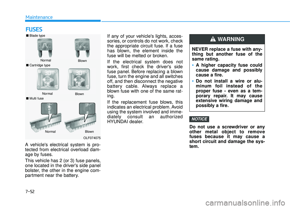
A vehicle's electrical system is pro-
tected from electrical overload dam-
age by fuses.
This vehicle has 2 (or 3) fuse panels,
one located in the driver's side panel
bolster, the other in the engine com-
partment near the battery. If any of your vehicle's lights, acces-
sories, or controls do not work, check
the appropriate circuit fuse. If a fuse
has blown, the element inside the
fuse will be melted or broken.
If the electrical system does not
work, first check the driver's side
fuse panel. Before replacing a blown
fuse, turn the engine and all switches
off, and then disconnect the negative
battery cable. Always replace a
blown fuse with one of the same rat-
ing.
If the replacement fuse blows, this
indicates an electrical problem. Avoid
using the system involved and imme-
diately consult an authorized
HYUNDAI dealer.
Do not use a screwdriver or any
other metal object to remove
fuses because it may cause a
short circuit and damage the sys-
tem.
NOTICE
NEVER replace a fuse with any-
thing but another fuse of the
same rating.
A higher capacity fuse could
cause damage and possibly
cause a fire.
Do not install a wire or alu-
minum foil instead of the
proper fuse - even as a tem-
porary repair. It may cause
extensive wiring damage and
possibly a fire.
WARNING ■Blade type
Normal
■ Cartridge type Blown
Normal
Blown
■ Multi fuse
Normal Blown
OLF074075
Page 431 of 491
7-57
7
Maintenance
Fuse NameFuse RatingProtected Component
MODULE57.5AA/T Shift Lever IND., Electro Chromic Mirror, A/V & Navigation Head Unit,
A/C Control Module, Crash Pad Switch, Front Seat Warmer Module, Audio
MODULE37.5ASport Mode Switch, BCM
SUNROOF120ASunroof Control Module (GLASS)
TAIL GATEOPEN10ATail Gate Relay
P/WINDOW LH25APower Window LH Relay, Driver Safety Power Window Module
MULTI MEDIA15AKeyboard, Audio, A/V & Navigation Head Unit
P/WINDOWRH25APower Window RH Relay
P/SEAT (DRV)25ADriver Seat Manual Switch
SPARE-Spare
MODULE47.5ABlind-Spot Collision Warning Unit LH/RH, Stop Lamp Switch,
Parking Assist Buzzer, Lane Keeping Assist Unit
PDM27.5ASmart Key Control Module, Immobilizer Module
SUNROOF220ASunroof Control Module (ROLLER)
Instrument panel fuse panel
Page 441 of 491
7-67
7
Maintenance
L
LI
IG
G H
H T
T
B
B U
U L
LB
B S
S
Consult an authorized HYUNDAI
dealer to replace most vehicle light
bulbs. It is difficult to replace vehicle
light bulbs because other parts of the
vehicle must be removed before you
can get to the bulb. This is especially
true for removing the headlamp
assembly to get to the bulb(s).
Removing/installing the headlamp
assembly can result in damage to
the vehicle.
Information
After heavy driving, rain or washing,
headlamp and trunk lenses could
appear frosty. This condition is caused
by the temperature difference
between the lamp inside and the out-
side temperature. This is similar to the
condensation on your windows inside
your vehicle during the rain and does-
n’t indicate a problem with your vehi-
cle. If the water leaks into the lamp
bulb circuitry, have your vehicle
checked by an authorized HYUNDAI
dealer.
Information - Desiccant
(if equipped)
This vehicle is equipped with desic-
cant to reduce fogging inside the head-
lamp due to moisture.
The desiccant is consumable and its
performance may change based on the
used period or environment.
If fogging inside the headlamp due to
moisture continues for a long time,
have your vehicle checked by an
authorized HYUNDAI dealer. i
i
Prior to replacing a lamp,
depress the foot brake, move
the shift lever into P (Park)
apply the parking brake, place
the ignition switch to the
LOCK/OFF position, and take
the key with you when leaving
the vehicle to avoid sudden
movement of the vehicle and
to prevent possible electric
shock.
Be aware the bulbs may be
hot and may burn your fin-
gers.
WARNING
Page 442 of 491
7-68
Maintenance
Headlamp, Position lamp,
Daytime Running Light, Turn
signal lamp and Side marker
Type A
(1) Headlamp (High)
(2) Headlamp (Low)
(3) Turn signal lamp
(4) Position lamp & Daytime running light (DRL)
(5) Side marker Always handle them carefully, and
avoid scratches and abrasions. If
the bulbs are lit, avoid contact with
liquids.
Never touch the glass with bare hands. Residual oil may cause the
bulb to overheat and burst when lit.
A bulb should be operated only when installed in a headlamp.
If a bulb becomes damaged or cracked, replace it immediately
and carefully dispose of it.
Handle halogen bulbs with
care. Halogen bulbs contain
pressurized gas that will pro-
duce flying pieces of glass that
could cause injuries if broken.
Wear eye protection when
changing a bulb. Allow the
bulb to cool down before han-
dling it.
WARNING
OLMB073042L
OJS078057N
Page 445 of 491
7-71
7
Maintenance
Always handle them carefully, andavoid scratches and abrasions. If
the bulbs are lit, avoid contact with
liquids.
Never touch the glass with bare hands. Residual oil may cause the
bulb to overheat and burst when lit.
A bulb should be operated only when installed in a headlamp.
If a bulb becomes damaged or cracked, replace it immediately
and carefully dispose of it.
Headlamp (Low beam), side mark-
er, position lamp and daytime run-
ning light
Your vehicle is equipped with LED
lamps. LED lamps do not have
replaceable bulbs. If the LED lamp
does not operate, have the vehicle
checked by an authorized HYUNDAI
dealer.
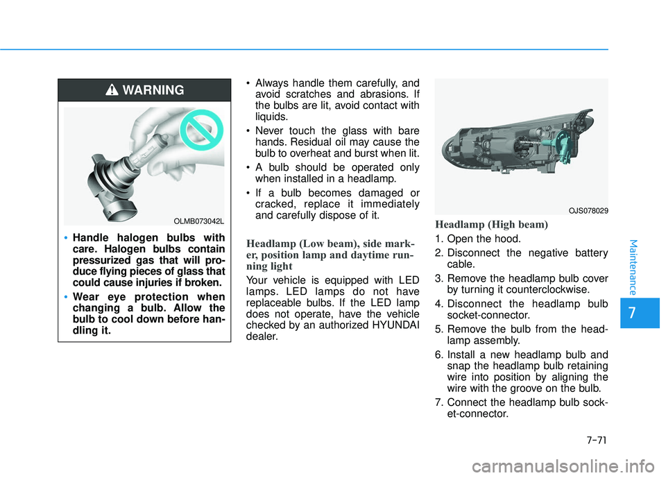
Headlamp (High beam)
1. Open the hood.
2. Disconnect the negative battery cable.
3. Remove the headlamp bulb cover by turning it counterclockwise.
4. Disconnect the headlamp bulb socket-connector.
5. Remove the bulb from the head- lamp assembly.
6. Install a new headlamp bulb and snap the headlamp bulb retaining
wire into position by aligning the
wire with the groove on the bulb.
7. Connect the headlamp bulb sock- et-connector.
OJS078029
Handle halogen bulbs with
care. Halogen bulbs contain
pressurized gas that will pro-
duce flying pieces of glass that
could cause injuries if broken.
Wear eye protection when
changing a bulb. Allow the
bulb to cool down before han-
dling it.
WARNING
OLMB073042L
Page 451 of 491
7-77
7
Maintenance
1. Using a flat-head screwdriver,gently pry the lens from the interi-
or light housing.
2. Remove the bulb by pulling it straight out.
3. Install a new bulb in the socket.
4. Align the lens tabs with the interior light housing notches and snap
the lens into place.
Be careful not to damage the
cover, tab, and plastic housing.
NOTICE
Prior to working on the Interior
Lights, ensure that the "OFF"
button is depressed to avoid
burning your fingers or receiv-
ing an electric shock.
WARNING
Map lamp, room lamp, vanity mirror lamp and luggage compartment lamp
Interior Light Bulb Replacement
OOS077053
■ Map lamp
OOS077054
■Room lamp - without sunroof
OJS078041
■Vanity mirror lamp
OJS078042
■ Luggage compartment lamp