Page 210 of 522
3-125
Convenient features of your vehicle
3
A/C MAX-Level (B, D)
The A/C MAX mode is used to cool
the inside of the vehicle more quick-
ly. Air flow is directed toward the
upper body and face.
In this mode, the air conditioning and
the recirculated air position will be
selected automatically.
After the vehicle interior has cooled
down initially, resume using normal
A/C mode. Continuous use of A/C
MAX mode is not recommended.
Instrument panel vents
The outlet vents can be opened ( )
or closed ( ) separately using the
thumbwheel.
Also, you can adjust the direction of
air delivered from these vents using
the vent control lever as shown.
Temperature control
The temperature will increase by
turning the knob to the right.
The temperature will decrease by
turning the knob to the left.
OLF047208OLF047209OLF047210
Page 221 of 522
3-136
Convenient features of your vehicle
The air flow outlet direction is cycled
as follows:
Face-Level (B, D, F)
Air flow is directed toward the upper
body and face. Additionally, each
outlet can be controlled to direct the
air discharged from the outlet.
Bi-Level (B, C, D, E, F)
Air flow is directed towards the face
and the floor.
Floor & Defrost (A, C, D, E)
Most of the air flow is directed to the
floor and the windshield with a small
amount directed to the side window
defrosters.
Floor-Level (A, C, D, E)
Most of the air flow is directed to the
floor, with a small amount of the air
being directed to the windshield and
side window defrosters.Defrost-Level (A)
Most of the air flow is directed to the
windshield with a small amount of air
directed to the side window
defrosters.
OLF047220
Page 248 of 522

4-5
Multimedia System
How vehicle audio works
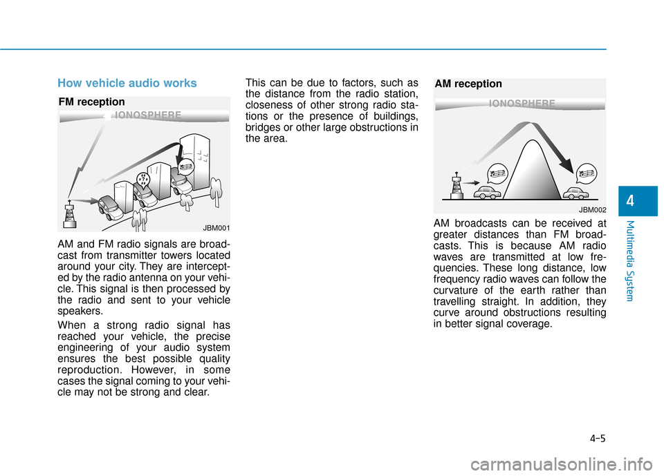
AM and FM radio signals are broad-
cast from transmitter towers located
around your city. They are intercept-
ed by the radio antenna on your vehi-
cle. This signal is then processed by
the radio and sent to your vehicle
speakers.
When a strong radio signal has
reached your vehicle, the precise
engineering of your audio system
ensures the best possible quality
reproduction. However, in some
cases the signal coming to your vehi-
cle may not be strong and clear.This can be due to factors, such as
the distance from the radio station,
closeness of other strong radio sta-
tions or the presence of buildings,
bridges or other large obstructions in
the area.
AM broadcasts can be received at
greater distances than FM broad-
casts. This is because AM radio
waves are transmitted at low fre-
quencies. These long distance, low
frequency radio waves can follow the
curvature of the earth rather than
travelling straight. In addition, they
curve around obstructions resulting
in better signal coverage.
4
JBM001
FM reception
JBM002
AM reception
Page 252 of 522

5
Blind Spot Detection System (BSD) ..................5-89
BSD (Blind Spot Detection) /
LCA (Lane Change Assist) .............................................5-90
RCTA (Rear Cross Traffic Alert) ..................................5-93
Automatic emergency braking (AEB) ...............5-97
System setting and activation......................................5-97
AEB warning message and system control ..............5-99
Sensor to detect the distance from the vehicle
in front (front radar) ...................................................5-102
System malfunction......................................................5-103
Limitation of the system .............................................5-105
Special Driving Conditions ................................5-109
Hazardous Driving Conditions....................................5-109
Rocking the Vehicle ......................................................5-109
Smooth Cornering .........................................................5-110
Driving at Night .............................................................5-110
Driving in the Rain ........................................................5-111
Driving in Flooded Areas.............................................5-111
Winter Driving ....................................................5-112
Snow or Icy Conditions................................................5-112
Winter Precautions .......................................................5-114
Vehicle Load Limit..............................................5-116
Tire Loading Information Label .................................5-117
Trailer Towing .....................................................5-121
Page 257 of 522

5-7
Driving your vehicle
5
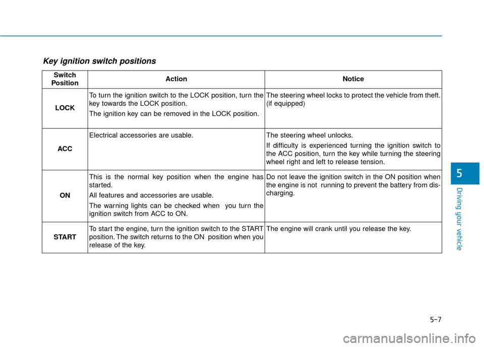
Key ignition switch positions
Switch
PositionActionNotice
LOCK
To turn the ignition switch to the LOCK position, turn the
key towards the LOCK position.
The ignition key can be removed in the LOCK position.The steering wheel locks to protect the vehicle from theft.
(if equipped)
ACC
Electrical accessories are usable.The steering wheel unlocks.
If difficulty is experienced turning the ignition switch to
the ACC position, turn the key while turning the steering
wheel right and left to release tension.
ON
This is the normal key position when the engine has
started.
All features and accessories are usable.
The warning lights can be checked when you turn the
ignition switch from ACC to ON.Do not leave the ignition switch in the ON position when
the engine is not running to prevent the battery from dis-
charging.
START
To start the engine, turn the ignition switch to the START
position. The switch returns to the ON position when you
release of the key.The engine will crank until you release the key.
Page 258 of 522

5-8
Starting the engine
1. Make sure the parking brake isapplied.
2. Make sure the shift lever is in P (Park).
3. Depress the brake pedal.
4. Turn the ignition switch to the START position. Hold the key
(maximum of 10 seconds) until the
engine starts and release it.
Information
• Do not wait for the engine to warmup while the vehicle remains station-
ary. Start driving at moderate
engine speeds. (Steep accelerating
and decelerating should be avoided.)
• Whether the engine is cold or warm, always start the vehicle with your
foot on the brake pedal. Do not
depress the accelerator while start-
ing the vehicle. Do not race the
engine while warming it up. To prevent damage to the vehicle:
Do not hold the ignition key in
the START position for more
than 10 seconds. Wait 5 to 10
seconds before trying again.
If traffic and road conditions permit, you may put the shift
lever in the N (Neutral) position
while the vehicle is still moving
and turn the ignition switch to
the START position in an
attempt to restart the engine.
Do not push or tow your vehicle to start the engine.
NOTICEi
Driving your vehicle
Always wear appropriate shoes
when operating your vehicle.
Unsuitable shoes, such as high
heels, ski boots, sandals, flip-
flops, etc., may interfere with
your ability to use the brake and
accelerator pedals.
WARNING
Page 263 of 522

5-13
Driving your vehicle
5
To prevent damage to the vehicle:
If the engine stalls while you arein motion, do not attempt to
move the shift lever to the P
(Park) position.
If traffic and road conditions
permit, you may put the shift
lever in the N (Neutral) position
while the vehicle is still moving
and press the Engine Start/Stop
button in an attempt to restart
the engine.
Do not push or tow your vehicle to start the engine. To prevent damage to the vehicle:
When the stop lamp fuse is blown,
you can't start the engine normal-
ly. Replace the fuse with a new
one. If you are not able to replace
the fuse, you can start the engine
by pressing and holding the
Engine Start/Stop button for 10 sec-
onds with the Engine Start/Stop
button in the ACC position.
Do not press the Engine Start/Stop
button for more than 10 seconds
except when the stop
lamp fuse is
blown.
For your safety always depress
the brake pedal before starting the
engine.
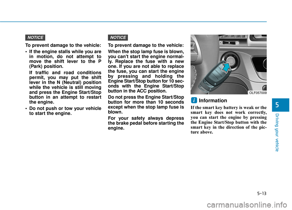
Information
If the smart key battery is weak or the
smart key does not work correctly,
you can start the engine by pressing
the Engine Start/Stop button with the
smart key in the direction of the pic-
ture above.
i
NOTICENOTICE
OLF057009
Page 283 of 522
5-33
Driving your vehicle
5
If the Parking Brake WarningLight is still on even though the
EPB has been released, have
your vehicle checked by an
authorized HYUNDAI dealer.
Do not drive your vehicle with the EPB applied. It may cause
excessive brake pad and brake
rotor wear.
When the EPB (Electronic Parking
Brake) does not release:
Contact an authorized HYUNDAI
dealer by loading the vehicle on a
flatbed tow truck and have the sys-
tem checked.
EPB (Electronic Parking Brake)
may be automatically applied
when:
The EPB is overheated
Requested by other systems
The engine is turned off with theEPB applied
Information
If the driver turns the engine off while
Auto Hold is operating, EPB will be
automatically applied. However, if
you press the EPB switch within one
second after the engine is turned off,
the EPB will not be applied.
iNOTICE
OLF057587L