Page 95 of 570
Safety features of your vehicle
74
3
Why didn’t my air bag go off in a
collision? (Inflation and non-infla-
tion conditions of the air bag)
There are many types of accidents
in which the air bag would not be
expected to provide additional
protection.
These include rear impacts, sec-
ond or third collisions in multiple
impact accidents, as well as low
speed impacts.Air bag collision sensors
(1) SRS control module /
Rollover sensor
(2) Front impact sensor (3)
Pressure type side impact sensor
(4) Acceleration type side impact
sensor
ONC036001/ONC037006N/ONC036002/OANNSA2038/ODM032048
1234
Page 96 of 570
375
Safety features of your vehicle
Problems may arise if the sensorinstallation angles are changed
due to the deformation of the front
bumper, body or C pillars or front
door where side collision sensors
are installed. Have the vehicle
checked and repaired by an
authorized HYUNDAI dealer.
Your vehicle has been designed to absorb impact and deploy the air
bag(s) in certain collisions. Installing
bumper guards or side steppers or
replacing a bumper with non-gen-
uine parts may adversely affect your
vehicle’s collision and air bag
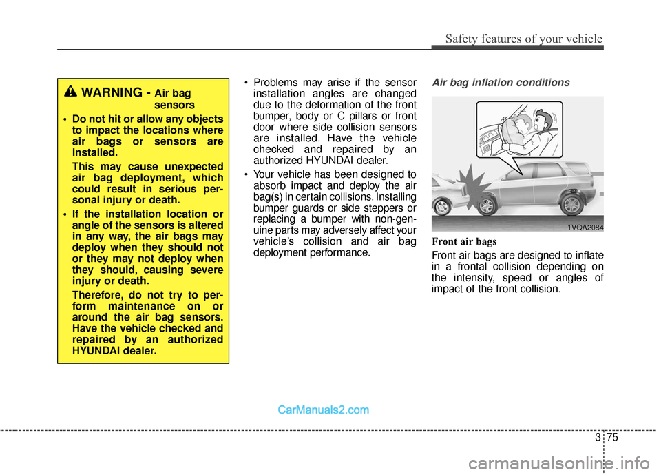
deployment performance.Air bag inflation conditions
Front air bags
Front air bags are designed to inflate
in a frontal collision depending on
the intensity, speed or angles of
impact of the front collision.
WARNING - Air bag
sensors
Do not hit or allow any objects to impact the locations where
air bags or sensors are
installed.
This may cause unexpected
air bag deployment, which
could result in serious per-
sonal injury or death.
If the installation location or angle of the sensors is altered
in any way, the air bags may
deploy when they should not
or they may not deploy when
they should, causing severe
injury or death.
Therefore, do not try to per-
form maintenance on or
around the air bag sensors.
Have the vehicle checked and
repaired by an authorized
HYUNDAI dealer.
1VQA2084
Page 98 of 570
377
Safety features of your vehicle
Air bag non-inflation conditions
In certain low-speed collisions theair bags may not deploy. The air
bags are designed not to deploy in
such cases because they may not
provide benefits beyond the pro-
tection of the seat belts in such col-
lisions. Air bags are not designed to inflate
in rear collisions, because occu-
pants are moved backward by the
force of the impact. In this case,
inflated air bags would not be able
to provide any additional benefit. Front air bags may not inflate in
side impact collisions, because
occupants move to the direction of
the collision, and thus in side
impacts, frontal air bag deployment
would not provide additional occu-
pant protection.
However, side and curtain air bags
may inflate depending on the inten-
sity, vehicle speed and angles of
impact.
OVQ036018NOUN036087
1VQA2086
Page 135 of 570
Features of your vehicle
32
4
✽
✽
NOTICE
• The power liftgate (power tailgate)
can be operated when the engine is
not running. However the power
liftgate (power tailgate) operation
consumes large amounts of vehicle
electric power. To prevent the bat-
tery from being discharged, do not
operate it excessively.
• To prevent the battery from being discharged, do not leave the power
liftgate (power tailgate) in the
open position for a long time.
• Do not modify or repair any part of the power liftgate (power tail-
gate) by yourself. This must be
done by an authorized HYUNDAI
dealer.
• When jacking up the vehicle to change a tire or repair the vehicle,
do not operate the power liftgate
(power tailgate). This could cause
the power liftgate (power tailgate)
to operate improperly.
• In cold and wet climates, the power liftgate (power tailgate) may
not work properly due to freezing
conditions.
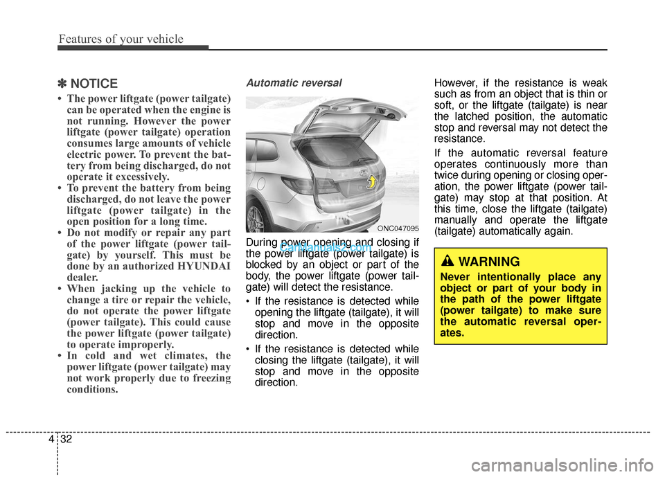
Automatic reversal
During power opening and closing if
the power liftgate (power tailgate) is
blocked by an object or part of the
body, the power liftgate (power tail-
gate) will detect the resistance.
If the resistance is detected while
opening the liftgate (tailgate), it will
stop and move in the opposite
direction.
If the resistance is detected while closing the liftgate (tailgate), it will
stop and move in the opposite
direction. However, if the resistance is weak
such as from an object that is thin or
soft, or the liftgate (tailgate) is near
the latched position, the automatic
stop and reversal may not detect the
resistance.
If the automatic reversal feature
operates continuously more than
twice during opening or closing oper-
ation, the power liftgate (power tail-
gate) may stop at that position. At
this time, close the liftgate (tailgate)
manually and operate the liftgate
(tailgate) automatically again.
WARNING
Never intentionally place any
object or part of your body in
the path of the power liftgate
(power tailgate) to make sure
the automatic reversal oper-
ates.
ONC047095
Page 166 of 570
463
Features of your vehicle
To adjust the Zone setting:
1. Determine the desired ZoneNumber based upon your current
location on the Zone Map.
2. Press and hold the button for 6 seconds, the current Zone
Number will appear on the display.
3. Pressing and holding the button again will cause the numbers to
increment (Note: they will repeat
…13, 14, 15, 1, 2, …). Releasing
the button when the desired Zone
Number appears on the display
will set the new Zone.
4. Within about 5 seconds the com- pass will start displaying a com-
pass heading again.
There are some conditions that can
cause changes to the vehicle mag-
nets, such as installing a ski rack or
a CB antenna. Body repair work on
the vehicle can also cause changes
to the vehicle's magnetic field. In
these situations, the compass will
need to be re-calibrated to quickly
correct for these changes. To re-cali-
brate the compass: 1. Press and hold the button for
more than 9 seconds. When the
compass memory is cleared a "C"
will appear in the display.
2. To calibrate the compass, drive the vehicle in 2 complete circles at
less than 5 mph (8 km/h). Integrated HomeLink®Wireless
Control System
The HomeLink
®Wireless Control
System provides a convenient way to
replace up to three hand-held radio-
frequency (RF) transmitters with a
single built-in device. This innovative
feature will learn the radio frequency
codes of most current transmitters to
operate devices such as gate opera-
tors, garage door openers, entry
door locks, security systems, even
home lighting. Both standard and
rolling code-equipped transmitters
can be programmed by following the
outlined procedures. Additional
HomeLink
®information can be found
at: www.homelink.com or by calling
1-800-355-3515.
Page 217 of 570
Features of your vehicle
114
4
If you desire to deactivate the rear
parking assist system, press the
rear parking assist OFF button
again. (The indicator on the button
will illuminate.) To turn the system
on, press the button again. (The
indicator on the button will go off.)
This system will activate when backing up with the ignition switch
ON.
If the vehicle is moving at a speed
over 6 mph (10 km/h), the system
will be deactivated.
The sensing distance while the rear parking assist system is in
operation is approximately 47 in.
(120 cm).
When more than two objects are sensed at the same time, the clos-
est object will be recognized first. Types of warning sound
When an object is 47 in. to 24 in.
(120 cm to 61 cm) from the rear
bumper: Buzzer beeps intermit-
tently.
When an object is 23 in. to 12 in. (60 cm to 31 cm) from the rear
bumper: Buzzer beeps more fre-
quently.
When an object is within 11.8 in. (30 cm) of the rear bumper:
Buzzer sounds continuously.Non-operational conditions of
rear parking assist system
The rear parking assist system may
not operate properly when:
1. Moisture is frozen to the sensor. (It will operate normally when the
moisture has been cleared.)
2. The sensor is covered with foreign matter, such as snow or water, or
the sensor cover is blocked. (It will
operate normally when the materi-
al is removed or the sensor is no
longer blocked.)
3. Driving on uneven road surfaces (unpaved roads, gravel, bumps,
gradient).
4. Objects generating excessive noise (vehicle horns, loud motor-
cycle engines, or truck air brakes)
are within range of the sensor.
5. Heavy rain or water spray exists.
6. Wireless transmitters or mobile phones are within range of the
sensor.
7. Trailer towing.
Page 242 of 570
4139
Features of your vehicle
MANUAL CLIMATE CONTROL SYSTEM (IF EQUIPPED)
ONCNCL2001/ODM042273/ONCNCL2002
1. Front windshield defrost button
2. Temperature control button
3. Air conditioning button
4. MAX A/C (Max airconditioning) button
5. Rear window defroster button
6. Air intake control button
7. Mode selection button
8. Fan speed control knob
9. 3
rdrow climate control ON/OFF
button
10. 3
rdrow fan speed control knob
11. 3
rdrow blower ON/OFF button
12. 3
rdrow mode selection button
13. 3
rdrow temperature control knob
* if equipped
■
■ Front climate control (Type A) ■
■
Front climate control (Type B)
■
■3rdrow air climate control (for Type A)
Page 243 of 570
Features of your vehicle
140
4
Heating and air conditioning
1. Start the engine.
2. Set the mode to the desired posi-
tion.
For improving the effectiveness of
heating and cooling;- Heating:
- Cooling:
3. Set the temperature control to the desired position.
4. Set the air intake control to the outside (fresh) air position. (if
equipped)
5. Set the fan speed control to the desired speed.
6. If air conditioning is desired, turn the air conditioning system (if
equipped) on.
ONC047083
❈
❈
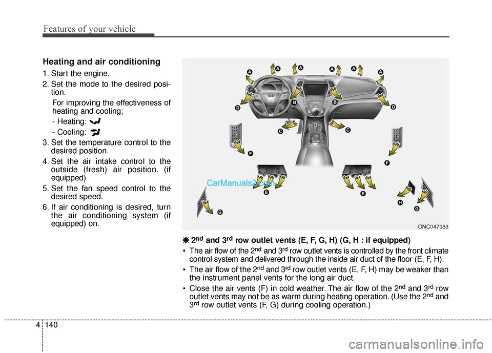
2ndand 3rdrow outlet vents (E, F, G, H) (G, H : if equipped)
• The air flow of the 2
ndand 3rdrow outlet vents is controlled by the front climate
control system and delivered through the inside air duct of the floor (E, F, H).
The air flow of the 2
ndand 3rdrow outlet vents (E, F, H) may be weaker than
the instrument panel vents for the long air duct.
Close the air vents (F) in cold weather. The air flow of the 2
ndand 3rdrow
outlet vents may not be as warm during heating operation. (Use the 2ndand
3rdrow outlet vents (F, G) during cooling operation.)