Page 559 of 599
7-51
7
Maintenance
TypeSymbolFuse RatingCircuit Protected
Multi Fuse
PTC
HEATER250AEngine Room Junction Block
CLUTCH
ACTUATOR40AClutch Actuator
Fuse
DCT315ATCM
HPCU110AHPCU
EWP10AElectric Water Pump (HEV)
140AIGPM
DCT240ATCM
DCT140ATCM
10AEngine Room Junction Block
1 ACTIVE
HYDRAULIC BOSSTER40AMultipurpose Check Connector, IBAU
2 ACTIVE
HYDRAULIC BOSSTER30AMultipurpose Check Connector, IBAU
POWER
OUTLET140AEngine Room Junction Block
B/UP
LAMP10AAudio, Rear Combination Lamp (IN) LH/RH, Electro Chromic Mirror
Engine compartment fuse panel
Page 560 of 599
7-52
Maintenance
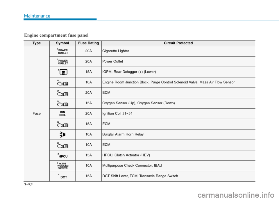
TypeSymbolFuse RatingCircuit Protected
Fuse
POWER
OUTLET320ACigarette Lighter
POWER
OUTLET220APower Outlet
215AIGPM, Rear Defogger (+) (Lower)
S210AEngine Room Junction Block, Purge Control Solenoid Valve, Mass Air Flow Sensor
E120AECM
S115AOxygen Sensor (Up), Oxygen Sensor (Down)
IGN
COIL20AIgnition Coil #1~#4
E215AECM
10ABurglar Alarm Horn Relay
E310AECM
HPCU215AHPCU, Clutch Actuator (HEV)
3 ACTIVE
HYDRAULIC BOSSTER10AMultipurpose Check Connector, IBAU
DCT415ADCT Shift Lever, TCM, Transaxle Range Switch
Engine compartment fuse panel
Page 571 of 599
7-63
7
Maintenance
Type B
If the LED lamp does not operate, we
recommended that you have the
vehicle checked by a HYUNDAI
authorised repairer.
Rear combination lamp bulb
replacement
Type A
(1) Tail/Stop lamp
(2) Turn signal lamp
(3) Tail lamp
(4) Backup lamp
Tail/Stop lamp and turn signal lamp
1. Turn off the engine.
2. Open the tailgate.
3. Open the lamp assembly retainingscrew covers.
4. Loosen the lamp assembly retain- ing screws with a cross-tip screw-
driver.OAE076034
OAE076035
OAE076037
Page 573 of 599
7-65
7
Maintenance
Tail lamp and backup lamp
1. Turn off the engine.
2. Open the tailgate.
3. Remove the service cover using aflat-blade screwdriver. 4. Remove the bulb by pulling it
straight out.
5. Insert a new bulb by inserting it into the socket and rotating it until
it locks into place.
6. Install the socket into the assembly by aligning the tabs on the socket
with the slots in the assembly.
Push the socket into the assembly
and turn the socket clockwise.
7. Reinstall the service cover.
Type B
(1) Tail/Stop lamp
(2) Turn signal lamp
(3) Tail lamp
(4) Backup lamp
Tail/Stop lamp
If the LED lamp does not operate, we
recommended that you have the
vehicle checked by a HYUNDAI
authorised repairer.
OAE076036
OAE076041OAE076042
Backup lamp
Page 586 of 599

7-78
Maintenance
1. Crankcase emission controlsystem
The positive crankcase ventilation
system is employed to prevent air
pollution caused by blow-by gases
being emitted from the crankcase.
This system supplies fresh filtered air
to the crankcase through the air
intake hose. Inside the crankcase,
the fresh air mixes with blow-by
gases, which then pass through the
PCV valve into the induction system.
2. Evaporative emission controlsystem
The Evaporative Emission Control
System is designed to prevent fuel
vapours from escaping into the
atmosphere.
Canister
Fuel vapours generated inside the
fuel tank are absorbed and stored in
the onboard canister. When the
engine is running, the fuel vapours
absorbed in the canister are drawn
into the surge tank through the purge
control solenoid valve.
Purge Control Solenoid Valve
(PCSV)
The purge control solenoid valve is
controlled by the Engine Control
Module (ECM); when the engine
coolant temperature is low during
idling, the PCSV closes so that evap-
orated fuel is not taken into the
engine. After the engine warms-up
during ordinary driving, the PCSV
opens to introduce evaporated fuel to
the engine.
3. Exhaust emission control system
The Exhaust Emission Control
System is a highly effective system
which controls exhaust emissions
whilst maintaining good vehicle per-
formance.
When the engine starts or fails to
start, excessive attempts to restart
the engine may cause damage to the
emission system.
Engine exhaust
(carbon monoxide) precautions
Carbon monoxide can be present
with other exhaust fumes. If you
smell exhaust fumes of any kind in
your vehicle, drive with all the win-
dows fully open. Have your vehicle
checked and repaired immediately.
Engine exhaust gases contain
carbon monoxide (CO). Though
colourless and odourless, it is
dangerous and could be lethal if
inhaled. Follow the instructions
on this page to avoid CO poi-
soning.
WARNING
Page 588 of 599

Do not modify or tamper with anypart of the engine or emission con-
trol system. All inspections and
adjustments must be made by a
HYUNDAI authorised repairer.
Avoid driving with an extremely low fuel level.
Running out of fuel could cause
the engine to misfire, damaging
the catalytic converter.
Gasoline (Petrol) ParticulateFilter (GPF) (if equipped)
The Gasoline (Petrol) Particulate
Filter (GPF) system removes the
soot in the exhaust gas.
The GPF system automatically burns
(or oxidises) the accumulated soot in
accordance with driving situations,
unlike a disposable air filter.
In other words, the accumulated soot
is automatically purged out by the
engine control system and by the
high exhaust-gas temperature at nor-
mal/ high driving speeds. However, when the vehicle is contin-
ually driven at repeated short dis-
tances or driven at low speed for a
long time, the accumulated soot may
not be automatically removed
because of low exhaust gas temper-
ature. In this case, the accumulated
soot is out of the detection range, the
soot oxidization process does not
occur, and the Gasoline (Petrol)
Particulate Filter (GPF) Lamp ( )
Illuminates.
The Gasoline (Petrol) Particulate
Filter (GPF) Lamp stops illuminating,
when the driving speed exceeds 50
mph (80km/h) with engine rpm 1,500
~ 4,000 and the gear in the 3rd posi-
tion or above for approximately 30
minutes.
When the GPF Lamp continuously
blinks or the warning message
“Check exhaust system” illuminates in
the above cases, we recommend that
you have the GPF system checked by
a HYUNDAI authorised repairer.
When the vehicle is continuously
driven with the GPF Lamp flashing
for an extended period of time, it may
damage the GPF system and lower
the fuel economy.
Lean NOx Trap (if equipped)
The Lean NOx Trap (LNT) system
removes the nitrogen oxide from the
exhaust gas. A smell can occur in the
exhaust gas depending on the quali-
ty of the fuel, and it can degrade NOx
reduction performance. Please use
the regulated automotive diesel fuel.
Maintenance
7-80
Gasoline (Petrol) Fuel
(if equipped with GPF)
We recommend you to use only
the regulated petrol fuels, when
your vehicle is equipped with
the GPF system.
When you use other petrol fuels
which contain unspecified addi-
tives, they may damage the GPF
system and cause exhaust
emission problems.
CAUTION
Page 589 of 599

P
PR
R O
O C
CE
E D
D U
U R
RE
E
F
F O
O R
R
E
E N
N T
TE
ER
R I
IN
N G
G
F
F O
O R
RC
CE
E D
D
E
E N
N G
GI
IN
N E
E
A
A C
CT
T I
IV
V A
A T
TI
IO
O N
N
M
M O
OD
DE
E
If the engine needs to be kept run-
ning whilst the vehicle is stopped to
inspect emission gas or perform
vehicle maintenance, follow below
procedure to enter forced engine
activation mode.
1. Place the shift lever in P (Park)
position with the vehicle stopped.
Engage the parking brake. Then,
follow the steps (1) to (5).
Information
Below steps from (1) to (5) must be
completed within 60 sec. If not, the
process is reset and you must start
again from step (1). (1) Turn the ignition switch to the ON
position. Vehicles equipped with
the smart key, press the Engine
Start/Stop button twice without
depressing the brake pedal.
(2) Place the shift lever in P (Park) position and depress the acceler-
ator pedal twice.
(3) Place the shift lever in N (Neutral) position and depress the acceler-
ator pedal twice.
(4) Place the shift lever in P (Park) position and depress the acceler-
ator pedal twice.
(5) With the brake pedal depressed, start the engine, and maintain
idling state.
Information
The engine remains in idle state and
the forced engine activation mode is
maintained even when the gear is
shifted to a different position. 2. " " indicator on the instrument
cluster blinks when the vehicle is
in forced engine activation mode.
Check the " " indicator blinking
to ensure that the forced engine
activation mode is correctly
entered.
Information
The " " indicator continues blink-
ing until the forced engine activation
mode is cancelled. When the mode is
cancelled the " " indicator will
stop blinking.
3. To cancel the forced engine acti-vation mode, turn the vehicle off.
i
i
i
7-81
7
Maintenance
Page 596 of 599

8-7
8
Specifications & Consumer information
Always be sure to clean the area
around any filler plug, drain
plug, or dipstick before check-
ing or draining any lubricant.
This is especially important in
dusty or sandy areas and when
the vehicle is used on unpaved
roads. Cleaning the plug and
dipstick areas will prevent dirt
and grit from entering the
engine and other mechanisms
that could be damaged.
CAUTION
Engine oil viscosity (thickness) has an effect on fuel economy and cold
weather operating (engine start and engine oil flowability). Lower viscosity
engine oils can provide better fuel economy and cold weather performance,
however, higher viscosity engine oils are required for satisfactory lubrication
in hot weather. Using oils of any viscosity other than those recommended
could result in engine damage.
When choosing an oil, consider the range of temperature your vehicle will be
operated in before the next oil change. Proceed to select the recommended
oil viscosity from the chart.
Temperature Range for SAE Viscosity Numbers
Temperature
Petrol Engine Oil
°C
(°F)-30 -20 -10 0 10 20 30 40 50 -10 0 20 40 60 80 100 120
20W-50
15W-40
10W-30
0/5W-30, 5W-40
Recommended SAE viscosity
number Recommended engine oil (For Europe)
Supplier Product
Petrol Engine
Shell Helix Ultra AH 5W-30
Helix Ultra A5/B5 0W-30