Page 486 of 603
7-41
7
Maintenance
Wheel size designation
Wheels are also marked with impor-
tant information that you need if you
ever have to replace one. The follow-
ing explains what the letters and
numbers in the wheel size designa-
tion mean.
Example wheel size designation:
6.5J X 15
6.5 - Rim width in inches.
J - Rim contour designation.
15 - Rim diameter in inches.
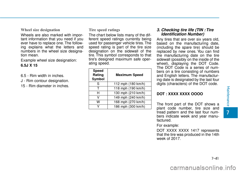
Tire speed ratings
The chart below lists many of the dif-
ferent speed ratings currently being
used for passenger vehicle tires. The
speed rating is part of the tire size
designation on the sidewall of the
tire. This symbol corresponds to that
tire's designed maximum safe oper-
ating speed.
3. Checking tire life (TIN : TireIdentification Number)
Any tires that are over six years old,
based on the manufacturing date,
(including the spare tire) should be
replaced by new ones. You can find
the manufacturing date on the tire
sidewall (possibly on the inside of the
wheel), displaying the DOT Code.
The DOT Code is a series of num-
bers on a tire consisting of numbers
and English letters. The manufactur-
ing date is designated by the last four
digits (characters) of the DOT code.
DOT : XXXX XXXX OOOO
The front part of the DOT shows a
plant code number, tire size and
tread pattern and the last four num-
bers indicate week and year manu-
factured.
For example:
DOT XXXX XXXX 1417 represents
that the tire was produced in the 14th
week of 2017.
Speed
Rating
Symbol Maximum Speed
S 112 mph (180 km/h) T 118 mph (190 km/h)
H 130 mph (210 km/h) V 149 mph (240 km/h)
W 168 mph (270 km/h) Y 186 mph (300 km/h)
Page 536 of 603
H
Hy
yb
br
ri
id
d
S
S y
ys
st
te
e m
m
O
O v
ve
e r
rv
v i
ie
e w
w
HEV (Hybrid Electric Vehicle) System..................H2
Hybrid Vehicle ......................................................................H2\
PHEV (Plug-in Electric Vehicle) System ..............H3
Plug-in Hybrid Vehicle.......................................................H3
Charging the Plug-in Hybrid Vehicle....................H4
Charging Information .........................................................H4
Charging Types ....................................................................H4
Charging Time Information ...............................................H4
Charging Status ...................................................................H5
Charging Connector AUTO/LOCK Mode .......................H6
Scheduled Charging ............................................................H7
Charging Precautions .........................................................H8
Normal Charge .....................................................................H9
Trickle Charge ....................................................................H15
Driving the Hybrid/Plug-in Hybrid Vehicle .......H27
Starting the Vehicle ..........................................................H27
Special Features ................................................................H28
Hybrid System Gauge ......................................................H30
Plug-in Hybrid Mode (Plug-in hybrid vehicle)..........H31
Aux. Battery Saver+ (Plug-in hybrid vehicle) ...........H32
Warning and Indicator Lights ........................................H34
LCD Display Messages.....................................................H35
Energy flow ........................................................................\
H43
Safety Precautions for Hybrid System ..............H47
High Voltage Battery System.........................................H47
Safety Plug ........................................................................\
.H50
High Voltage Battery Cooling Duct ..............................H50
If an Accident Occurs ......................................................H52
When the Hybrid Vehicle Shuts Off ............................H53
Page 547 of 603
H12
Information
• Even though charging is possiblewith the Engine Start/Stop button in
the ON/START position, for your
safety, start charging when the
Engine Start/Stop button is in the
OFF position and the vehicle shifted
to P (Park). After charging has
started, you can use electrical com-
ponents such as the radio by press-
ing the Engine Start/Stop button to
the ACC or ON position.
• During normal charging, the radio reception may be bad.
• Moving the shift lever from P (Park) to R (Reverse)/N (Neutral)/D
(Drive) stops the charging process.
To restart the charging process,
move the shift lever to P (Park),
place the Engine Start/Stop button
to the OFF position, and disconnect
the charging cable. Then, connect
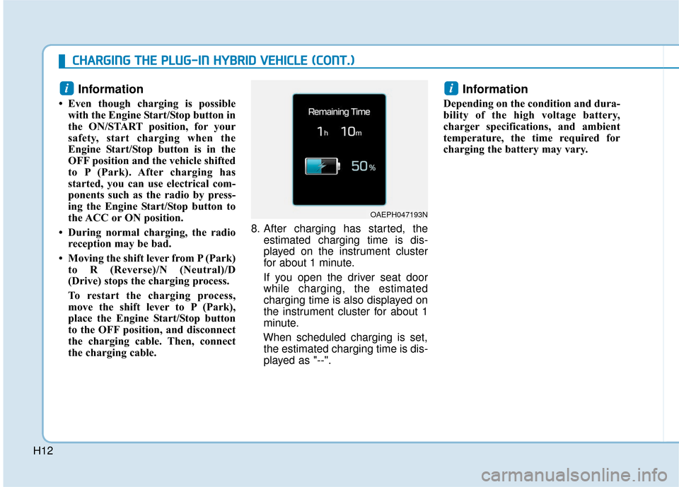
the charging cable. 8. After charging has started, the
estimated charging time is dis-
played on the instrument cluster
for about 1 minute.
If you open the driver seat door
while charging, the estimated
charging time is also displayed on
the instrument cluster for about 1
minute.
When scheduled charging is set, the estimated charging time is dis-
played as "--".
Information
Depending on the condition and dura-
bility of the high voltage battery,
charger specifications, and ambient
temperature, the time required for
charging the battery may vary.
ii
OAEPH047193N
C
C H
H A
AR
RG
G I
IN
N G
G
T
T H
H E
E
P
P L
LU
U G
G-
-I
IN
N
H
H Y
Y B
BR
RI
ID
D
V
V E
EH
H I
IC
C L
LE
E
(
( C
C O
O N
NT
T.
.)
)
Page 551 of 603
H16
How to set the charge level ofthe portable charger
1. Check the rated current of the
electric outlet prior to connecting
the plug to the outlet.
2. Connect the plug to a household electric outlet.
3. Check the display window on the control box. 4. Press the button (1) on the back of
the control box for more than 1
second to adjust the charge level.
(Refer to charging cable type and
example for setting the charge
level.)
5. The display window on the control box changes from H and M to L
every time you press the button
(1). 6. When setting the charge level is
complete, start charging accord-
ing to the trickle charge proce-
dure.
OAEEQ018083
C
CH
H A
AR
RG
G I
IN
N G
G
T
T H
H E
E
P
P L
LU
U G
G-
-I
IN
N
H
H Y
Y B
BR
RI
ID
D
V
V E
EH
H I
IC
C L
LE
E
(
( C
C O
O N
NT
T.
.)
)
OAEE046506N
PlugElectric Outlet
Page 552 of 603
H17
How to Connect PortableCharger (ICCB: In-Cable ControlBox)
1. Connect the plug to a household
electric outlet.
❈Example for setting the ICCB charge level
(The example is only for reference and may vary according to the sur-
rounding environment.)
Outlet currentICCB charge levelControl box display window
14-16A12A
13-12A10A
11-10A8A
9-8A6A
OAEE046506N
PlugElectric Outlet
Page 555 of 603
H20
C
CH
H A
AR
RG
G I
IN
N G
G
T
T H
H E
E
P
P L
LU
U G
G-
-I
IN
N
H
H Y
Y B
BR
RI
ID
D
V
V E
EH
H I
IC
C L
LE
E
(
( C
C O
O N
NT
T.
.)
)
Information
• Even though charging is possible with the Engine Start/Stop button in
the ON/START position, for your
safety, start charging when the
Engine Start/Stop button is in the
OFF position and the vehicle shifted
to P (Park).
After charging has started, you can
use electrical components such as
the radio by pressing the Engine
Start/Stop button to ACC or ON
position.
• Moving the shift lever from P (Park) to R (Reverse)/N (Neutral)/D
(Drive) stops the charging process.
To restart the charging process,
move the shift lever to P (Park),
place the Engine Start/Stop button
to the OFF position, and disconnect
the charging cable. Then, connect
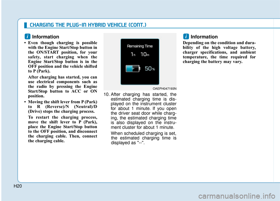
the charging cable. 10. After charging has started, the
estimated charging time is dis-
played on the instrument cluster
for about 1 minute. If you open
the driver seat door while charg-
ing, the estimated charging time
is also displayed on the instru-
ment cluster for about 1 minute.
When scheduled charging is set, the estimated charging time is
displayed as "--".
Information
Depending on the condition and dura-
bility of the high voltage battery,
charger specifications, and ambient
temperature, the time required for
charging the battery may vary.
ii
OAEPH047193N
Page 566 of 603
![Hyundai Ioniq Hybrid 2019 Owners Manual H31
Plug-in Hybrid Mode
(Plug-in hybrid vehicle)
EV/HEV Button
Pressing the [EV/HEV] button
changes the plug-in hybrid system
modes, between Electric (CD) mode
and Hybrid (CS) mode.
Each time the mod Hyundai Ioniq Hybrid 2019 Owners Manual H31
Plug-in Hybrid Mode
(Plug-in hybrid vehicle)
EV/HEV Button
Pressing the [EV/HEV] button
changes the plug-in hybrid system
modes, between Electric (CD) mode
and Hybrid (CS) mode.
Each time the mod](/manual-img/35/14928/w960_14928-565.png)
H31
Plug-in Hybrid Mode
(Plug-in hybrid vehicle)
EV/HEV Button
Pressing the [EV/HEV] button
changes the plug-in hybrid system
modes, between Electric (CD) mode
and Hybrid (CS) mode.
Each time the mode is changed a
corresponding indicator is displayed
on the instrument cluster as follows.
Plug-in Hybrid Mode Indicator
: The high-voltage(hybrid) battery is
used to drive the
vehicle.
:The high-voltage
(hybrid) battery and
gasoline engine is
used to drive the
vehicle.
Information
Even when the battery charging rate
is high and driving in electric mode is
possible, engine may turn on in some
areas to protect the system.
AVN Screen (Plug-in hybrid vehicle) (if equipped)
Press [PHEV] on the [Home] screen
or the [All menus] screen and the
menus related to plug-in hybrid
([ECO Driving], [Energy Information],
[EV Range], [Charging Settings],
[Charging Stations], [Gas Stations])
are displayed.
For more information, please refer
to the Multimedia System Manual
that was separately supplied with
your vehicle.
i
OAEPH047518N
OAEPH047519N
OAEPH047520N
OAEPHQ017003L
Page 568 of 603
H33
System Setting
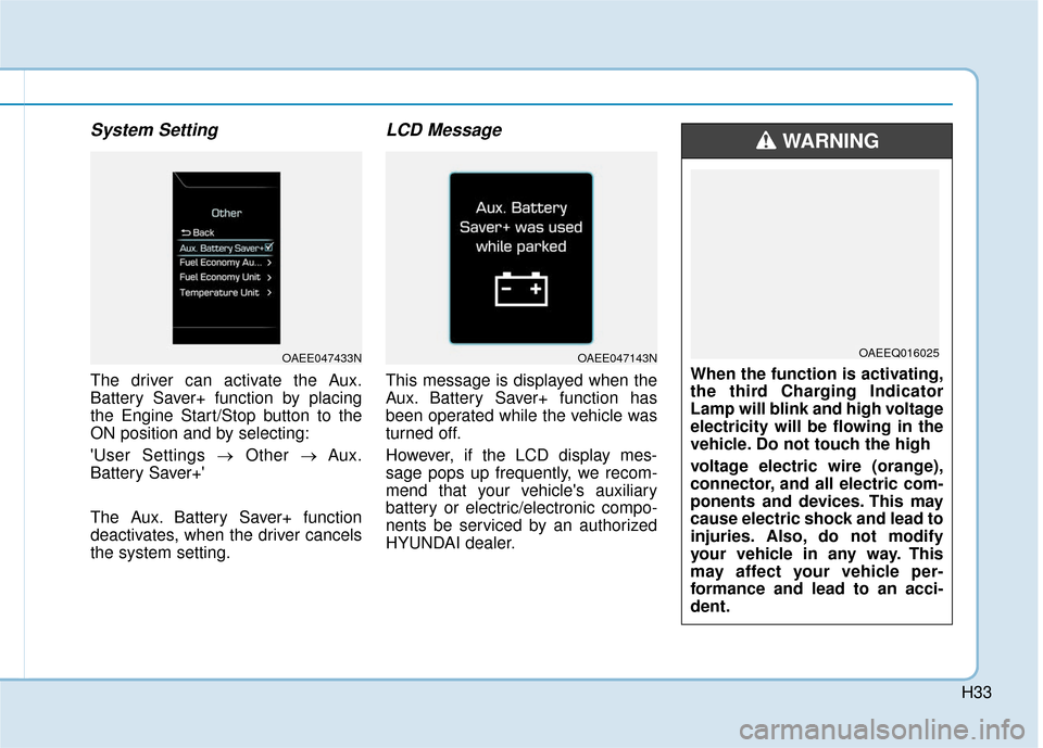
The driver can activate the Aux.
Battery Saver+ function by placing
the Engine Start/Stop button to the
ON position and by selecting:
'User Settings →Other → Aux.
Battery Saver+'
The Aux. Battery Saver+ function
deactivates, when the driver cancels
the system setting.
LCD Message
This message is displayed when the
Aux. Battery Saver+ function has
been operated while the vehicle was
turned off.
However, if the LCD display mes-
sage pops up frequently, we recom-
mend that your vehicle's auxiliary
battery or electric/electronic compo-
nents be serviced by an authorized
HYUNDAI dealer.
OAEE047143N
When the function is activating,
the third Charging Indicator
Lamp will blink and high voltage
electricity will be flowing in the
vehicle. Do not touch the high
voltage electric wire (orange),
connector, and all electric com-
ponents and devices. This may
cause electric shock and lead to
injuries. Also, do not modify
your vehicle in any way. This
may affect your vehicle per-
formance and lead to an acci-
dent.
WARNING
OAEEQ016025OAEE047433N