Page 17 of 551

15
Quick Reference Guide
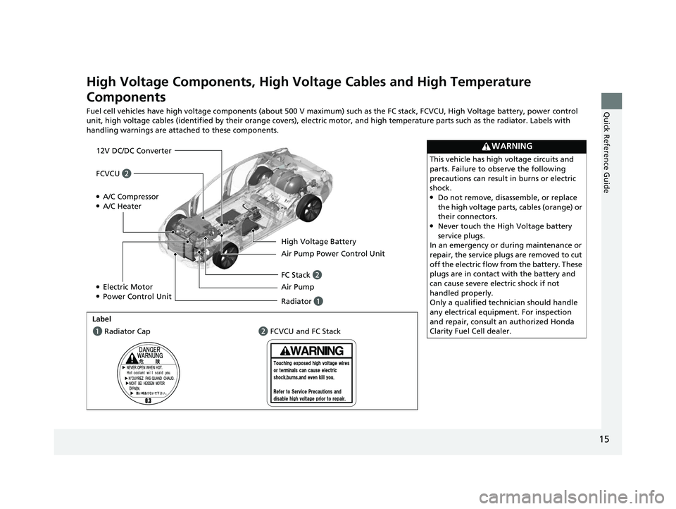
High Voltage Components, High Voltage Cables and High Temperature
Components
Fuel cell vehicles have high voltage components (about 500 V maximum) such as the FC stack, FCVCU, High Voltage battery, power control
unit, high voltage cables (identified by their orange covers), el ectric motor, and high temperature parts such as the radiator. Labels with
handling warnings are attached to these components.
WARNING
This vehicle has high voltage circuits and
parts. Failure to observe the following
precautions can result in burns or electric
shock.
●Do not remove, disassemble, or replace
the high voltage parts, cables (orange) or
their connectors.
●Never touch the High Voltage battery
service plugs.
In an emergency or during maintenance or
repair, the service plugs are removed to cut
off the electric flow from the battery. These
plugs are in contact with the battery and
can cause severe electric shock if not
handled properly.
Only a qualified technician should handle
any electrical equipment. For inspection
and repair, consult an authorized Honda
Clarity Fuel Cell dealer.
12V DC/DC Converter
●A/C Compressor●A/C Heater
Radiator a Air Pump FC Stack b Air Pump Power Control Unit High Voltage Battery
●Electric Motor●Power Control Unit
Labela Radiator Cap b FCVCU and FC Stack
FCVCU b
19 CLARITY FCV CSS-31TRT6200.book 15 ページ 2019年1月17日 木曜日 午前11時 54分
Page 432 of 551

430
uuBraking uAnti-lock Brake System (ABS)
Driving
Anti-lock Brake System (ABS)
Helps prevent the wheels from locking up, an d helps you retain steering control by
pumping the brakes rapidly, much faster than you.
The electronic brake distribution (EBD) system, which is part of the ABS, also
balances the front-to-rear braking distri bution according to vehicle loading.
You should never pump the brake pedal. Let the ABS work for you by always
keeping firm, steady pressure on the brake pe dal. This is sometimes referred to as
“stomp and steer.”
■ABS operation
You may hear an operating noise when the ABS is working. Depress the brake pedal
and keep holding the pedal firmly down. On dry pavement, you will need to press
on the brake pedal very hard before the ABS activates. However, you may feel the
ABS activate immediately if you are trying to stop on snow or ice.
ABS may activate when you depress the brake pedal when driving on:
• Wet or snow covered roads.
• Roads paved with stone.
• Roads with uneven surfaces, such as potholes, cracks, manholes, etc.
When the vehicle speed goes unde r 6 mph (10 km/h), the ABS stops.
■ABS1Anti-lock Brake System (ABS)
NOTICE
The ABS may not function correc tly if you use a tire of
the wrong size or type.
If the ABS indicator comes on while driving, there
may be a problem with the system.
While normal braking will not be affected, there is a
possibility that the ABS wi ll not be operating. Have
your vehicle checked by an authorized Honda Clarity
Fuel Cell dealer immediately.
The ABS is not designed for the purpose of reducing
the time or distance it takes for a vehicle to stop: It is
designed to limit brake lo ckup which can lead to
skidding and loss of steering control.
In the following cases, yo ur vehicle may need more
distance to stop than a vehicle without the ABS:
•You are driving on rough or uneven road surfaces,
such as gravel or snow.
•The tires are equipped with tire chains.
The following may be observed with the ABS system:
•Motor sounds coming from the motor
compartment when the brakes are applied, or
when system checks are being performed after the
power system has been turned on and while the
vehicle accelerates.
•Brake pedal and/or the ve hicle body vibration when
ABS activates.
These vibrations and sou nds are normal to ABS
systems and are no cause for concern.
19 CLARITY FCV CSS-31TRT6200.book 430 ページ 2019年1月17日 木曜日 午前11 時54分
Page 522 of 551

520
uuFuses uFuse Locations
Handling the Unexpected
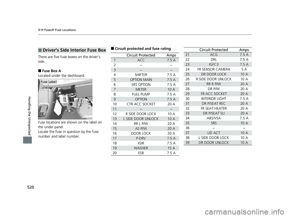
There are five fuse boxes on the driver’s
side.
■Fuse Box A
Located under the dashboard.
Fuse locations are shown on the label on
the under panel.
Locate the fuse in question by the fuse
number and label number.
■Driver’s Side Interior Fuse Box
Fuse Label
■Circuit protected and fuse rating
Circuit ProtectedAmps
1ACC7.5 A
2−−
3−−
4SHIFTER7.5 A
5OPTION MAIN7.5 A
6SRS OPTION7.5 A
7METER10 A
8FUEL PUMP7.5 A
9OPTION7.5 A
10CTR ACC SOCKET20 A
11−−
12R SIDE DOOR LOCK10 A
13L SIDE DOOR UNLOCK10 A
14RR L P/W20 A
15AS P/W20 A
16DOOR LOCK20 A
17P-DRV7.5 A
18IGIR7.5 A
19WASHER15 A
20ESB7.5 A
21ACG7.5 A
22DRL7.5 A
23IGFC37.5 A
24FR SENSOR CAMERA5A
25DR DOOR LOCK10 A
26R SIDE DOOR UNLOCK10 A
27RR R P/W20 A
28DR P/W20 A
29FR ACC SOCKET20 A
30INTERIOR LIGHT7.5 A
31DR P/SEAT REC20 A
32FR SEAT HEATER20 A
33DR P/SEAT SLI20 A
34ABS/VSA7.5 A
35SRS10 A
36−−
37LID ACT10 A
38L SIDE DOOR LOCK10 A
39DR DOOR UNLOCK10 A
Circuit ProtectedAmps
19 CLARITY FCV CSS-31TRT6200.book 520 ページ 2019年1月17日 木曜日 午前11 時54分