2019 FORD F650/750 service indicator
[x] Cancel search: service indicatorPage 107 of 387
Illumination of the service engine soon
indicator, charging system warning light or
the temperature warning light, fluid leaks,
strange odors, smoke or loss of engine
power could indicate that the emission
control system is not working properly.
An improperly operating or damaged
exhaust system may allow exhaust to
enter the vehicle. Have a damaged or
improperly operating exhaust system
inspected and repaired immediately.
Do not make any unauthorized changes to
your vehicle or engine. By law, vehicle
owners and anyone who manufactures,
repairs, services, sells, leases, trades
vehicles, or supervises a fleet of vehicles
are not permitted to intentionally remove
an emission control device or prevent it
from working. Information about your
vehicle
’s emission system is on the Vehicle
Emission Control Information Decal
located on or near the engine. This decal
also lists engine displacement.
Please consult your warranty information
for complete details.
On-Board Diagnostics (OBD-II)
Your vehicle has a computer known as the
on-board diagnostics system (OBD-II) that
monitors the engine ’s emission control
system. The system protects the
environment by making sure that your
vehicle continues to meet government
emission standards. The OBD-II system
also assists a service technician in properly
servicing your vehicle. When the service engine soon
indicator illuminates, the OBD-II
system has detected a
malfunction. Temporary malfunctions may
cause the service engine soon indicator to
illuminate. Examples are: 1. Your vehicle has run out of fuel
—the
engine may misfire or run poorly.
2. Poor fuel quality or water in the fuel —the engine may misfire or run
poorly.
3. The fuel fill inlet may not have closed properly. See Refueling (page 97).
4. Driving through deep water —the
electrical system may be wet.
You can correct these temporary
malfunctions by filling the fuel tank with
good quality fuel, properly closing the fuel
fill inlet or letting the electrical system dry
out. After three driving cycles without these
or any other temporary malfunctions
present, the service engine soon indicator
should stay off the next time you start the
engine. A driving cycle consists of a cold
engine startup followed by mixed city and
highway driving. No additional vehicle
service is required.
If the service engine soon indicator remains
on, have your vehicle serviced at the first
available opportunity. Although some
malfunctions detected by the OBD-II may
not have symptoms that are apparent,
continued driving with the service engine
soon indicator on can result in increased
emissions, lower fuel economy, reduced
engine and transmission smoothness and
lead to more costly repairs.
Readiness for Inspection and
Maintenance (I/M) Testing
Some state and provincial and local
governments may have
Inspection/Maintenance (I/M) programs
to inspect the emission control equipment
on your vehicle. Failure to pass this
inspection could prevent you from getting
a vehicle registration. If the service engine soon
indicator is on or the bulb does
not work, your vehicle may need
service. See On-Board Diagnostics.
104
F650750 (TBC) , enUSA, Edition date: 201804, Second-Printing Engine Emission Control
Page 108 of 387
Your vehicle may not pass the I/M test if
the service engine soon indicator is on or
not working properly (bulb is burned out),
or if the OBD-II system has determined
that some of the emission control systems
have not been properly checked. In this
case, the vehicle is not ready for I/M
testing.
If the vehicle
’s engine or transmission has
just been serviced, or the battery has
recently run down or been replaced, the
OBD-II system may indicate that the
vehicle is not ready for I/M testing. To
determine if the vehicle is ready for I/M
testing, turn the ignition key to the on
position for 15 seconds without cranking
the engine. If the service engine soon
indicator blinks eight times, it means that
the vehicle is not ready for I/M testing; if
the service engine soon indicator stays on
solid, it means that your vehicle is ready
for I/M testing.
The OBD-II system checks the emission
control system during normal driving. A
complete check may take several days.
If the vehicle is not ready for I/M testing,
you can perform the following driving cycle
consisting of mixed city and highway
driving:
1. 15 minutes of steady driving on an expressway or highway followed by 20
minutes of stop-and-go driving with at
least four 30-second idle periods.
2. Allow your vehicle to sit for at least eight hours with the ignition off. Then,
start the vehicle and complete the
above driving cycle. The vehicle must
warm up to its normal operating
temperature. Once started, do not turn
off the vehicle until the above driving
cycle is complete.
If the vehicle is still not ready for I/M
testing, you need to repeat the above
driving cycle. SELECTIVE CATALYTIC
REDUCTANT SYSTEM - DIESEL
Your vehicle may have a selective catalytic
reduction system. The system helps reduce
emission levels of oxides of nitrogen from
the exhaust system. The system
automatically injects diesel exhaust fluid
into the exhaust system to enable correct
selective catalytic reduction system
function.
Note:
Selective catalytic reduction systems
are not fitted to vehicles in markets where
only high-sulfur diesel fuel is available.
Diesel Exhaust Fluid Level
In order for the system to operate correctly
you must maintain the diesel exhaust fluid
level.
A warning message appears in the
information display when the diesel
exhaust fluid level is low. If a warning
message appears, refill the diesel exhaust
fluid tank as soon as possible. See
Information Messages (page 67).
Filling the Diesel Exhaust Fluid
Tank WARNING:
Keep diesel exhaust
fluid out of reach of children. Avoid
contact with skin, eyes or clothing. In
case of contact with your eyes, flush
immediately with water and get prompt
medical attention. In case of contact
with your skin, clean immediately with
soap and water. If you swallow any
diesel exhaust fluid, drink plenty of
water, call a physician immediately.
105
F650750 (TBC) , enUSA, Edition date: 201804, Second-Printing Engine Emission Control
Page 125 of 387
GENERAL INFORMATION
WARNING: Do not apply the brake
pedal and accelerator pedal
simultaneously. Applying both pedals
simultaneously for more than a few
seconds will limit engine performance,
which may result in difficulty maintaining
speed in traffic and could lead to serious
injury.
Note: Occasional brake noise is normal. If
a metal-to-metal, continuous grinding or
continuous squeal sound is present, the
brake linings may be worn-out. Have the
system checked as soon as possible. If your
vehicle has continuous vibration or shudder
in the steering wheel while braking, have it
checked by an authorized dealer.
All standard equipment brakes are
self-adjusting. Automatic adjustment,
when required, occurs whenever you apply
and release the brakes during forward or
reverse operation.
Know the required stopping distances for
all driving conditions you may encounter.
For longer brake lining life, take full
advantage of engine braking power when
coming to a stop.
Wet brakes result in reduced braking
efficiency. Gently press the brake pedal a
few times when driving from a car wash or
standing water to dry the brakes.
If the brakes do not grip well:
• Check brake adjustment.
• Check the brake linings for excessive
wear.
• Check the system air pressure on
vehicles with air brakes. •
Let the brakes cool if you have been
using them excessively, as in mountain
driving or after several fast, high-speed
stops.
• If you have been driving through deep
water, gently apply the brakes several
times while your vehicle is moving
slowly.
Brake Over Accelerator
In the event the accelerator pedal
becomes stuck or entrapped, apply steady
and firm pressure to the brake pedal to
slow the vehicle and reduce engine power.
If you experience this condition, apply the
brakes and bring your vehicle to a safe
stop. Move the transmission to park (P),
switch the engine off and apply the parking
brake. Inspect the accelerator pedal for
any interference. If none are found and the
condition persists, have your vehicle towed
to the nearest authorized dealer
Anti-lock Brake System
This system helps you maintain steering
control during emergency stops by keeping
the brakes from locking. This lamp momentarily
illuminates when you switch the
ignition on. If the light does not
illuminate during start up, remains on or
flashes, the system may be disabled. Have
the system checked by an authorized
dealer. If you connect a PLC trailer with
the ignition on, the trailer ABS
light also illuminates. If the light
fails to illuminate, if it remains on after you
start the vehicle or continues to flash, have
the system serviced immediately.
See
Warning Lamps and Indicators
(page 60).
122
F650750 (TBC) , enUSA, Edition date: 201804, Second-Printing Brakes E210335
Page 129 of 387
5. Tighten the nut until the spring is fully
caged and brakes released. Do not
loosen or remove the release stud and
nut unless you completely assemble
and securely clamp the brake chamber.
6. After restoring the air pressure, unscrew and remove the release stud
and install in the carrying pocket. Install
the access plug.
AIR BRAKES (IF EQUIPPED) WARNING:
Do not drive or
continue to drive if the low air pressure
buzzer is sounding or the brake warning
light is lit. These warnings indicate that
air pressure is not to normal operating
level. Continued use of the vehicle could
result in loss of braking ability. WARNING:
Avoid repeated light
application of the brake pedal. This
depletes air pressure faster and could
result in loss of braking capability. WARNING:
Do not move the
vehicle when the air pressure is
insufficient because the brake system
may be inoperative.
After starting the engine, give the air
compressor time to build up the air
pressure to
60 psi (414 kPa) before moving
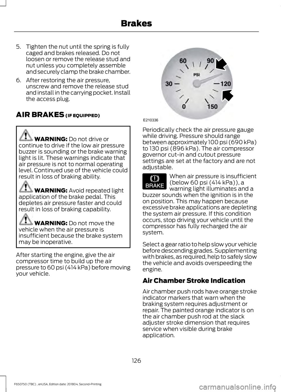
your vehicle. Periodically check the air pressure gauge
while driving. Pressure should range
between approximately 100 psi (690 kPa)
to
130 psi (896 kPa). The air compressor
governor cut-in and cutout pressure
settings are set at the factory and are not
adjustable. When air pressure is insufficient
(below
60 psi (414 kPa)), a
warning light illuminates and a
buzzer sounds when the ignition is in the
on position. This may happen because
excessive brake applications are depleting
the system air pressure. If this condition
occurs, stop driving your vehicle until the
compressor has fully recharged the air
system.
Select a gear ratio to help slow your vehicle
before descending grades. Supplementing
with brakes, as required, help to safely slow
the vehicle and avoids overspeeding the
engine.
Air Chamber Stroke Indication
Air chamber push rods have orange stroke
indicator markers that warn when the
braking system requires adjustment or
repair. The painted orange indicator is on
the air chamber push rod at the slack
adjuster stroke dimension that requires
service when visible during brake
application.
126
F650750 (TBC) , enUSA, Edition date: 201804, Second-Printing BrakesE210336 E206772
Page 136 of 387
PRINCIPLE OF OPERATION
The traction control system helps avoid
drive wheel spin and loss of traction.
If your vehicle begins to slide, the system
applies the brakes to individual wheels
and, when needed, reduces engine power
at the same time. If the wheels spin when
accelerating on slippery or loose surfaces,
the system reduces engine power in order
to increase traction.
Note:
The system does not apply the brakes
when vehicle speed is above 25 mph
(40 km/h).
USING TRACTION CONTROL -
VEHICLES WITH: AIR BRAKES WARNING:
The stability and
traction control light illuminates steadily
if the system detects a failure. Make sure
you did not manually disable the traction
control system using the information
display controls or the switch. If the
stability control and traction control light
is still illuminating steadily, have the
system serviced by an authorized dealer
immediately. Operating your vehicle with
the traction control disabled could lead
to an increased risk of loss of vehicle
control, vehicle rollover, personal injury
and death.
Press the TCS Off button to enable the
mud/snow mode.
This is beneficial when your vehicle is stuck
in snow or on a slippery road surface. This
mode allows wheel spin to dig your vehicle
out and allows you to rock your vehicle.
Press the switch again to select standard
traction control. The system automatically
selects standard traction control at the
next ignition cycle. System Indicator Light
Note:
If the traction control light does not
flash during a traction control event or stays
illuminated, the system is not functioning
properly. Take your vehicle to an authorized
dealer for service.
During traction control operation, the
traction control light flashes rapidly and
the engine does not rev-up when you press
further on the accelerator. This is normal
and is no reason for concern.
In Mud/Snow mode, the TCS OFF light
illuminates on the instrument cluster. If a
traction event occurs in either mode, the
Stability Control and Traction Control light
flashes rapidly.
USING TRACTION CONTROL -
VEHICLES WITH: HYDRAULIC
BRAKES WARNING:
Aggressive driving in
any road conditions can cause you to
lose control of your vehicle increasing
the risk of severe personal injury or
property damage. The occurrence of a
traction control event is an indication
that at least some of the tires have
exceeded their ability to grip the road;
this may lead to an increased risk of loss
of vehicle control, vehicle rollover,
personal injury and death. If you
experience a severe road event, SLOW
DOWN.
The system automatically turns on each
time you switch the ignition on.
Use the traction control switch on the
instrument panel to switch the system off
or on.
133
F650750 (TBC) , enUSA, Edition date: 201804, Second-Printing Traction Control
(If Equipped)
Page 137 of 387
If your vehicle is stuck in mud or snow,
switching traction control off may be
beneficial as this allows the wheels to spin.
Press the switch again to enable the
traction control system.
System Indicator Light
Note:
If the traction control light does not
flash during a traction control event or stays
illuminated, the system is not functioning
properly. Take your vehicle to an authorized
dealer for service.
During traction control operation, the
traction control light flashes rapidly and
the engine does not rev-up when you press
further on the accelerator. This is normal
and is no reason for concern.
When traction control is disabled, the
traction control light illuminates and
flashes slowly.
134
F650750 (TBC) , enUSA, Edition date: 201804, Second-Printing Traction Control (If Equipped)
Page 158 of 387
Vehicles Sold in Canada: Getting
Roadside Assistance
To fully assist you should you have a
vehicle concern, Ford Motor Company of
Canada, Limited offers a complimentary
roadside assistance program. This program
is eligible within Canada or the continental
United States.
The service is available 24 hours a day,
seven days a week.
This program is separate from the New
Vehicle Limited Warranty, but the coverage
is concurrent with the powertrain coverage
period of your vehicle. Canadian roadside
coverage and benefits may differ from the
U.S. coverage.
If you require more information, please call
us in Canada at 1-800-665-2006, or visit
our website at www.ford.ca.
HAZARD FLASHERS
Note:
If used when the vehicle is not
running, the battery loses charge. As a result,
there may be insufficient power to restart
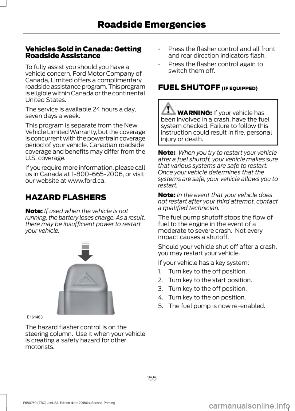
your vehicle. The hazard flasher control is on the
steering column. Use it when your vehicle
is creating a safety hazard for other
motorists. •
Press the flasher control and all front
and rear direction indicators flash.
• Press the flasher control again to
switch them off.
FUEL SHUTOFF (IF EQUIPPED) WARNING:
If your vehicle has
been involved in a crash, have the fuel
system checked. Failure to follow this
instruction could result in fire, personal
injury or death.
Note: When you try to restart your vehicle
after a fuel shutoff, your vehicle makes sure
that various systems are safe to restart.
Once your vehicle determines that the
systems are safe, your vehicle allows you to
restart.
Note: In the event that your vehicle does
not restart after your third attempt, contact
a qualified technician.
The fuel pump shutoff stops the flow of
fuel to the engine in the event of a
moderate to severe crash. Not every
impact causes a shutoff.
Should your vehicle shut off after a crash,
you may restart your vehicle.
If your vehicle has a key system:
1. Turn key to the off position.
2. Turn key to the start position.
3. Turn key to the off position.
4. Turn key to the on position.
5. The fuel pump is now re-enabled.
155
F650750 (TBC) , enUSA, Edition date: 201804, Second-Printing Roadside EmergenciesE161463
Page 199 of 387
4.
Make sure that the sealing surfaces on
the filter housing and cover are clean
and free of debris.
5. Install the new filter element.
6. Install the filter cover.
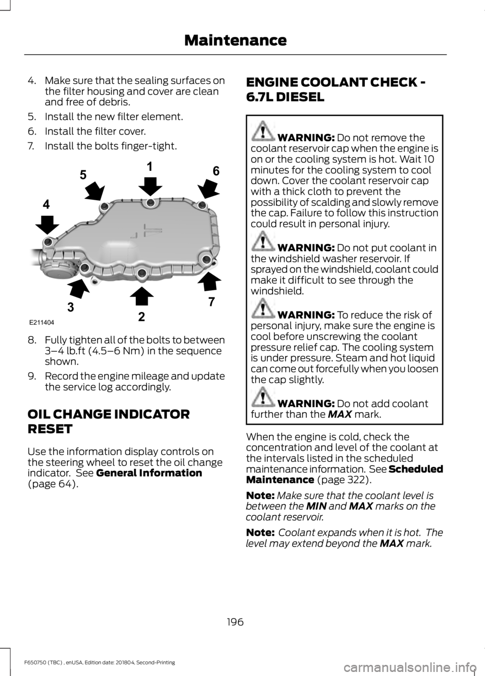
7. Install the bolts finger-tight. 8.
Fully tighten all of the bolts to between
3–4 lb.ft (4.5–6 Nm) in the sequence
shown.
9. Record the engine mileage and update
the service log accordingly.
OIL CHANGE INDICATOR
RESET
Use the information display controls on
the steering wheel to reset the oil change
indicator. See
General Information
(page 64). ENGINE COOLANT CHECK -
6.7L DIESEL WARNING:
Do not remove the
coolant reservoir cap when the engine is
on or the cooling system is hot. Wait 10
minutes for the cooling system to cool
down. Cover the coolant reservoir cap
with a thick cloth to prevent the
possibility of scalding and slowly remove
the cap. Failure to follow this instruction
could result in personal injury. WARNING:
Do not put coolant in
the windshield washer reservoir. If
sprayed on the windshield, coolant could
make it difficult to see through the
windshield. WARNING:
To reduce the risk of
personal injury, make sure the engine is
cool before unscrewing the coolant
pressure relief cap. The cooling system
is under pressure. Steam and hot liquid
can come out forcefully when you loosen
the cap slightly. WARNING:
Do not add coolant
further than the MAX mark.
When the engine is cold, check the
concentration and level of the coolant at
the intervals listed in the scheduled
maintenance information. See Scheduled
Maintenance
(page 322).
Note: Make sure that the coolant level is
between the
MIN and MAX marks on the
coolant reservoir.
Note: Coolant expands when it is hot. The
level may extend beyond the
MAX mark.
196
F650750 (TBC) , enUSA, Edition date: 201804, Second-Printing MaintenanceE211404
165
4
32
7