2019 FORD F650/750 headlamp
[x] Cancel search: headlampPage 91 of 387
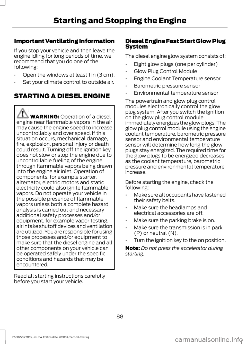
Important Ventilating Information
If you stop your vehicle and then leave the
engine idling for long periods of time, we
recommend that you do one of the
following:
•
Open the windows at least 1 in (3 cm).
• Set your climate control to outside air.
STARTING A DIESEL ENGINE WARNING: Operation of a diesel
engine near flammable vapors in the air
may cause the engine speed to increase
uncontrollably and over speed. If this
situation occurs, mechanical damage,
fire, explosion, personal injury or death
could result. Turning off the ignition key
does not slow or stop the engine due to
uncontrollable fueling of the engine
through flammable vapors being drawn
into the engine air inlet. Operation of
components, for example starter,
alternator, electric motors and static
electricity could also ignite flammable
vapors. Do not operate your vehicle in
the possible presence of flammable
vapors unless both a complete hazard
analysis is carried out and necessary
additional safety processes and/or
equipment, for example vapor testing,
air intake shutoff devices and ventilation
are utilized. You are responsible for using
those processes and/or equipment to
make sure that the diesel engine and all
other components on your vehicle can
be operated safely under the specific
conditions and hazards that may be
encountered.
Read all starting instructions carefully
before you start your vehicle. Diesel Engine Fast Start Glow Plug
System
The diesel engine glow system consists of:
•
Eight glow plugs (one per cylinder)
• Glow Plug Control Module
• Engine Coolant Temperature sensor
• Barometric pressure sensor
• Environmental temperature sensor
The powertrain and glow plug control
modules electronically control the glow
plug system. After you switch the ignition
on the glow plug control module
immediately energizes the glow plugs. The
glow plug control module using the engine
coolant temperature, barometric pressure
sensor and environmental temperature
sensor will determine how long the glow
plugs stay energized. The required time for
the glow plugs to be energized decreases
as the coolant temperature, barometric
pressure and environmental temperature
increase.
Before starting the engine, check the
following:
• Make sure all occupants have fastened
their safety belts.
• Make sure the headlamps and
electrical accessories are off.
• Make sure the parking brake is on.
• Make sure the transmission is in park
(P) or neutral (N).
• Turn the ignition key to the on position.
Note: Do not press the accelerator during
starting.
88
F650750 (TBC) , enUSA, Edition date: 201804, Second-Printing Starting and Stopping the Engine
Page 177 of 387
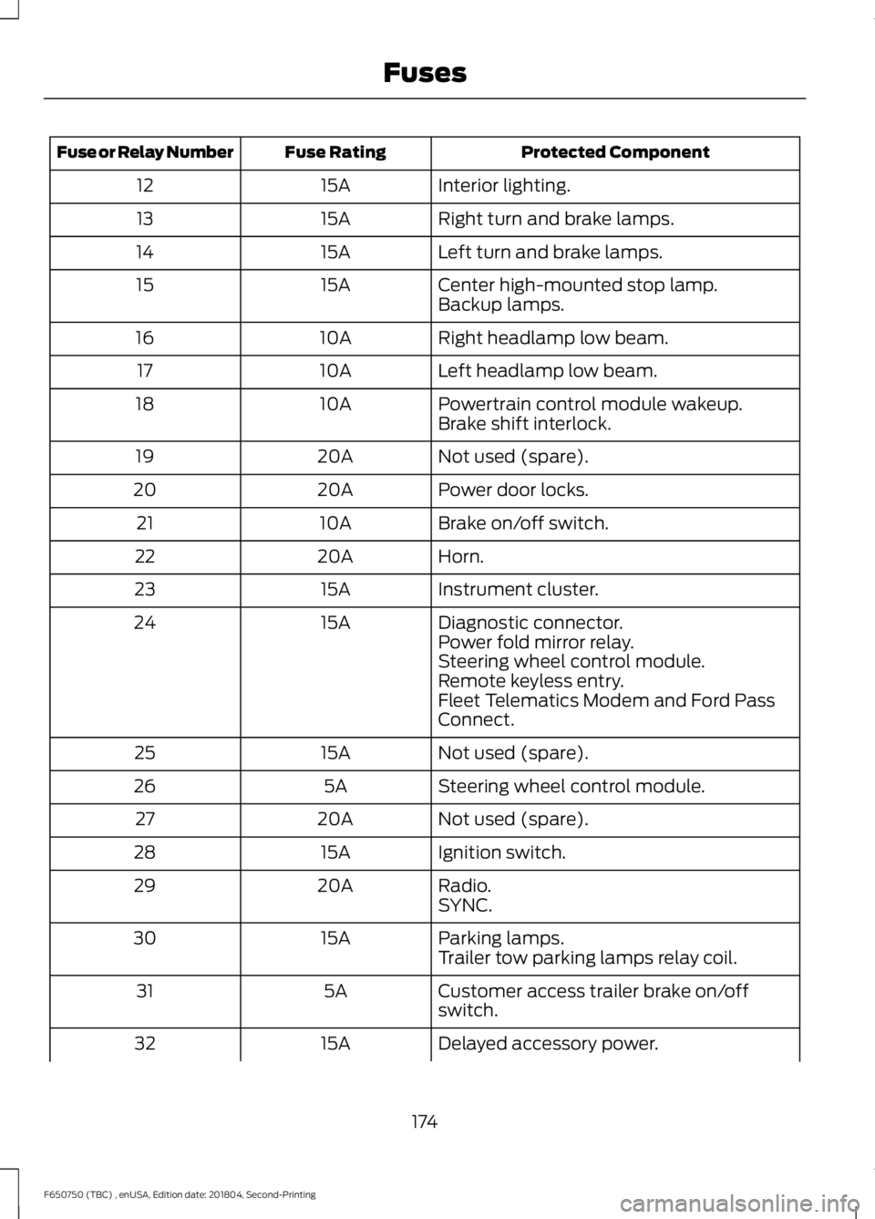
Protected Component
Fuse Rating
Fuse or Relay Number
Interior lighting.
15A
12
Right turn and brake lamps.
15A
13
Left turn and brake lamps.
15A
14
Center high-mounted stop lamp.
15A
15
Backup lamps.
Right headlamp low beam.
10A
16
Left headlamp low beam.
10A
17
Powertrain control module wakeup.
10A
18
Brake shift interlock.
Not used (spare).
20A
19
Power door locks.
20A
20
Brake on/off switch.
10A
21
Horn.
20A
22
Instrument cluster.
15A
23
Diagnostic connector.
15A
24
Power fold mirror relay.
Steering wheel control module.
Remote keyless entry.
Fleet Telematics Modem and Ford Pass
Connect.
Not used (spare).
15A
25
Steering wheel control module.
5A
26
Not used (spare).
20A
27
Ignition switch.
15A
28
Radio.
20A
29
SYNC.
Parking lamps.
15A
30
Trailer tow parking lamps relay coil.
Customer access trailer brake on/off
switch.
5A
31
Delayed accessory power.
15A
32
174
F650750 (TBC) , enUSA, Edition date: 201804, Second-Printing Fuses
Page 178 of 387
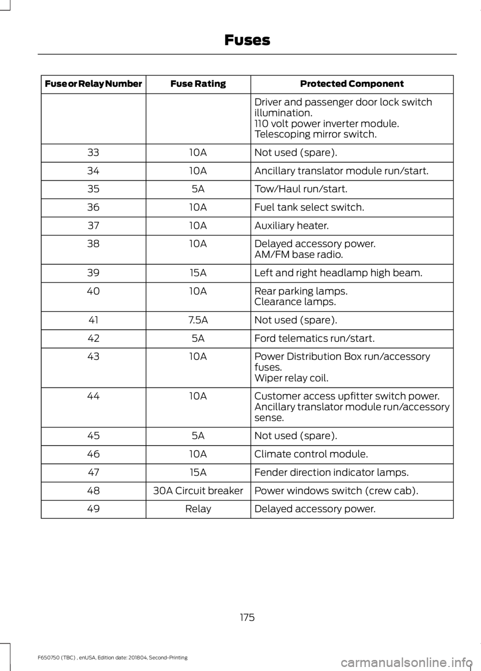
Protected Component
Fuse Rating
Fuse or Relay Number
Driver and passenger door lock switch
illumination.
110 volt power inverter module.
Telescoping mirror switch.
Not used (spare).
10A
33
Ancillary translator module run/start.
10A
34
Tow/Haul run/start.
5A
35
Fuel tank select switch.
10A
36
Auxiliary heater.
10A
37
Delayed accessory power.
10A
38
AM/FM base radio.
Left and right headlamp high beam.
15A
39
Rear parking lamps.
10A
40
Clearance lamps.
Not used (spare).
7.5A
41
Ford telematics run/start.
5A
42
Power Distribution Box run/accessory
fuses.
10A
43
Wiper relay coil.
Customer access upfitter switch power.
10A
44
Ancillary translator module run/accessory
sense.
Not used (spare).
5A
45
Climate control module.
10A
46
Fender direction indicator lamps.
15A
47
Power windows switch (crew cab).
30A Circuit breaker
48
Delayed accessory power.
Relay
49
175
F650750 (TBC) , enUSA, Edition date: 201804, Second-Printing Fuses
Page 213 of 387
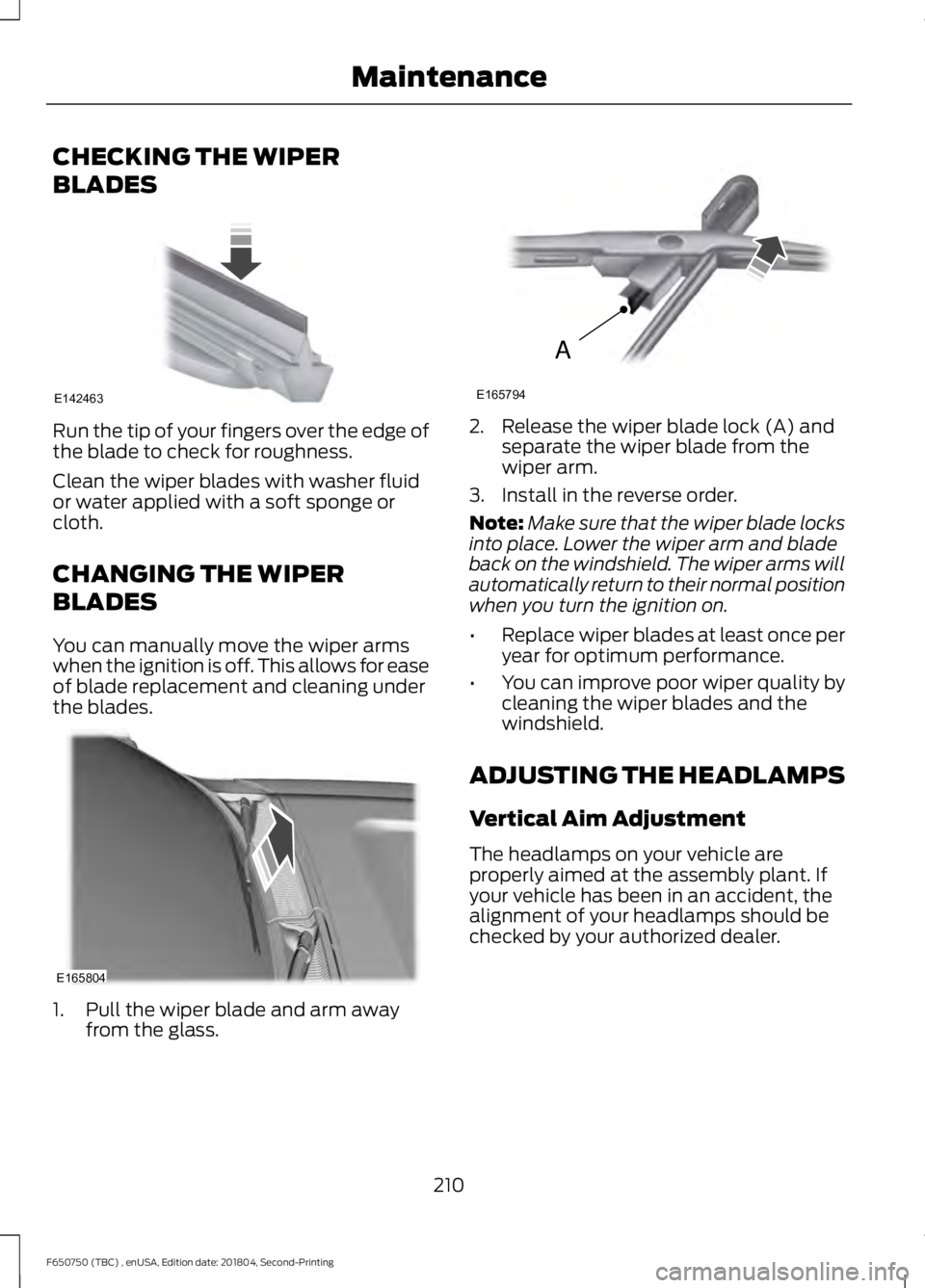
CHECKING THE WIPER
BLADES
Run the tip of your fingers over the edge of
the blade to check for roughness.
Clean the wiper blades with washer fluid
or water applied with a soft sponge or
cloth.
CHANGING THE WIPER
BLADES
You can manually move the wiper arms
when the ignition is off. This allows for ease
of blade replacement and cleaning under
the blades.
1. Pull the wiper blade and arm away
from the glass. 2. Release the wiper blade lock (A) and
separate the wiper blade from the
wiper arm.
3. Install in the reverse order.
Note: Make sure that the wiper blade locks
into place. Lower the wiper arm and blade
back on the windshield. The wiper arms will
automatically return to their normal position
when you turn the ignition on.
• Replace wiper blades at least once per
year for optimum performance.
• You can improve poor wiper quality by
cleaning the wiper blades and the
windshield.
ADJUSTING THE HEADLAMPS
Vertical Aim Adjustment
The headlamps on your vehicle are
properly aimed at the assembly plant. If
your vehicle has been in an accident, the
alignment of your headlamps should be
checked by your authorized dealer.
210
F650750 (TBC) , enUSA, Edition date: 201804, Second-Printing MaintenanceE142463 E165804 A
E165794
Page 214 of 387
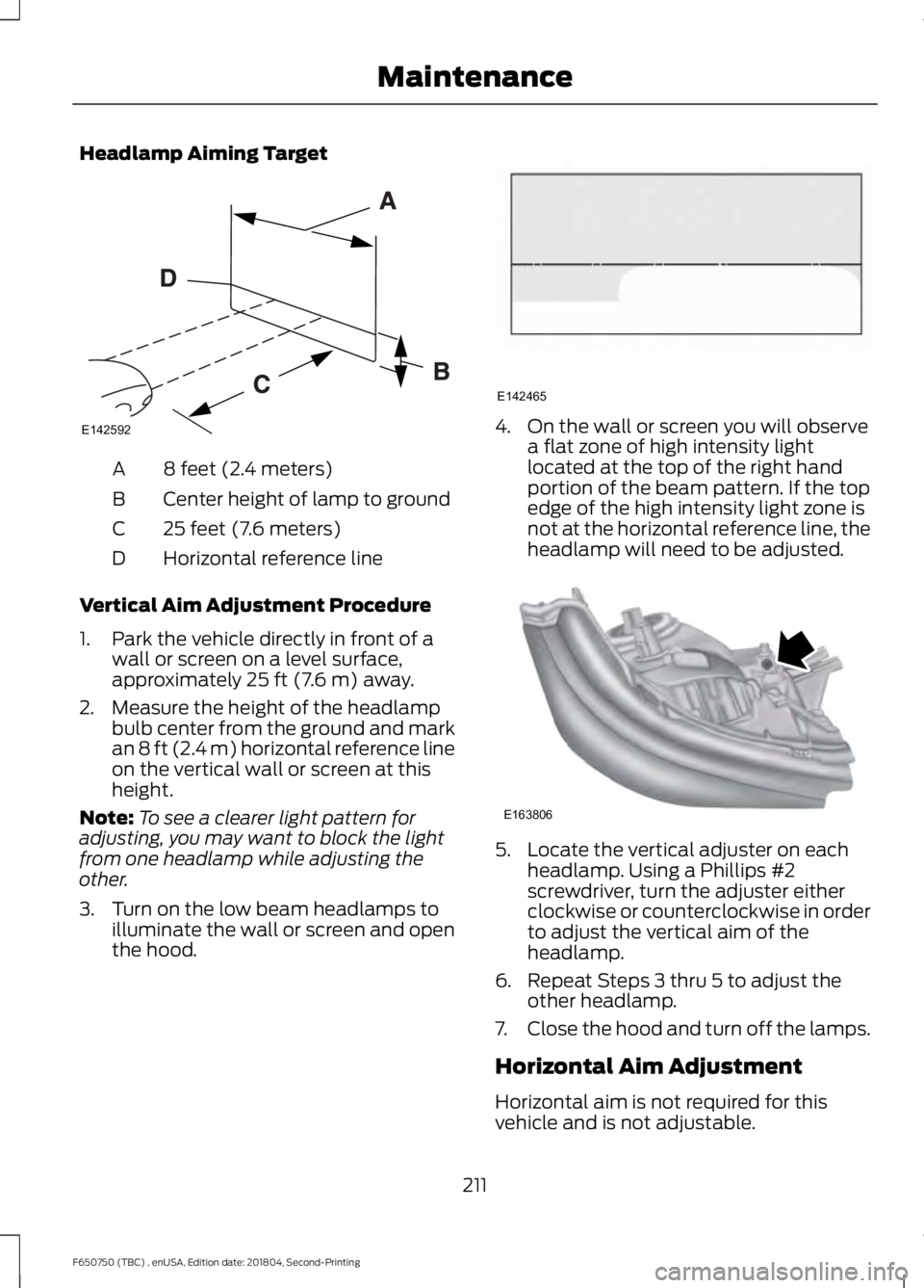
Headlamp Aiming Target
8 feet (2.4 meters)
A
Center height of lamp to ground
B
25 feet (7.6 meters)
C
Horizontal reference line
D
Vertical Aim Adjustment Procedure
1. Park the vehicle directly in front of a wall or screen on a level surface,
approximately 25 ft (7.6 m) away.
2. Measure the height of the headlamp bulb center from the ground and mark
an
8 ft (2.4 m) horizontal reference line
on the vertical wall or screen at this
height.
Note: To see a clearer light pattern for
adjusting, you may want to block the light
from one headlamp while adjusting the
other.
3. Turn on the low beam headlamps to illuminate the wall or screen and open
the hood. 4. On the wall or screen you will observe
a flat zone of high intensity light
located at the top of the right hand
portion of the beam pattern. If the top
edge of the high intensity light zone is
not at the horizontal reference line, the
headlamp will need to be adjusted. 5. Locate the vertical adjuster on each
headlamp. Using a Phillips #2
screwdriver, turn the adjuster either
clockwise or counterclockwise in order
to adjust the vertical aim of the
headlamp.
6. Repeat Steps 3 thru 5 to adjust the other headlamp.
7. Close the hood and turn off the lamps.
Horizontal Aim Adjustment
Horizontal aim is not required for this
vehicle and is not adjustable.
211
F650750 (TBC) , enUSA, Edition date: 201804, Second-Printing MaintenanceE142592 E142465 E163806
Page 215 of 387
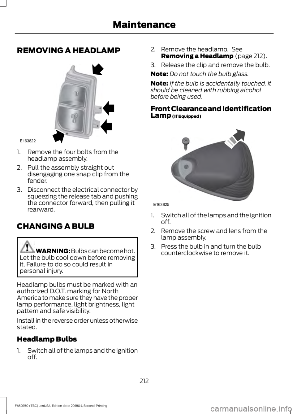
REMOVING A HEADLAMP
1. Remove the four bolts from the
headlamp assembly.
2. Pull the assembly straight out disengaging one snap clip from the
fender.
3. Disconnect the electrical connector by
squeezing the release tab and pushing
the connector forward, then pulling it
rearward.
CHANGING A BULB WARNING: Bulbs can become hot.
Let the bulb cool down before removing
it. Failure to do so could result in
personal injury.
Headlamp bulbs must be marked with an
authorized D.O.T. marking for North
America to make sure they have the proper
lamp performance, light brightness, light
pattern and safe visibility.
Install in the reverse order unless otherwise
stated.
Headlamp Bulbs
1. Switch all of the lamps and the ignition
off. 2. Remove the headlamp. See
Removing a Headlamp (page 212).
3. Release the clip and remove the bulb.
Note: Do not touch the bulb glass.
Note: If the bulb is accidentally touched, it
should be cleaned with rubbing alcohol
before being used.
Front Clearance and Identification
Lamp
(If Equipped) 1.
Switch all of the lamps and the ignition
off.
2. Remove the screw and lens from the lamp assembly.
3. Press the bulb in and turn the bulb counterclockwise to remove it.
212
F650750 (TBC) , enUSA, Edition date: 201804, Second-Printing MaintenanceE163822 E163825
Page 233 of 387
•
Dry your vehicle with a chamois or soft
terry cloth towel to eliminate water
spotting.
• Immediately remove fuel spillages, bird
droppings, insect deposits and road tar.
These may cause damage to your
vehicle ’s paintwork or trim over time.
We recommend Motorcraft Bug and
Tar Remover.
• Remove any exterior accessories, for
example antennas, before entering a
car wash.
• When filling with AdBlue®, remove any
residue on painted surfaces
immediately.
Note: Suntan lotions and insect repellents
can damage painted surfaces. If these
substances come in contact with your
vehicle, wash the affected area as soon as
possible.
Cleaning the Headlamps
Note: Do not scrape the headlamp lenses
or use abrasives, alcoholic solvents or
chemical solvents to clean them.
Note: Do not wipe the headlamps when
they are dry.
Exterior Chrome Parts
• Apply a high quality-cleaning product
to bumpers and other chrome parts.
Follow the manufacturer ’s instructions.
We recommend Motorcraft Custom
Bright Metal Cleaner.
• Do not apply the cleaning product to
hot surfaces. Do not leave the cleaning
product on chrome surfaces longer
than the time recommended.
• Using non-recommended cleaners can
result in severe and permanent
cosmetic damage.
Note: Never use abrasive materials, for
example steel wool or plastic pads as they
can scratch the chrome surface. Note:
Do not use chrome cleaner, metal
cleaner or polish on wheels or wheel covers.
Exterior Plastic Parts
For routine cleaning we recommend
Motorcraft Detail Wash. If tar or grease
spots are present, we recommend
Motorcraft Bug and Tar Remover.
Stripes or Graphics (If Equipped)
Hand washing your vehicle is preferred
however, pressure washing may be used
under the following conditions:
• Do not use water pressure higher than
2,000 psi (14,000 kPa)
.
• Do not use water hotter than
179°F
(82°C).
• Use a spray with a
40° wide spray
angle pattern.
• Keep the nozzle at a
12 in (305 mm)
distance and 90° angle to your
vehicle's surface.
Note: Holding the pressure washer nozzle
at an angle to the vehicle's surface may
damage graphics and cause the edges to
peel away from the vehicle's surface.
Underbody
Regularly clean the underside of your
vehicle using water. Keep body and door
drain holes free of debris or foreign
material.
Under Hood
For removing black rubber marks from
under the hood we recommend Motorcraft
Wheel and Tire Cleaner or Motorcraft Bug
and Tar Remover.
230
F650750 (TBC) , enUSA, Edition date: 201804, Second-Printing Vehicle Care
Page 278 of 387
BULB SPECIFICATION CHART
Replacement bulbs are specified in the
chart below. Headlamp bulbs must be
marked with an authorized
“D.O.T.” for
North America and an “E” for Europe to
ensure lamp performance, light brightness
and pattern and safe visibility. The correct
bulbs will not damage the lamp assembly
or void the lamp assembly warranty and
will provide quality bulb illumination time. Trade name
Number of Bulbs
Function
H13/9008
2
Headlamps
W5W
2
Side marker lamp - front
3157NA
2
Park/Turn lamp- front
3157
2
Tail/stop/turn/side marker
3157
2
Reverse
3157
1
License plate lamp
912
1
High-mount brake lamp
12V6W
2
Map lamp
578
3
Dome/reading lamps
275
F650750 (TBC) , enUSA, Edition date: 201804, Second-Printing Capacities and SpecificationsE240522