2019 FORD F650/750 change wheel
[x] Cancel search: change wheelPage 181 of 387
VEHICLE INSPECTION
INFORMATION
To make sure your vehicle is ready to
operate, conduct a pre-trip inspection at
the beginning of each work period. Follow
the steps listed in this section to verify a
proper vehicle inspection procedure.
WARNING: Exercise great caution
when working on a vehicle equipped with
an automatic fan clutch. The fan starts
in motion only after the engine coolant
reaches a predetermined temperature
or the refrigerant pressure (if equipped
with air conditioning) reaches a
predetermined setting. The fan starts at
this point with no advance warning.
Never reach near, or permit objects to
protrude into, the fan blade radius while
the engine is running as this could result
in vehicle damage, personal injury or
death. WARNING:
Do not operate the
vehicle if any suspension conditions
listed in the following charts are evident.
Loss of steering or suspension could
result in property damage, personal injury
or death. WARNING:
If a wheel must be
changed, obtain expert tire service help.
Mounting and un-mounting of tires
should only be performed by a qualified
technician using necessary safety
procedures and equipment, otherwise
the result could be property damage,
personal injury or death.
Note: Always make sure you apply the
parking brake before starting the engine. Engine compartment (with engine off)
Use the dipstick to verify the oil level is in the proper operating
range. See
Engine Oil Dipstick (page 192).
Engine oil
Look through the plastic reservoir and verify the coolant level
is within the proper operating range. Do not remove the
pressure cap until the coolant has cooled. See
Engine
Coolant Check (page 200).
Engine coolant
Verify that the fluid level is in the proper operating range. See
Power Steering Fluid Check
(page 206).
Power steering fluid
Remove the master cylinder caps and inspect the fluid level.
See
Brake Fluid Check (page 205).
Brake fluid
178
F650750 (TBC) , enUSA, Edition date: 201804, Second-Printing Vehicle Inspection Guide
Page 199 of 387
4.
Make sure that the sealing surfaces on
the filter housing and cover are clean
and free of debris.
5. Install the new filter element.
6. Install the filter cover.
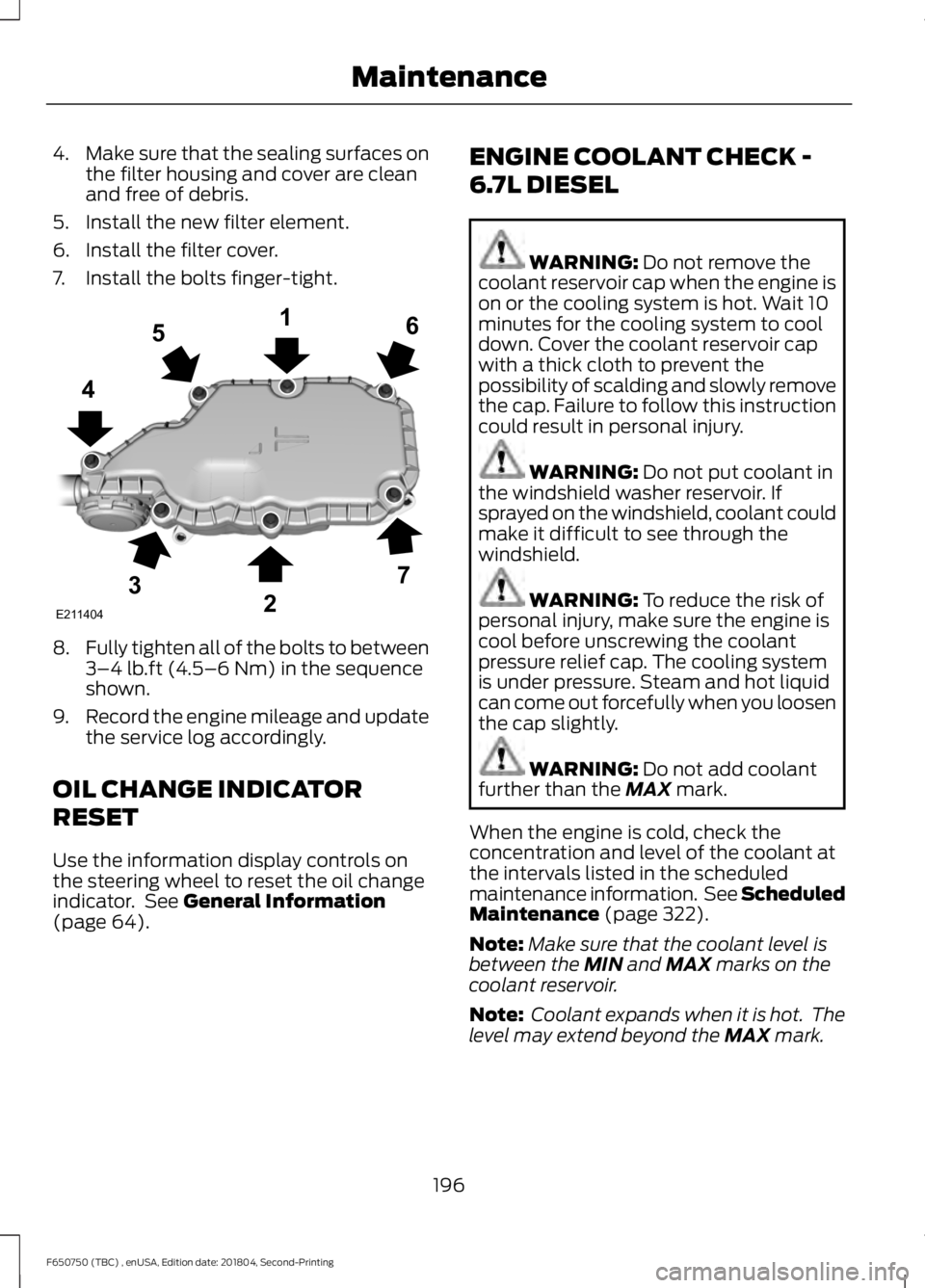
7. Install the bolts finger-tight. 8.
Fully tighten all of the bolts to between
3–4 lb.ft (4.5–6 Nm) in the sequence
shown.
9. Record the engine mileage and update
the service log accordingly.
OIL CHANGE INDICATOR
RESET
Use the information display controls on
the steering wheel to reset the oil change
indicator. See
General Information
(page 64). ENGINE COOLANT CHECK -
6.7L DIESEL WARNING:
Do not remove the
coolant reservoir cap when the engine is
on or the cooling system is hot. Wait 10
minutes for the cooling system to cool
down. Cover the coolant reservoir cap
with a thick cloth to prevent the
possibility of scalding and slowly remove
the cap. Failure to follow this instruction
could result in personal injury. WARNING:
Do not put coolant in
the windshield washer reservoir. If
sprayed on the windshield, coolant could
make it difficult to see through the
windshield. WARNING:
To reduce the risk of
personal injury, make sure the engine is
cool before unscrewing the coolant
pressure relief cap. The cooling system
is under pressure. Steam and hot liquid
can come out forcefully when you loosen
the cap slightly. WARNING:
Do not add coolant
further than the MAX mark.
When the engine is cold, check the
concentration and level of the coolant at
the intervals listed in the scheduled
maintenance information. See Scheduled
Maintenance
(page 322).
Note: Make sure that the coolant level is
between the
MIN and MAX marks on the
coolant reservoir.
Note: Coolant expands when it is hot. The
level may extend beyond the
MAX mark.
196
F650750 (TBC) , enUSA, Edition date: 201804, Second-Printing MaintenanceE211404
165
4
32
7
Page 237 of 387
If you intend on parking your vehicle for an
extended period after cleaning the wheels
with a wheel cleaner, drive your vehicle for
a few minutes before doing so. This
reduces the risk of corrosion of the brake
discs, brake pads and linings.
Do not clean the wheels when they are hot.
Note:
Some car washes could damage
wheel rims and covers.
Note: Using non-recommended cleaners,
harsh cleaning products, chrome wheel
cleaners or abrasive materials could
damage wheel rims and covers.
VEHICLE STORAGE
If you plan on storing your vehicle for 30
days or more, read the following
maintenance recommendations to make
sure your vehicle stays in good operating
condition.
We engineer and test all motor vehicles
and their components for reliable, regular
driving. Under various conditions,
long-term storage may lead to degraded
engine performance or failure unless you
use specific precautions to preserve engine
components.
General
• Store all vehicles in a dry, ventilated
place.
• Protect from sunlight, if possible.
• If vehicles are stored outside, they
require regular maintenance to protect
against rust and damage. Body
•
Wash your vehicle thoroughly to
remove dirt, grease, oil, tar or mud from
exterior surfaces, rear-wheel housing
and the underside of front fenders.
• Periodically wash your vehicle if it is
stored in exposed locations.
• Touch-up exposed or primed metal to
prevent rust.
• Cover chrome and stainless steel parts
with a thick coat of auto wax to prevent
discoloration. Re-wax as necessary
when you wash your vehicle.
• Lubricate all hood, door and luggage
compartment hinges and latches with
a light grade oil.
• Cover interior trim to prevent fading.
• Keep all rubber parts free from oil and
solvents.
Engine
• Change the engine oil and filter prior to
storage because used engine oil
contains contaminates which may
cause engine damage.
• Start the engine every 15 days for a
minimum of 15 minutes. Run at fast idle
with the climate controls set to defrost
until the engine reaches normal
operating temperature.
• With your foot on the brake, shift
through all the gears while the engine
is running.
• We recommend that you change the
engine oil before you use your vehicle
again.
Fuel system
• Fill the fuel tank with high-quality fuel
until the first automatic shutoff of the
fuel pump nozzle.
234
F650750 (TBC) , enUSA, Edition date: 201804, Second-Printing Vehicle Care
Page 240 of 387

Information on P Type Tires
P215/65R15 95H is an example of
a tire size, load index and speed
rating. The definitions of these
items are listed below. (Note that
the tire size, load index and speed
rating for your vehicle may be
different from this example.)
A.
P: Indicates a tire, designated
by the Tire and Rim Association,
that may be used for service on
cars, sport utility vehicles,
minivans and light trucks. Note:
If
your tire size does not begin with
a letter this may mean it is
designated by either the European
Tire and Rim Technical
Organization or the Japan Tire
Manufacturing Association. B.
215:
Indicates the nominal
width of the tire in millimeters
from sidewall edge to sidewall
edge. In general, the larger the
number, the wider the tire.
C. 65:
Indicates the aspect ratio
which gives the tire's ratio of
height to width.
D. R:
Indicates a radial type tire.
E. 15:
Indicates the wheel or rim
diameter in inches. If you change
your wheel size, you have to
purchase new tires to match the
new wheel diameter.
F. 95:
Indicates the tire's load
index. It is an index that relates to
how much weight a tire can carry.
Note: You may not find this
information on all tires because it
is not required by federal law.
G. H:
Indicates the tire's speed
rating. The speed rating denotes
the speed at which a tire is
designed to be driven for extended
periods of time under a standard
condition of load and inflation
pressure. The tires on your vehicle
may operate at different
conditions for load and inflation
pressure. These speed ratings may
need to be adjusted for the
difference in conditions. The
ratings range from
81– 186 mph
(130– 299 km/h). These ratings
are listed in the following chart.
Note: You may not find this
information on all tires because it
is not required by federal law.
237
F650750 (TBC) , enUSA, Edition date: 201804, Second-Printing Wheels and TiresH
I
J
KL
M
A
B
CDEFG
E142543
Page 244 of 387

C.
80: Indicates the aspect ratio
which gives the tire's ratio of
height to width. Numbers of 70 or
lower indicate a short sidewall.
D. D:
Indicates a diagonal type tire.
R:
Indicates a radial type tire.
E. 16:
Indicates the wheel or rim
diameter in inches. If you change
your wheel size, you have to
purchase new tires to match the
new wheel diameter.
Inflating Your Tires
Safe operation of your vehicle
requires that your tires are
properly inflated. Remember that
a tire can lose up to half of its air
pressure without appearing flat.
Every day before you drive, check
your tires. If one looks lower than
the others, use a tire gauge to
check pressure of all tires and
adjust if required.
At least once a month and before
long trips, inspect each tire and
check the tire pressure with a tire
gauge (including spare, if
equipped). Inflate all tires to the
inflation pressure recommended
by Ford Motor Company.
You are strongly urged to buy a
reliable tire pressure gauge, as
automatic service station gauges
may be inaccurate. Ford
recommends the use of a digital
or dial-type tire pressure gauge
rather than a stick-type tire
pressure gauge. Use the recommended cold
inflation pressure for optimum tire
performance and wear.
Under-inflation or over-inflation
may cause uneven treadwear
patterns
WARNING: Under-inflation
is the most common cause of
tire failures and may result in
severe tire cracking, tread
separation or blowout, with
unexpected loss of vehicle
control and increased risk of
injury. Under-inflation increases
sidewall flexing and rolling
resistance, resulting in heat
buildup and internal damage to
the tire. It also may result in
unnecessary tire stress, irregular
wear, loss of vehicle control and
accidents. A tire can lose up to
half of its air pressure and not
appear to be flat!
Always inflate your tires to the
Ford recommended inflation
pressure even if it is less than the
maximum inflation pressure
information found on the tire. The
Ford recommended tire inflation
pressure is found on the Safety
Compliance Certification Label or
Tire Label. Failure to follow the tire
pressure recommendations can
cause uneven treadwear patterns
and adversely affect the way your
vehicle handles.
241
F650750 (TBC) , enUSA, Edition date: 201804, Second-Printing Wheels and Tires
Page 245 of 387
Maximum Inflation Pressure is
the tire manufacturer's maximum
permissible pressure and the
pressure at which the maximum
load can be carried by the tire. This
pressure is normally higher than
the manufacturer ’s recommended
cold inflation pressure which can
be found on the Safety
Compliance Certification Label or
Tire Label. The cold inflation
pressure should never be set lower
than the recommended pressure
on the Safety Compliance
Certification Label or Tire Label.
When weather temperature
changes occur, tire inflation
pressures also change. A 10°F
(6°C) temperature drop can
cause a corresponding drop of
1 psi (7 kPa)
in inflation pressure.
Check your tire pressures
frequently and adjust them to the
proper pressure which can be
found on the Safety Compliance
Certification Label or Tire Label.
To check the pressure in your
tire(s):
1. Make sure the tires are cool, meaning they are not hot from
driving even a mile. Note:
If you are checking tire
pressure when the tire is hot, for
example, driven more than
1 mi
(1.6 km), never bleed or reduce air
pressure. The tires are hot from
driving and it is normal for
pressures to increase above
recommended cold pressures. A
hot tire at or below recommended
cold inflation pressure could be
significantly under-inflated.
Note: If you have to drive a
distance to get air for your tire(s),
check and record the tire pressure
first and add the appropriate air
pressure when you get to the
pump. It is normal for tires to heat
up and the air pressure inside to go
up as you drive.
2. Remove the cap from the valve
on one tire, then firmly press
the tire gauge onto the valve
and measure the pressure.
3. Add enough air to reach the
recommended air pressure.
Note: If you overfill the tire, release
air by pressing on the metal stem
in the center of the valve. Then
recheck the pressure with your tire
gauge.
4. Replace the valve cap.
5. Repeat this procedure for each
tire, including the spare.
242
F650750 (TBC) , enUSA, Edition date: 201804, Second-Printing Wheels and Tires
Page 254 of 387
USING SNOW CHAINS
WARNING: Snow tires must be
the same size, load index, and speed
rating as those originally provided by
Ford. Use of any tire or wheel not
recommended by Ford can affect the
safety and performance of your vehicle,
which could result in an increased risk of
loss of vehicle control, vehicle rollover,
personal injury, and death. Additionally,
the use of non-recommended tires and
wheels could cause steering, suspension,
axle, transfer case, or power transfer unit
failure. It is also strongly advised to
follow the Ford recommended tire
inflation pressure found on the Safety
Compliance Certification Label (affixed
to either the door hinge pillar, door-latch
post, or the door edge that meets the
door-latch post, next to the driver ’s
seating position), or Tire Label which is
located on the B-Pillar or the edge of the
driver door. Failure to follow the tire
pressure recommendations can cause
uneven treadwear patterns and
adversely affect the way your vehicle
handles.
The tires on your vehicle have all-weather
treads to provide traction in rain and snow.
However, in some climates, you may need
to use snow tires and cables. If you need
to use cables, it is recommended that steel
wheels (of the same size and
specifications) be used, as cables may chip
aluminum wheels.
Note: The suspension insulation and
bumpers help prevent vehicle damage. Do
not remove these components from your
vehicle when using snow tires and chains.
Follow these guidelines when using snow
tires and chains: •
If possible, avoid fully loading your
vehicle.
• Use only SAE Class S chains.
• Install chains securely, verifying that
the chains do not touch any wiring,
brake lines or fuel lines.
• Drive cautiously. If you hear the chains
rub or bang against your vehicle, stop
and retighten the chains. If this does
not work, remove the chains to prevent
damage to your vehicle.
• Remove the tire chains when they are
no longer needed. Do not use tire
chains on dry roads.
If you have any questions regarding snow
chains or cables, please contact your
authorized dealer.
CHANGING A ROAD WHEEL
If you get a flat tire while driving, do not
apply the brake heavily. Instead, gradually
decrease your speed. Hold the steering
wheel firmly and slowly move to a safe
place on the side of the road.
Tire Change Procedure WARNING:
When one of the front
wheels is off the ground, the
transmission alone will not prevent the
vehicle from moving or slipping off the
jack, even if the transmission is in park
(P). WARNING:
To help prevent the
vehicle from moving when you change
a tire, be sure to place the transmission
in park (P), set the parking brake and
block (in both directions) the wheel that
is diagonally opposite (other side and
end of the vehicle) to the tire being
changed.
251
F650750 (TBC) , enUSA, Edition date: 201804, Second-Printing Wheels and Tires
Page 255 of 387

WARNING: Never get underneath
a vehicle that is supported only by a jack.
If the vehicle slips off the jack, you or
someone else could be seriously injured. WARNING:
Do not attempt to
change a tire on the side of the vehicle
close to moving traffic. Pull far enough
off the road to avoid the danger of being
hit when operating the jack or changing
the wheel.
Note: Passengers should not remain in the
vehicle when the vehicle is being jacked.
Park on a level surface, set the parking
brake and activate the hazard flashers. 1.
Turn the engine off and block the wheel
that is diagonally opposite of the flat
tire using a wheel chock.
2. Loosen each wheel lug nut ½ turn counterclockwise, but do not remove
them until the wheel is raised off the
ground. 3.
Replace the flat tire with the spare tire,
making sure the valve stem is facing
outward on all front and inboard rear
wheels. If you are replacing the
outboard wheel, the valve stem must
be facing inward. Reinstall the lug nuts
until the wheel is snug against the hub.
Do not fully tighten the lug nuts until
the wheel has been lowered.
4. Lower the wheel and fully tighten the lug nuts in the order shown below. See
Technical Specifications (page 253).
5. Unblock the wheels. 8-lug nut torque sequence.
10-lug nut torque sequence.
252
F650750 (TBC) , enUSA, Edition date: 201804, Second-Printing Wheels and TiresE142551 E161441
13
4
27
6
5
8 1
2
3
4
5
6
7 8
9
10
E169375