2019 FORD F-350 ECU
[x] Cancel search: ECUPage 275 of 666

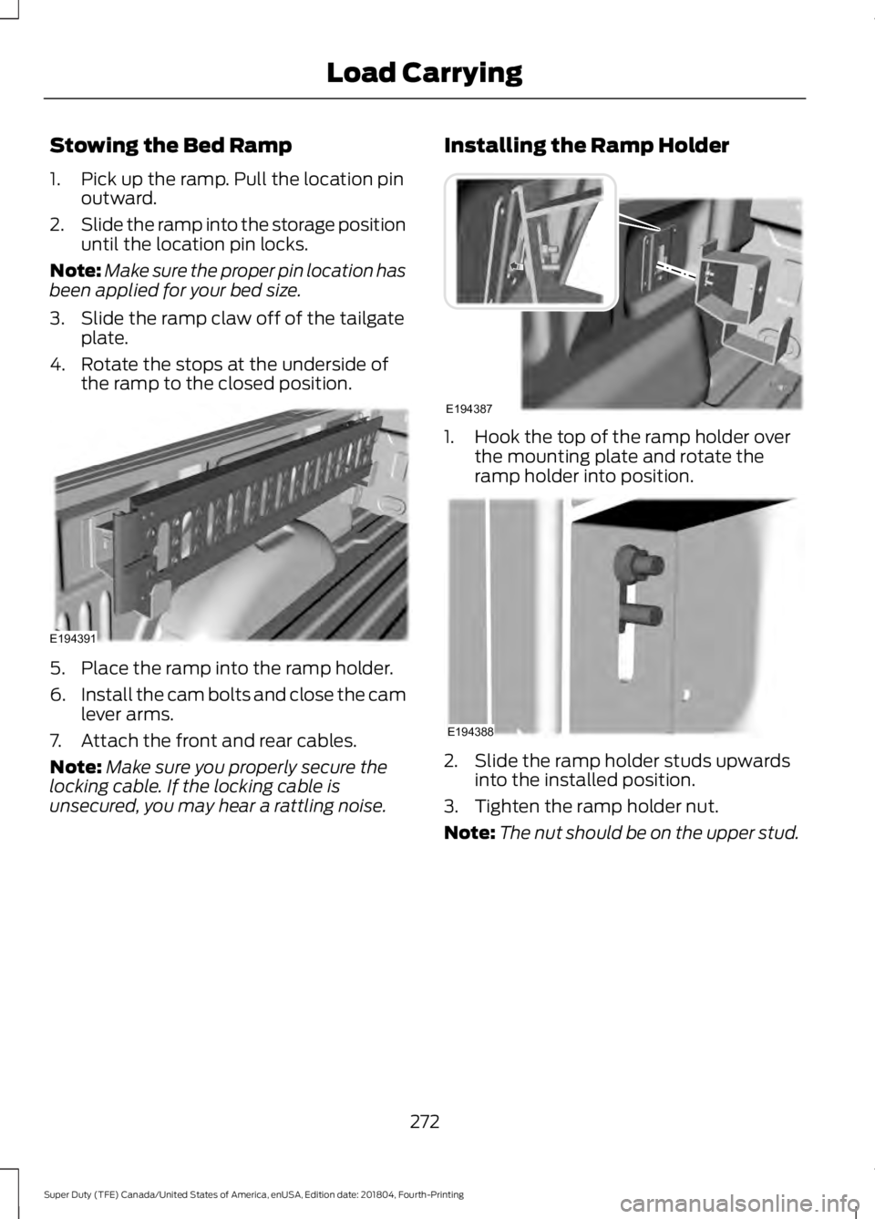
Stowing the Bed Ramp
1. Pick up the ramp. Pull the location pin
outward.
2. Slide the ramp into the storage position
until the location pin locks.
Note: Make sure the proper pin location has
been applied for your bed size.
3. Slide the ramp claw off of the tailgate plate.
4. Rotate the stops at the underside of the ramp to the closed position. 5. Place the ramp into the ramp holder.
6.
Install the cam bolts and close the cam
lever arms.
7. Attach the front and rear cables.
Note: Make sure you properly secure the
locking cable. If the locking cable is
unsecured, you may hear a rattling noise. Installing the Ramp Holder 1. Hook the top of the ramp holder over
the mounting plate and rotate the
ramp holder into position. 2. Slide the ramp holder studs upwards
into the installed position.
3. Tighten the ramp holder nut.
Note: The nut should be on the upper stud.
272
Super Duty (TFE) Canada/United States of America, enUSA, Edition date: 201804, Fourth-Printing Load CarryingE194391 E194387 E194388
Page 293 of 666

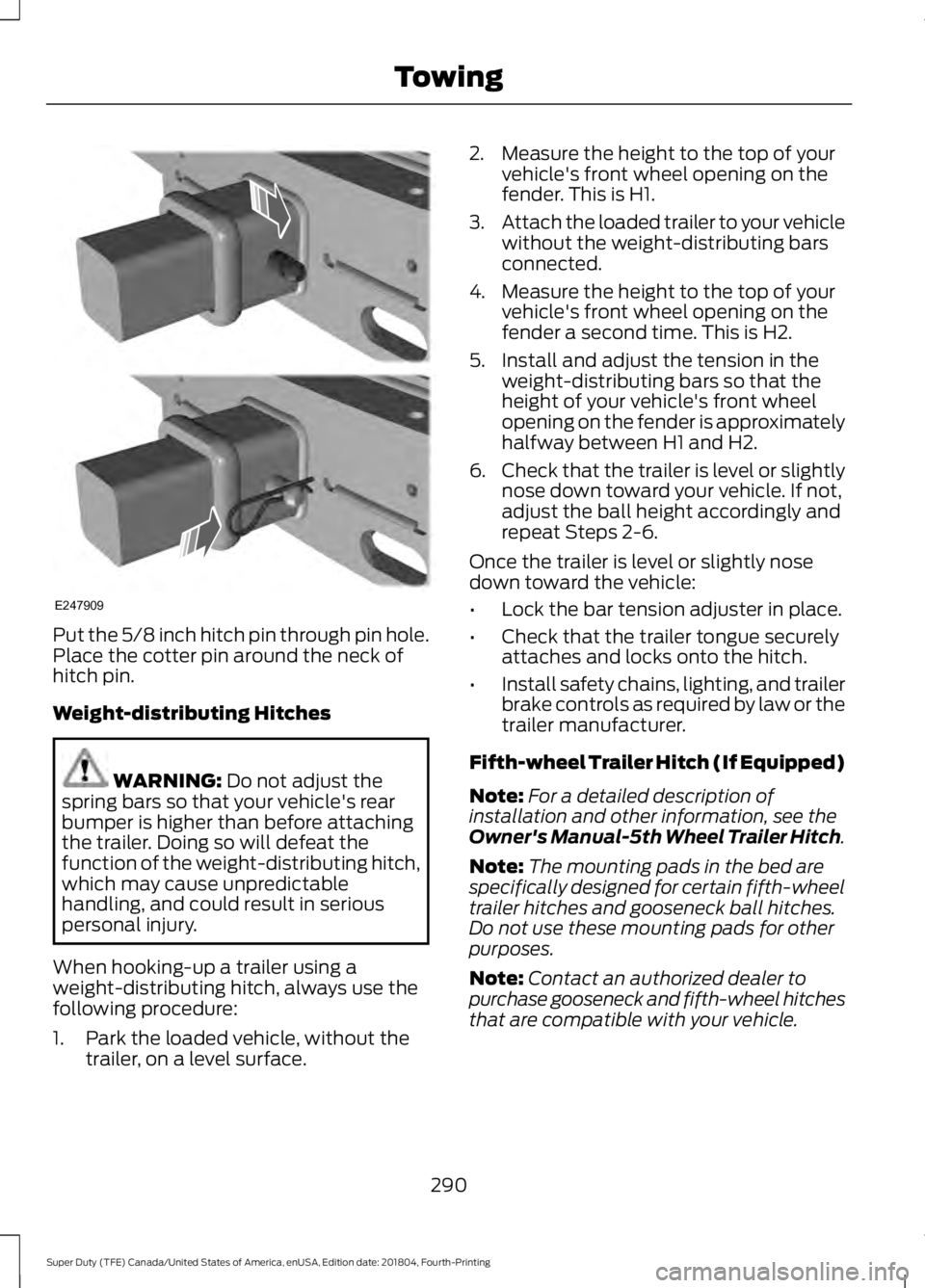
Put the 5/8 inch hitch pin through pin hole.
Place the cotter pin around the neck of
hitch pin.
Weight-distributing Hitches
WARNING: Do not adjust the
spring bars so that your vehicle's rear
bumper is higher than before attaching
the trailer. Doing so will defeat the
function of the weight-distributing hitch,
which may cause unpredictable
handling, and could result in serious
personal injury.
When hooking-up a trailer using a
weight-distributing hitch, always use the
following procedure:
1. Park the loaded vehicle, without the trailer, on a level surface. 2. Measure the height to the top of your
vehicle's front wheel opening on the
fender. This is H1.
3. Attach the loaded trailer to your vehicle
without the weight-distributing bars
connected.
4. Measure the height to the top of your vehicle's front wheel opening on the
fender a second time. This is H2.
5. Install and adjust the tension in the weight-distributing bars so that the
height of your vehicle's front wheel
opening on the fender is approximately
halfway between H1 and H2.
6. Check that the trailer is level or slightly
nose down toward your vehicle. If not,
adjust the ball height accordingly and
repeat Steps 2-6.
Once the trailer is level or slightly nose
down toward the vehicle:
• Lock the bar tension adjuster in place.
• Check that the trailer tongue securely
attaches and locks onto the hitch.
• Install safety chains, lighting, and trailer
brake controls as required by law or the
trailer manufacturer.
Fifth-wheel Trailer Hitch (If Equipped)
Note: For a detailed description of
installation and other information, see the
Owner's Manual-5th Wheel Trailer Hitch.
Note: The mounting pads in the bed are
specifically designed for certain fifth-wheel
trailer hitches and gooseneck ball hitches.
Do not use these mounting pads for other
purposes.
Note: Contact an authorized dealer to
purchase gooseneck and fifth-wheel hitches
that are compatible with your vehicle.
290
Super Duty (TFE) Canada/United States of America, enUSA, Edition date: 201804, Fourth-Printing TowingE247909
Page 300 of 666

Four-wheel Drive Vehicles Equipped
with a Manual-shift Transfer Case
1. Put the transmission in neutral (N).
2. Put the transfer case in neutral (N).
3.
Put the hub locks in the FREE position.
Always make sure that both hub locks
are set to the same position.
Four-wheel Drive Vehicles Equipped
with an Electronic-shift Transfer Case
Only tow a four-wheel drive vehicle that
has an electronic-shift transfer case with
all wheels on the ground. To do this, place
the transfer case in its neutral position and
engage the four-wheel-down towing
feature.
Perform the steps in the following section
after positioning your vehicle behind the
tow vehicle and properly securing them
together.
Note: Make sure you properly secure your
vehicle to the tow vehicle.
Four-wheel-down Towing
1. Put the ignition in the on position, but do not start the engine. If your vehicle
has an ignition key, turn the key to on.
If your vehicle has intelligent access,
press the engine START/STOP button
once without pressing the brake pedal.
2. Press and hold the brake pedal.
3. Rotate the four-wheel drive switch to 2H.
4. Shift the transmission to neutral (N).
5. Rotate the four-wheel drive switch from
2H to 4L and back to 2H five
times within seven seconds.
Note: If completed successfully, the
information display shows a message
indicating that your vehicle is safe to tow
with all wheels on the ground. Note:
If you do not see the message in the
display, you must perform the procedure
again from the beginning.
Note: You may hear an audible noise as the
transfer case shifts into its neutral position.
This is normal.
6. Leave the transmission in neutral (N) and turn the ignition as far as it will go
toward the off position (it will not turn
fully off when the transmission is in
neutral). If your vehicle has an ignition
key, you must leave the key in the
ignition while towing. To lock and
unlock your vehicle, use the keyless
entry keypad or extra set of keys. If your
vehicle has intelligent access, press the
engine
START/STOP button once
without pressing the brake pedal. You
do not need to leave your keys in the
vehicle. You can lock and unlock your
vehicle as you normally do.
7. Release the brake pedal. WARNING:
Do not disconnect the
battery during recreational towing. It
prevents the transfer case from shifting
properly and may cause the vehicle to
roll, even if the transmission is in park
(P). WARNING:
Shifting the transfer
case to its neutral position for
recreational towing may cause the
vehicle to roll, even if the transmission is
in park (P). It may injure the driver and
others. Make sure you press the foot
brake and the vehicle is in a secure, safe
position when you shift to neutral (N).
Note: Failing to put the transfer case in its
neutral position while towing with all four
wheels on the ground will damage vehicle
components.
297
Super Duty (TFE) Canada/United States of America, enUSA, Edition date: 201804, Fourth-Printing Towing
Page 301 of 666

Note:
You can check four-wheel-down
towing status at any time by opening the
driver's door or turning the ignition to the
accessory or on position and verifying a
message displays in the cluster.
To exit four-wheel-down towing and return
the transfer case to its 2H position:
1. With your vehicle still properly secured
to the tow vehicle, put the ignition in
the on position, but do not start the
engine. If your vehicle has an ignition
key, switch the key to on. If your vehicle
has intelligent access, press the engine
START/STOP
button once without
pressing the brake pedal.
2. Press and hold the brake pedal.
3. Shift the transmission out of neutral (N) and into any other gear.
4. Release the brake pedal.
Note: If completed successfully, the
2H
indicator light illuminates and a
confirmation message displays in the
instrument cluster.
Note: If the indicator light and message do
not display, you must perform the procedure
again from the beginning.
Note: You may hear an audible noise as the
transfer case shifts out of its neutral
position. This is normal.
Note: If a message displays in the
instrument cluster stating there is a shift
delay, transfer case gear tooth blockage
may be present. See
Resolving the Shift
Delay Issue after this section.
5. Apply the parking brake and disconnect
the vehicle from the tow vehicle.
6. Release the parking brake, start the engine and shift the transmission to
drive (D) to make sure the transfer
case is out of neutral (N). 7. If the transfer case does not
successfully shift out of neutral (N),
set the parking brake until you can have
your vehicle serviced.
Resolving the Shift Delay Issue
If the instrument cluster displays a shift
delay message, See
Information
Messages (page 128). You need to
perform the following steps:
1. Press and hold the brake pedal.
2. Put the transmission into neutral (N), and then start the engine.
3. With the engine running, shift the transmission to drive (D) and let the
vehicle roll forward, up to
3 ft (1 m).
You may hear an audible noise as the
transfer case shifts out of its neutral
position. This is normal.
4. When the issue is resolved, the instrument cluster displays a message
stating neutral tow is disabled.
298
Super Duty (TFE) Canada/United States of America, enUSA, Edition date: 201804, Fourth-Printing Towing
Page 303 of 666

•
Fuel economy may decrease with lower
temperatures during the first 5–10 mi
(12 –16 km) of driving.
• Driving on flat terrain offers improved
fuel economy as compared to driving
on hilly terrain.
• Transmissions give their best fuel
economy when operated in the top
cruise gear and with steady pressure
on the gas pedal.
• Four-wheel-drive operation (if
equipped) is less fuel efficient than
two-wheel-drive operation.
• Close the windows for high-speed
driving.
DRIVING THROUGH WATER WARNING:
Do not drive through
flowing or deep water as you may lose
control of your vehicle.
Note: Driving through standing water can
cause vehicle damage.
Note: Engine damage can occur if water
enters the air filter.
Before driving through standing water,
check the depth. Never drive through water
that is higher than the bottom of the wheel
hubs. When driving through standing water, drive
very slowly and do not stop your vehicle.
Your brake performance and traction may
be limited. After driving through water and
as soon as it is safe to do so:
•
Lightly press the brake pedal to dry the
brakes and to check that they work.
• Check that the horn works.
• Check that the exterior lights work.
• Turn the steering wheel to check that
the steering power assist works.
FLOOR MATS WARNING:
Use a floor mat
designed to fit the footwell of your
vehicle that does not obstruct the pedal
area. Failure to follow this instruction
could result in the loss of control of your
vehicle, personal injury or death. WARNING:
Pedals that cannot
move freely can cause loss of vehicle
control and increase the risk of serious
personal injury. WARNING:
Secure the floor mat
to both retention devices so that it
cannot slip out of position and interfere
with the pedals. Failure to follow this
instruction could result in the loss of
control of your vehicle, personal injury or
death. WARNING:
Do not place
additional floor mats or any other
covering on top of the original floor mats.
This could result in the floor mat
interfering with the operation of the
pedals. Failure to follow this instruction
could result in the loss of control of your
vehicle, personal injury or death.
300
Super Duty (TFE) Canada/United States of America, enUSA, Edition date: 201804, Fourth-Printing Driving HintsE176913
Page 304 of 666

WARNING: Always make sure that
objects cannot fall into the driver foot
well while your vehicle is moving. Objects
that are loose can become trapped
under the pedals causing a loss of
vehicle control. To install the floor mats, position the floor
mat eyelet over the retention post and
press down to lock in position.
To remove the floor mat, reverse the
installation procedure.
Note:
Regularly check the floor mats to
make sure they are secure.
SNOW PLOWING
Ford recommends that the Super Duty
F-Series used for snow removal include
the snowplow package option.
Installing the Snowplow
Weight limits and guidelines for selecting
and installing the snowplow are in the Ford
Truck Body Builders Layout Book,
snowplow section, found at
www.fleet.ford.com/truckbbas. A typical
installation affects the following: •
Certification to government safety laws
such as occupant protection and airbag
deployment, braking, and lighting. Look
for an Alterer ’s Label on the vehicle
from the snowplow installer certifying
that the installation meets all
applicable Federal Motor Vehicle
Safety Standards (FMVSS).
• The Total Accessory Reserve Capacity
(TARC) is on the lower right side of the
vehicle ’s Safety Compliance
Certification Label. This applies to
Ford-completed vehicles of 10,000 lb
(4,536 kg) GVWR or less. This is the
weight of permanently-attached
auxiliary equipment, such as snowplow
frame-mounting hardware, that can
be added to the vehicle and satisfy
Ford compliance certification to
FMVSS. Exceeding this weight may
require the auxiliary equipment installer
additional safety certification
responsibility. The Front Accessory
Reserve Capacity (FARC) is for
customer convenience.
• Rear ballast weight behind the rear
axle may be required to prevent
exceeding the FGAWR, and provide
front-to-rear weight balance for proper
braking and steering.
• Front wheel toe may require
re-adjustment to prevent premature
uneven tire wear. Specifications are in
the Ford Workshop Manual.
• Headlight aim may require
re-adjustment.
301
Super Duty (TFE) Canada/United States of America, enUSA, Edition date: 201804, Fourth-Printing Driving HintsE142666
Page 313 of 666

WARNING: Always slowly remove
the slack from the recovery strap prior
to pulling. Failure to do so can introduce
significantly higher loads which can
cause the recovery hooks to break off, or
the recovery strap to fail which can cause
serious injury or death. WARNING: Never link two straps
together with a clevis pin. These heavy
metal objects could become projectiles
if the strap breaks and can cause serious
injury or death.
Your vehicle comes equipped with
frame-mounted front recovery hooks.
These hooks should never have a load
applied to them greater than the gross
vehicle weight rating of your vehicle.
Before using recovery hooks:
• Make sure all attaching points are
secure and capable of withstanding
the applied load.
• Never use chains, cables or tow straps
with metal hook ends.
• Only use recovery straps that have a
minimum breaking strength two to
three times the gross vehicle weight of
the stuck vehicle.
• Make sure the recovery strap is in good
condition and free of visible cuts, tears
or damage.
• Use a damper device such as a tarp,
heavy blanket or piece of carpet
draped over the recovery strap to help
absorb the energy in the event the
strap breaks.
• Make sure the stuck vehicle is not
loaded heavier than its gross vehicle
weight rating specified on the
certification label. •
Always align the tow vehicle and stuck
vehicle in a straight line (within 10
degrees).
• Keep bystanders to the
sides of the
vehicle, at a distance of at least twice
the length of the recovery strap. This
helps avoid injury from the hazard of a
recovery hook or strap breaking, or a
vehicle lurching into their path.
310
Super Duty (TFE) Canada/United States of America, enUSA, Edition date: 201804, Fourth-Printing Roadside Emergencies
Page 315 of 666

2. If your inquiry or concern remains
unresolved, contact the Sales Manager,
Service Manager or Customer Relations
Manager.
3. If you require assistance or clarification
on Ford Motor Company policies,
please contact the Ford Customer
Relationship Center.
In order to help us serve you better, please
have the following information available
when contacting a Customer Relationship
Center:
• Vehicle Identification Number.
• Your telephone number (home and
business).
• The name of the authorized dealer and
city where located.
• The vehicle ’s current odometer reading.
In some states within the United States,
you must directly notify Ford in writing
before pursuing remedies under your
state's warranty laws, and Ford is also
allowed a final repair attempt.
Additionally, in some states within the
United States, a consumer has the option
of submitting a warranty dispute to the
BBB Auto Line before taking action under
the Magnuson-Moss Warranty Act, or to
the extent allowed by state law, before
pursuing replacement or repurchase
remedies provided by certain state laws.
This dispute handling procedure is not
required prior to enforcing state created
rights or other rights which are independent
of the Magnuson-Moss Warranty Act or
state replacement or repurchase laws. IN CALIFORNIA (U.S. ONLY)
California Civil Code Section 1793.2(d)
requires that, if a manufacturer or its
representative is unable to repair a motor
vehicle to conform to the vehicle
’s
applicable express warranty after a
reasonable number of attempts, the
manufacturer shall be required to either
replace the vehicle with one substantially
identical or repurchase the vehicle and
reimburse the buyer in an amount equal to
the actual price paid or payable by the
consumer (less a reasonable allowance
for consumer use). The consumer has the
right to choose whether to receive a refund
or replacement vehicle.
California Civil Code Section 1793.22(b)
presumes that the manufacturer has had
a reasonable number of attempts to
conform the vehicle to its applicable
express warranties if, within the first 18
months of ownership of a new vehicle or
the first 18,000 mi (29,000 km), whichever
occurs first:
1. Two or more repair attempts are made
on the same non-conformity likely to
cause death or serious bodily injury OR
2. Four or more repair attempts are made
on the same nonconformity (a defect
or condition that substantially impairs
the use, value or safety of the vehicle)
OR
3. The vehicle is out of service for repair of nonconformities for a total of more
than 30 calendar days (not necessarily
all at one time).
In the case of 1 or 2 above, the consumer
must also notify the manufacturer of the
need for the repair of the nonconformity
at the following address:
Ford Motor Company
16800 Executive Plaza Drive
Mail Drop 3NE-B
Dearborn, MI 48126
312
Super Duty (TFE) Canada/United States of America, enUSA, Edition date: 201804, Fourth-Printing Customer Assistance