2019 FIAT TIPO 4DOORS lock
[x] Cancel search: lockPage 83 of 252

WARNING
70)Never press button 3 when travelling.
71)Remember that, in the event of an
accident, the rear seat passengers not
wearing seat belts are exposed to a very
serious risk and also represent a serious
danger for the front seat occupants.
72)Make height adjustment of the seat
belts when the car is stationary.
73)After the height adjustment, always
check that the grip is locked in one of the
preset positions. To do this, with buttons
1 released, exert further pressure
downwards to allow the locking device to
click if the grip has not been released in
one of the possible positions.
SBR (SEAT BELT
REMINDER) SYSTEM
(for versions/markets, where provided)
The SBR system warns the passengers
of the front and rear (where provided)
seats if their seat belt is not fastened.
The system signals unfastened seat
belts with visual warnings (warning light
on the instrument panel and symbols
on the display) and an acoustic signal
(see the following paragraphs).
NOTE Contact a Fiat Dealership to
deactivate this acoustic warning
permanently. The acoustic warning can
be reactivated at any time through the
display Menu (see the "Display"
paragraph in the “Knowing the
instrument panel” chapter).
FRONT SEAT BELT
WARNING LIGHT
BEHAVIOUR
When the ignition device is turned to
MAR, the warning light
(see
fig. 74 for versions with multifunctional
display or fig. 75 for versions with
reconfigurable multifunctional display)
comes on for a few seconds,
regardless of the status of the front seat
belts.With vehicle at a standstill, if the driver
side seat belt or the passenger side
seat belt (for versions/markets, where
provided) is unfastened (with occupant
seated), the warning light stays on
constantly.
7406066J0001EM
75P2000037-000-000
81
Page 107 of 252

IMPORTANT
37)We recommend that during the initial
period, or during the first 1600 km, you do
not drive to full car performance (e.g.
excessive acceleration, long journeys at top
speed, sharp braking, etc.).
38)When the engine is switched off never
leave the ignition device in the MAR
position to prevent useless current
absorption from draining the battery.
39)A quick burst on the accelerator before
turning off the engine serves absolutely no
practical purpose; it wastes fuel and is
especially damaging to turbocharged
engines.
40)Warning light
will flash after starting
or during prolonged cranking to indicate a
fault with the glow plug heating system. If
the engine starts, the vehicle can be used
as normal, but a Fiat Dealership must be
contacted as soon as possible.
PARKING THE
VEHICLE
When parking and leaving the car,
proceed as follows:
engage a gear (1stgear if facing
uphill or reverse if facing downhill) and
leave the wheels turned;
stop the engine and engage the
handbrake;
always remove the ignition key.
Block the wheels with a wedge or a
stone if the car is parked on a steep
slope.
On versions equipped with automatic
transmission, wait for the letter P to be
displayed before releasing the brake
pedal.
IMPORTANTNEVERleave the car with
the gearbox in neutral (or, on versions
equipped with automatic transmission,
before placing the gear lever at P).
109)
WARNING
109)Never leave children unattended in
the car. Always remove the key from the
ignition when leaving the car and take it
with you.
PARKING BRAKE
110) 111)
To engage the handbrake, pull lever 1
fig. 97 upwards until the car is secured.
The
warning light will come on in
the instrument panel.
To disengage it, raise lever 1 slightly,
hold down button 2 and lower the lever
1, checking that the warning light
on the instrument panel switches
off.
WARNING
110)Never leave children unattended in
the car. Always remove the key from the
ignition when leaving the car and take it
with you.
97P07046J001
105
Page 110 of 252

Important notesDo not downshift on slippery
surfaces: the drive wheels might lose
grip with following risk for the vehicle to
slip. This could cause accidents or
personal injuries.
The vehicle will keep the gear
selected by the driver until the safety
conditions allow it. This means, for
example, that the system will try to
prevent the engine from switching off,
automatically downshifting if the engine
speed is too low.
TRANSMISSION
EMERGENCY FUNCTION
(where provided)
Transmission operation is constantly
monitored to detect any fault. If a
condition that might damage the
transmission is detected, the "recovery"
function is activated.
In this condition, the transmission stays
in 3
thgear, regardless of the selected
gear.
Positions P (Parking), R (Reverse) and N
(Neutral) still work. Icon
might light
up on the display.
In the case of "recovery" operation
immediately contact the nearest Fiat
Dealership.Temporary failure
In the event of a temporary failure,
correct transmission operation can be
restored for all the forwards gears by
proceeding as follows:
stop the vehicle;
bring the transmission lever to P
(Park);
bring the ignition device to STOP;
wait for about 10 seconds, then
restart the engine;
select the desired gear: correct
transmission operation should be
restored.
IMPORTANT In the event of a
temporary failure it is in any case
recommended to contact a Fiat
Dealership as soon as possible.
GEAR ENGAGEMENT
DISABLING SYSTEM
WITHOUT BRAKE PEDAL
PRESSED
This system prevents you from moving
the gear lever from position P (Park)
and N (Neutral) if the brake pedal has
not been previously depressed.
To bring the gear lever to a position
other than P (Park) or from N (Neutral)
to R (Reverse), the ignition device must
be in position MAR (engine on or off)
and the brake pedal must be
depressed. Button 1 fig. 99 on the gear
lever knob must also be pressed.To move the lever from position N
(Neutral) to position D (Drive, automatic
forward gear), you need to press the
brake pedal.
To facilitate parking manoeuvres, move
the lever from D to R (and vice versa)
without pressing the brake if the lever
does not pass through the N position.
The lever will remain locked in the P
position in case of faults or flat battery.
See the “Automatic transmission” in the
“In an emergency” chapter for how to
release the lever manually.
WARNING
113)Never use position P (Park) instead of
the parking brake. Always engage the
parking brake when parking the vehicle to
avoid the accidental movement of the
vehicle.
114)If the P (Park) position is not engaged,
the vehicle could move and injure people.
Before leaving the vehicle, make sure that
the gear lever is in position P and that the
parking brake is engaged.
115)Do not shift the gear lever to N
(Neutral) and do not stop the engine when
driving on a downhill road. This type of
driving is dangerous and reduces the
possibility of intervening in the case of
variation of the road traffic or surface. You
risk losing control of your vehicle and
causing accidents.
108
STARTING AND DRIVING
Page 122 of 252
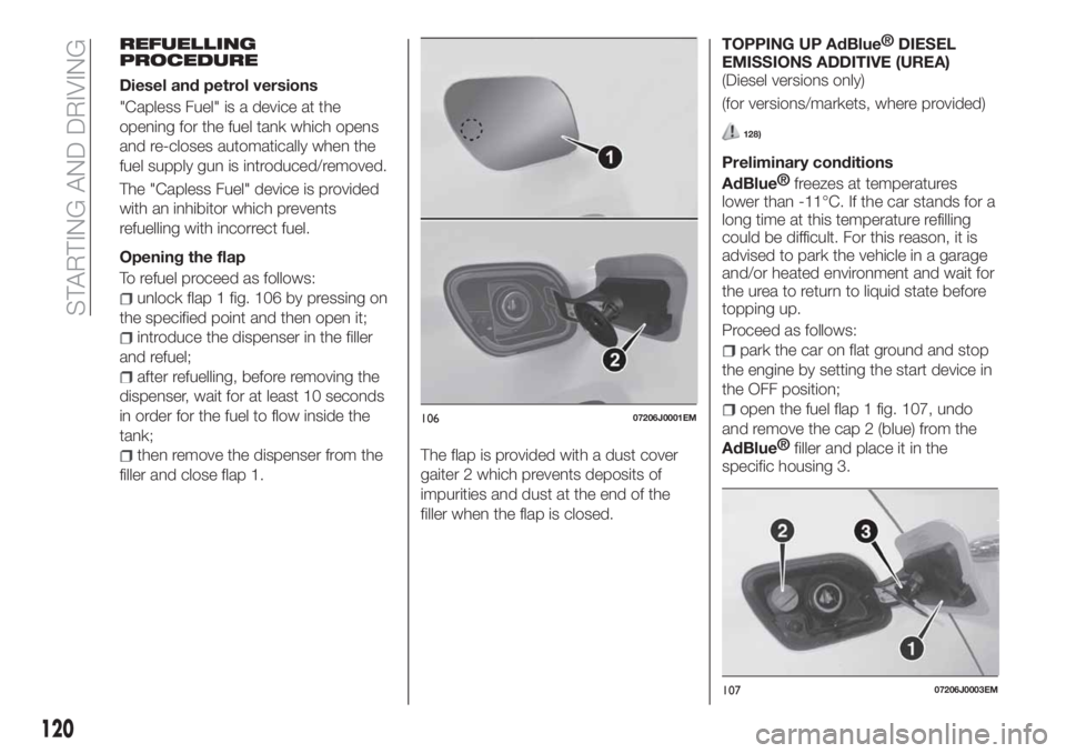
REFUELLING
PROCEDURE
Diesel and petrol versions
"Capless Fuel" is a device at the
opening for the fuel tank which opens
and re-closes automatically when the
fuel supply gun is introduced/removed.
The "Capless Fuel" device is provided
with an inhibitor which prevents
refuelling with incorrect fuel.
Opening the flap
To refuel proceed as follows:
unlock flap 1 fig. 106 by pressing on
the specified point and then open it;
introduce the dispenser in the filler
and refuel;
after refuelling, before removing the
dispenser, wait for at least 10 seconds
in order for the fuel to flow inside the
tank;
then remove the dispenser from the
filler and close flap 1.The flap is provided with a dust cover
gaiter 2 which prevents deposits of
impurities and dust at the end of the
filler when the flap is closed.TOPPING UP
AdBlue®
DIESEL
EMISSIONS ADDITIVE (UREA)
(Diesel versions only)
(for versions/markets, where provided)
128)
Preliminary conditions
AdBlue®
freezes at temperatures
lower than -11°C. If the car stands for a
long time at this temperature refilling
could be difficult. For this reason, it is
advised to park the vehicle in a garage
and/or heated environment and wait for
the urea to return to liquid state before
topping up.
Proceed as follows:
park the car on flat ground and stop
the engine by setting the start device in
the OFF position;
open the fuel flap 1 fig. 107, undo
and remove the cap 2 (blue) from the
AdBlue®
filler and place it in the
specific housing 3.
10607206J0001EM
10707206J0003EM
120
STARTING AND DRIVING
Page 123 of 252

Refilling with nozzles
You can fill up at any
AdBlue®
distributor.
Proceed as follows:
insert theAdBlue®
nozzle in the
filler, start refilling and stop refilling at
the first shut-off (the shut-off indicates
that the
AdBlue®
tank is full). Do not
proceed with the refilling, to prevent
spillage of
AdBlue®
;
extract the nozzle.
Refilling with containers
Proceed as follows:
check the expiration date;
read the advice for use on the label
before pouring the content of the bottle
into the
AdBlue®
tank;
if systems which cannot be screwed
in (e.g. tanks) are used for refilling, after
the indication appears on the
instrument panel display (see “Warning
lights and messages" paragraph in the
“Knowing the instrument panel”
chapter), fill the
AdBlue®
tank with no
more than 6 litres;
if containers which can be screwed
to the filler are used, the reservoir is full
when theAdBlue™level in the
container stops pouring out. Do not
proceed further.Operations after refilling
Proceed as follows:
fit the cap 2 fig. 107back on the
AdBlue®
filler by turning it clockwise
and screwing it completely;
set the ignition device to MAR (it is
not necessary to start the engine);
wait for the indication on the
instrument panel to switch off before
moving the car. The indication may stay
on for a few seconds to approximately
half a minute. If the engine is started
and the car is moved, the indication will
remain on for longer. This will not
compromise engine operation;
if theAdBlue®
was topped up when
the tank was empty, see the “Refuelling
” paragraph in the “Technical
Specifications” chapter and wait for
2 minutes before starting the engine.
IMPORTANT If AdBlue is spilled out of
the filler neck, clean up well the area
and proceed to filling up again. If the
liquid crystallises, eliminate it with a
sponge and warm water.
IMPORTANTDO NOT EXCEED THE MAXIMUM
LEVEL: this could cause damage to
the reservoir. UREA freezes at
under -11 °C. Although the system
is designed to operate below the
freezing point of the UREA, it is
advisable not to fill the tank beyondthe maximum level because if the
UREA freezes the system can be
damaged. Follow the instructions in
the “Topping up
AdBlue®
diesel
emissions additive (UREA)” paragraph
in this chapter.
If the UREA is spilled on painted
surfaces or aluminium, immediately
clean the area with water and use
absorbent material to collect the
fluid that has been spilled on the
ground.
Do not try to start the engine if
UREA was accidentally added to
the Diesel fuel tank, this can result
in serious engine damage, contact
a Fiat Dealership.
Do not add additives or other
fluids to
AdBlue®
, doing so could
damage the system.
The use of non-conforming or
degraded
AdBlue®
may lead to
indications appearing on the instrument
panel display (see “Warning lights and
messages" paragraph in the “Knowing
the instrument panel” chapter).
Never pourAdBlue®
into another
container: it could be contaminated.
If theAdBlue®
runs out, see
“Warning lights and messages"
paragraph in the “Knowing the
instrument panel” chapter to continue
using the car normally.
121
Page 129 of 252

TYPES OF BULBS
The vehicle is equipped with the following bulbs
Glass bulbs (type 1): they are press-fitted. Pull to extract.
Bayonet-type bulbs (type 2): to remove them from their holder,
press the bulb and turn it anticlockwise, then extract it.
Halogen bulbs (type 3): to remove the bulb, pull the connector and
extract it.
Halogen bulbs (type 4): to remove the bulb, turn it anticlockwise.
Xenon gas discharge bulb (type 5):
(for versions/markets, where provided)
to remove the bulb, contact a Fiat Dealership.
127
Page 132 of 252

steer the car wheels completely
inwards;
undo screw 1 fig. 114 using the
screwdriver provided and remove
inspection flap 2;
turn the bulb-bulb holder assembly 1
fig. 115 anticlockwise and then remove
it sliding it outwards;
disconnect the electrical connector;
reconnect the connector to the new
assembly: then insert it, turning it
clockwise, ensuring that it locks
correctly;
finally, refit the inspection flap.
Main beam headlights/Daytime
running lights (DRL)
To replace the bulb 3 fig. 112, proceed
as follows:
working from inside the engine
compartment, remove rubber cap 1
fig. 116;
rotate the bulb-bulb holder assembly
anticlockwise and extract it;
disconnect the electrical connector
and replace the bulb-bulb holder
assembly 2;
reconnect the electrical connector to
the new assembly;
then insert the assembly in its
housing and turn it clockwise, making
sure that it is locked correctly;
refit the rubber cap 1.
IMPORTANT Only replace the bulb
when the engine is off. Also ensure that
the engine is cold, to prevent the risk of
burns.
Front direction indicators
To replace the bulb 4 fig. 112, proceed
as follows:
rotate the bulb-bulb holder assembly
anticlockwise;
replace the "bayonet-fitted" bulb;
then insert the bulb-bulb holder
assembly in its housing and turn it
clockwise, making sure that it is locked
correctly.
Side turn light
To replace the bulb, proceed as follows:
adjust the lens 1 fig. 117 to
compress in the internal clip 2, then pull
the cluster outwards;
turn the bulb holder 3 anticlockwise,
extract the press-fitted bulb 4 and
replace it;
refit the bulb holder 3 in the lens and
turn it clockwise;
refit the cluster making sure that the
internal clip 2 clicks into position.
11508026J0016EM11608026J0025EM
11708026J0005EM
130
IN AN EMERGENCY
Page 133 of 252

Versions with Xenon gas discharge
headlights
Main/dipped beam headlights
(for versions/markets, where provided)
For replacing these bulbs, contact a
Fiat Dealership.
Rear bulb position
1. Tail lights/Brake lights
2. Direction indicator
3. Reverse gear
4. Rear fog light
Rear light cluster
To replace the bulbs, proceed as
follows:
open the rear lid and move the cover
on the inner trim 5 fig. 119;
disconnect the central electric
connector 6, operating on the
dedicated retainer, then unscrew the
screw 7 fig. 120;
remove the rear light cluster, pulling it
outwards as indicated in fig. 121;
to replace the rear fog light bulb, turn
the bulb holder 8 fig. 122 anticlockwise
and replace the bulb, extracting it from
its bulb holder;
to replace the other lamps, unscrew
the four fixing screws fig. 122 and
remove the bulb holder;
11808026J0006EM
11908026J0007EM
12008026J0008EM
12108026J0017EM
122P08026J0018
131