2019 FIAT 500E flat tire
[x] Cancel search: flat tirePage 176 of 300

Gross Axle Weight Rating (GAWR)
The GAWR is the maximum permissible load on the front
and rear axles. The load must be distributed in the cargo
area so that the GAWR of each axle is not exceeded.
Each axle GAWR is determined by the components in the
system with the lowest load carrying capacity (axle,
springs, tires or wheels). Heavier axles or suspension
components sometimes specified by purchasers for in-
creased durability does not necessarily increase the vehi-
cle’s GVWR.
Tire Size
The tire size on the Vehicle Certification Label represents
the actual tire size on your vehicle. Replacement tires must
be equal to the load capacity of this tire size.
Rim Size
This is the rim size that is appropriate for the tire size
listed.
Inflation Pressure
This is the cold tire inflation pressure for your vehicle for
all loading conditions up to full GAWR.
Curb Weight
The curb weight of a vehicle is defined as the total weight
of the vehicle with all fluids at full capacity conditions, and
with no occupants or cargo loaded into the vehicle. The
front and rear curb weight values are determined by
weighing your vehicle on a commercial scale before any
occupants or cargo are added.
Loading
The actual total weight and the weight of the front and rear
of your vehicle at the ground can best be determined by
weighing it when it is loaded and ready for operation.
The entire vehicle should first be weighed on a commercial
scale to insure that the GVWR has not been exceeded. The
weight on the front and rear of the vehicle should then be
determined separately to be sure that the load is properly
distributed over the front and rear axle. Weighing the
vehicle may show that the GAWR of either the front or rear
axles has been exceeded but the total load is within the
specified GVWR. If so, weight must be shifted from front to
rear or rear to front as appropriate until the specified
weight limitations are met. Store the heavier items down
low and be sure that the weight is distributed equally. Stow
all loose items securely before driving.
174 STARTING AND OPERATING
Page 179 of 300

•Keep tires properly inflated.
• Maintain sufficient distance between your vehicle and
the vehicle in front of you to avoid a collision in a
sudden stop.
Driving Through Water
Driving through water more than a few inches/centimeters
deep will require extra caution to ensure safety and pre-
vent damage to your vehicle.
Flowing/Rising Water
WARNING!
Do not drive on or across a road or path where water is
flowing and/or rising (as in storm run-off). Flowing
water can wear away the road or path’s surface and
cause your vehicle to sink into deeper water. Further-
more, flowing and/or rising water can carry your ve-
hicle away swiftly. Failure to follow this warning may
result in injuries that are serious or fatal to you, your
passengers, and others around you.
Shallow Standing Water
Although your vehicle is capable of driving through shal-
low standing water, consider the following Caution and
Warning before doing so.
CAUTION!
• Always check the depth of the standing water before
driving through it. Never drive through standing
water that is deeper than the bottom of the tire rims
mounted on the vehicle.
• Determine the condition of the road or the path that
is under water and if there are any obstacles in the
way before driving through the standing water.
• Do not exceed 5 mph (8 km/h) when driving through
standing water. This will minimize wave effects.
• Driving through standing water may cause damage
to your vehicle’s drivetrain components. Always in-
spect your vehicle’s fluids (i.e., transmission, coolant,
etc.) for signs of contamination (i.e., fluid that is
milky or foamy in appearance) after driving through
standing water. Do not continue to operate the ve-
hicle if any fluid appears contaminated, as this may
(Continued)
6
STARTING AND OPERATING 177
Page 180 of 300

CAUTION!(Continued)
result in further damage. Such damage is not covered
by the New Vehicle Limited Warranty.
• Driving through standing water limits your vehicle’s
traction capabilities. Do not exceed 5 mph (8 km/h)
when driving through standing water.
• Driving through standing water limits your vehicle’s
braking capabilities, which increases stopping dis-
tances. Therefore, after driving through standing
water, drive slowly and lightly press on the brake
pedal several times to dry the brakes.
• Failure to follow these warnings may result in inju-
ries that are serious or fatal to you, your passengers,
and others around you.
EXTENDING YOUR DRIVING RANGE PER CHARGE
The drive system and cabin temperature management
features use the most energy from the high voltage battery.
Reducing energy draw from these features are the easiest
and most effective way to extend driving range. The 500e uses high voltage components to heat and cool
the cabin, so when using automatic climate control, con-
sider setting temperatures a few degrees higher or lower
during hot and cold days. If your 500e has been soaking in
hot or cold temperatures for an extended period, it is
recommended that the car be preconditioned using the
Uconnect smartphone app (not available in Canada) while
still plugged into a charging source. This will allow 500e to
use external power to establish a comfortable cabin tem-
perature before the drive and allow the battery to maintain
the temperature at significantly lower energy levels.
Additional tips:
•
Keep tires properly inflated.
• When practical, choose surface streets over the highway,
and work to maintain a steady speed.
• Avoid carrying nonessential cargo.
• Be mindful of adding external accessories that may
increase aerodynamic drag.
• Perform all scheduled maintenance at recommended
intervals.
178 STARTING AND OPERATING
Page 197 of 300
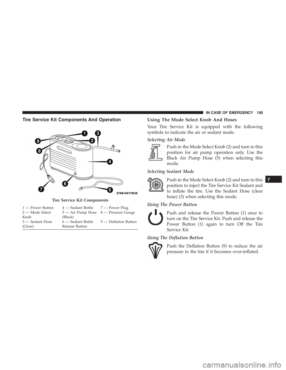
Tire Service Kit Components And OperationUsing The Mode Select Knob And Hoses
Your Tire Service Kit is equipped with the following
symbols to indicate the air or sealant mode.
Selecting Air Mode
Push in the Mode Select Knob (2) and turn to this
position for air pump operation only. Use the
Black Air Pump Hose (5) when selecting this
mode.
Selecting Sealant Mode
Push in the Mode Select Knob (2) and turn to this
position to inject the Tire Service Kit Sealant and
to inflate the tire. Use the Sealant Hose (clear
hose) (3) when selecting this mode.
Using The Power Button
Push and release the Power Button (1) once to
turn on the Tire Service Kit. Push and release the
Power Button (1) again to turn Off the Tire
Service Kit.
Using The Deflation Button
Push the Deflation Button (9) to reduce the air
pressure in the tire if it becomes over-inflated.
Tire Service Kit Components
1 — Power Button 4 — Sealant Bottle 7 — Power Plug
2 — Mode Select
Knob 5 — Air Pump Hose
(Black)8 — Pressure Gauge
3 — Sealant Hose
(Clear) 6 — Sealant Bottle
Release Button9 — Deflation Button
7
IN CASE OF EMERGENCY 195
Page 198 of 300
Tire Service Kit Usage Precautions
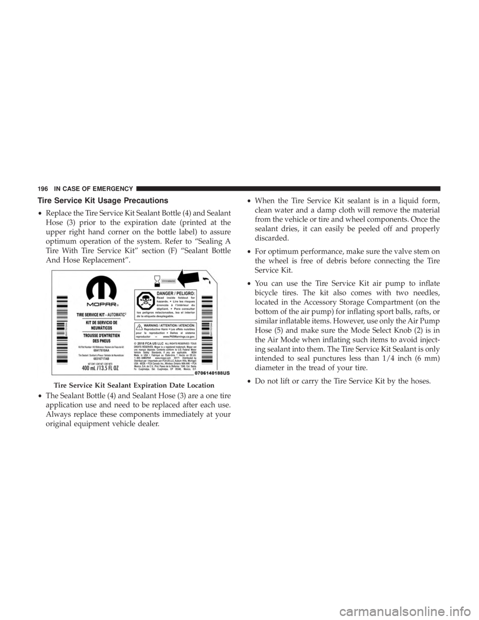
•Replace the Tire Service Kit Sealant Bottle (4) and Sealant
Hose (3) prior to the expiration date (printed at the
upper right hand corner on the bottle label) to assure
optimum operation of the system. Refer to “Sealing A
Tire With Tire Service Kit” section (F) “Sealant Bottle
And Hose Replacement”.
• The Sealant Bottle (4) and Sealant Hose (3) are a one tire
application use and need to be replaced after each use.
Always replace these components immediately at your
original equipment vehicle dealer. •
When the Tire Service Kit sealant is in a liquid form,
clean water and a damp cloth will remove the material
from the vehicle or tire and wheel components. Once the
sealant dries, it can easily be peeled off and properly
discarded.
• For optimum performance, make sure the valve stem on
the wheel is free of debris before connecting the Tire
Service Kit.
• You can use the Tire Service Kit air pump to inflate
bicycle tires. The kit also comes with two needles,
located in the Accessory Storage Compartment (on the
bottom of the air pump) for inflating sport balls, rafts, or
similar inflatable items. However, use only the Air Pump
Hose (5) and make sure the Mode Select Knob (2) is in
the Air Mode when inflating such items to avoid inject-
ing sealant into them. The Tire Service Kit Sealant is only
intended to seal punctures less than 1/4 inch (6 mm)
diameter in the tread of your tire.
• Do not lift or carry the Tire Service Kit by the hoses.
Tire Service Kit Sealant Expiration Date Location
196 IN CASE OF EMERGENCY
Page 199 of 300
WARNING!
•Do not attempt to seal a tire on the side of the vehicle
closest to traffic. Pull far enough off the road to avoid
the danger of being hit when using the Tire Service
Kit.
• Do not use Tire Service Kit or drive the vehicle under
the following circumstances:
– If the puncture in the tire tread is approximately 1/4 inch (6 mm) or larger.
– If the tire has any sidewall damage.
– If the tire has any damage from driving with extremely low tire pressure.
– If the tire has any damage from driving on a flat tire.
– If the wheel has any damage.
– If you are unsure of the condition of the tire or the wheel.
• Keep Tire Service Kit away from open flames or heat
source.
• A loose Tire Service Kit thrown forward in a collision
or hard stop could endanger the occupants of the
vehicle. Always stow the Tire Service Kit in the place
provided. Failure to follow these warnings can result
(Continued)
WARNING! (Continued)
in injuries that are serious or fatal to you, your
passengers, and others around you.
• Take care not to allow the contents of Tire Service Kit
to come in contact with hair, eyes, or clothing. Tire
Service Kit sealant is harmful if inhaled, swallowed,
or absorbed through the skin. It causes skin, eye, and
respiratory irritation. Flush immediately with plenty
of water if there is any contact with eyes or skin.
Change clothing as soon as possible, if there is any
contact with clothing.
• Tire Service Kit Sealant solution contains latex. In
case of an allergic reaction or rash, consult a physi-
cian immediately. Keep Tire Service Kit out of reach
of children. If swallowed, rinse mouth immediately
with plenty of water and drink plenty of water. Do
not induce vomiting! Consult a physician immedi-
ately.
Sealing A Tire With Tire Service Kit
(A) Whenever You Stop To Use Tire Service Kit:
1. Pull over to a safe location and turn on the vehicle’s Hazard Warning flashers.
7
IN CASE OF EMERGENCY 197
Page 200 of 300
2. Verify that the valve stem (on the wheel with thedeflated tire) is in a position that is near to the ground.
This will allow the Tire Service Kit Hoses (3) and (5) to
reach the valve stem and keep the Tire Service Kit flat on
the ground. This will provide the best positioning of the
kit when injecting the sealant into the deflated tire and
running the air pump. Move the vehicle as necessary to
place the valve stem in this position before proceeding.
3. Place the transmission in PARK (auto transmission) or in Gear (manual transmission) and place the ignition in the
OFF position.
4. Apply the parking brake.
(B) Setting Up To Use Tire Service Kit:
1. Push in the Mode Select Knob (2) and turn to the Sealant Mode position.
2. Uncoil the Sealant Hose (3) and then remove the cap from the fitting at the end of the hose.
3. Place the Tire Service Kit flat on the ground next to the deflated tire.
4. Remove the cap from the valve stem and then screw the fitting at the end of the Sealant Hose (3) onto the valve
stem. 5. Uncoil the Power Plug (7) and insert the plug into the
vehicle’s 12 Volt power outlet.
NOTE: Do not remove foreign objects (e.g., screws or
nails) from the tire.
(C) Injecting Tire Service Kit Sealant Into The
Deflated Tire:
• Always start the vehicle before turning ON the Tire
Service Kit.
NOTE: Manual transmission vehicles must have the park-
ing brake engaged and the gear selector in NEUTRAL.
• After pushing the Power Button (1), the sealant (white
fluid) will flow from the Sealant Bottle (4) through the
Sealant Hose (3) and into the tire.
NOTE: Sealant may leak out through the puncture in the
tire.
If the sealant (white fluid) does not flow within0–10
seconds through the Sealant Hose (3):
1. Push the Power Button (1) to turn Off the Tire Service Kit. Disconnect the Sealant Hose (3) from the valve stem.
Make sure the valve stem is free of debris. Reconnect the
Sealant Hose (3) to the valve stem. Check that the Mode
198 IN CASE OF EMERGENCY
Page 201 of 300
Select Knob (2) is in the Sealant Mode position and not
Air Mode. Push the Power Button (1) to turn On the Tire
Service Kit.
2. Connect the Power Plug (7) to a different 12 Volt power outlet in your vehicle or another vehicle, if available.
Make sure the vehicle is running before turning ON the
Tire Service Kit.
3. The Sealant Bottle (4) may be empty due to previous use. Call for assistance.
NOTE: If the Mode Select Knob (2) is on Air Mode and the
pump is operating, air will dispense from the Air Pump
Hose (5) only, not the Sealant Hose (3).
If the sealant (white fluid) does flow through the Sealant
Hose (3):
1. Continue to operate the pump until sealant is no longer flowing through the hose (typically takes 30 - 70 sec-
onds). As the sealant flows through the Sealant Hose (3),
the Pressure Gauge (8) can read as high as 70 psi (4.8
Bar). The Pressure Gauge (8) will decrease quickly from
approximately 70 psi (4.8 Bar) to the actual tire pressure
when the Sealant Bottle (4) is empty. 2. The pump will start to inject air into the tire immedi-
ately after the Sealant Bottle (4) is empty. Continue to
operate the pump and inflate the tire to the pressure
indicated on the tire pressure label on the driver-side
latch pillar (recommended pressure). Check the tire
pressure by looking at the Pressure Gauge (8).
If the tire does not inflate to at least 26 psi (1.8 Bar)
pressure within 15 minutes:
• The tire is too badly damaged. Do not attempt to drive
the vehicle further. Call for assistance.
NOTE: If the tire becomes overinflated, push the Deflation
Button to reduce the tire pressure to the recommended
inflation pressure before continuing.
If the tire inflates to the recommended pressure or is at
least 26 psi (1.8 Bar) pressure within 15 minutes:
1. Push the Power Button (1) to turn off the Tire Service Kit.
2. Remove the Speed Limit sticker from the top of the Sealant Bottle (4) and place the sticker on the instrument
panel.
3. Immediately disconnect the Sealant Hose (3) from the valve stem, reinstall the cap on the fitting at the end of
7
IN CASE OF EMERGENCY 199