2019 DODGE CHARGER SRT check engine
[x] Cancel search: check enginePage 220 of 496
It is recommended for the operator to observe the follow-
ing driving behaviors during the new vehicle break-in
period:
0 to 100 miles (0 to 161 km):
•Do not allow the engine to operate at idle for an
extended period of time.
• Depress the accelerator pedal slowly and not more than
halfway to avoid rapid acceleration.
• Avoid aggressive braking.
• Drive with the engine speed less than 3,500 RPM.
• Maintain vehicle speed below 55 mph (88 km/h) and
observe local speed limits.
100 to 300 miles (161 to 483 km):
• Depress the accelerator pedal slowly and not more than
halfway to avoid rapid acceleration in lower gears (1st to
3rd gears).
• Avoid aggressive braking.
• Drive with the engine speed less than 5,000 RPM.
• Maintain vehicle speed below 70 mph (112 km/h) and
observe local speed limits. 300 to 500 miles (483 to 805 km):
•
Exercise the full engine rpm range, shifting manually at
higher rpms when possible.
• Do not perform sustained operation with the accelerator
pedal at wide open throttle.
• Maintain vehicle speed below 85 mph (136 km/h) and
observe local speed limits.
For the first 1500 miles (2414 km):
• Do not participate in track events, sport driving schools,
or similar activities during the first 1500 miles (2414 km).
NOTE: Check engine oil with every refueling and add if
necessary. Oil and fuel consumption may be higher
through the first oil change interval. Running the engine
with an oil level below the add mark can cause severe
engine damage.
PARKING BRAKE
Before leaving the vehicle, make sure that the parking
brake is fully applied and place the gear selector in the
PARK position.
218 STARTING AND OPERATING
Page 223 of 496
WARNING!(Continued)
•Your vehicle could move and injure you and others if
it is not in PARK. Check by trying to move the
transmission gear selector out of PARK with the
brake pedal released. Make sure the transmission is
in PARK before exiting the vehicle.
• The transmission may not engage PARK if the ve-
hicle is moving. Always bring the vehicle to a
complete stop before shifting to PARK, and verify
that the transmission gear position indicator solidly
indicates PARK (P) without blinking. Ensure that the
vehicle is completely stopped, and the PARK posi-
tion is properly indicated, before exiting the vehicle.
• It is dangerous to shift out of PARK or NEUTRAL if
the engine speed is higher than idle speed. If your
foot is not firmly pressing the brake pedal, the
vehicle could accelerate quickly forward or in re-
verse. You could lose control of the vehicle and hit
someone or something. Only shift into gear when the
engine is idling normally and your foot is firmly
pressing the brake pedal.
• Unintended movement of a vehicle could injure
those in or near the vehicle. As with all vehicles, you
(Continued)
WARNING! (Continued)
should never exit a vehicle while the engine is
running. Before exiting a vehicle, always come to a
complete stop, then apply the parking brake, shift
the transmission into PARK, and turn the ignition
OFF. When the ignition is in the OFF mode, the
transmission is locked in PARK, securing the vehicle
against unwanted movement.
• When exiting the vehicle, always make sure the
ignition is in the OFF mode, remove the key fob from
the vehicle, and lock the vehicle.
• Never leave children alone in a vehicle, or with
access to an unlocked vehicle. Allowing children to
be in a vehicle unattended is dangerous for a number
of reasons. A child or others could be seriously or
fatally injured. Children should be warned not to
touch the parking brake, brake pedal or the trans-
mission gear selector.
• Do not leave the key fob in or near the vehicle (or in
a location accessible to children), and do not leave
the ignition in the ACC or ON/RUN mode. A child
could operate power windows, other controls, or
move the vehicle.
6
STARTING AND OPERATING 221
Page 226 of 496
NOTE:After selecting any gear range, wait a moment to
allow the selected gear to engage before accelerating. This
is especially important when the engine is cold.
PARK (P)
This range supplements the parking brake by locking the
transmission. The engine can be started in this range.
Never attempt to use PARK while the vehicle is in motion.
Apply the parking brake when exiting the vehicle in this
range.
When parking on a level surface, you may shift the
transmission into PARK first, and then apply the parking
brake.
When parking on a hill, apply the parking brake before
shifting the transmission to PARK. As an added precau-
tion, turn the front wheels toward the curb on a downhill
grade and away from the curb on an uphill grade.
When exiting the vehicle, always:
• Apply the parking brake.
• Shift the transmission into PARK.
• Turn the ignition OFF.
• Remove the key fob from the vehicle.WARNING!
•Never use the PARK position as a substitute for the
parking brake. Always apply the parking brake fully
when exiting the vehicle to guard against vehicle
movement and possible injury or damage.
• Your vehicle could move and injure you and others if
it is not in PARK. Check by trying to move the
transmission gear selector out of PARK with the
brake pedal released. Make sure the transmission is
in PARK before exiting the vehicle.
• The transmission may not engage PARK if the ve-
hicle is moving. Always bring the vehicle to a
complete stop before shifting to PARK, and verify
that the transmission gear position indicator solidly
indicates PARK (P) without blinking. Ensure that the
vehicle is completely stopped, and the PARK posi-
tion is properly indicated, before exiting the vehicle.
• It is dangerous to shift out of PARK or NEUTRAL if
the engine speed is higher than idle speed. If your
foot is not firmly pressing the brake pedal, the
vehicle could accelerate quickly forward or in re-
verse. You could lose control of the vehicle and hit
someone or something. Only shift into gear when the
(Continued)
224 STARTING AND OPERATING
Page 233 of 496
NOTE:Launch control is not available within the first 500
miles (804 km) of engine break-in.
Preconditions:
• Launch control should not be used on public roads.
Always check track conditions and the surrounding
area.
• Launch Control should only be used when the engine
and transmission are at operating temperature.
• Launch Control is intended to be used on dry, paved
road surfaces only. Use on slippery or loose surfaces
may cause damage to vehicle components and is not
recommended.
Launch Control is available when the following proce-
dure is followed:
1. Push the LAUNCH button on the center stack switch bank.
NOTE: Pushing the SRT button on the center stack or
pressing Race Options within Drive Modes, then selecting
the Launch Control tab, followed by the soft, Launch
Control button are two other options to access launch
control features. Please refer to “SRT Drive Modes” in
“Multimedia” for further information. 2. Push the “Launch RPM Set-Up” button on the touch-
screen. This screen will allow you to adjust your launch
RPM’s for optimum launch/traction.
3. Push the “Activate Launch Control” button on the touchscreen.
4. Make sure the vehicle is not moving.
5. Make sure the steering wheel is pointing straight.
6. Hold the brake and make sure the vehicle is in “DRIVE” or “AutoStick” position.
7. While holding the brake, rapidly apply and hold the accelerator pedal to wide open throttle. The engine
speed will hold at the RPM that was set in the “Launch
RPM Set-up” screen.
NOTE: Messages will appear in the instrument cluster to
inform the driver if one or more of the above conditions
have not been met.
8. When conditions 4 through 7 have been met, the instru- ment cluster display will read “Launch Ready Release
Brake”.
9. Keep the vehicle pointed straight.
6
STARTING AND OPERATING 231
Page 235 of 496
•It is recommended that each track outing should end
with a minimum of one cool down lap using minimal
braking.
• If equipped with a removable lower front fascia grille, it
is recommended to remove it for track use during
warm/hot weather to improve cooling airflow to critical
powertrain and cooling system components.
• All SRT vehicles are track tested for 24 hours of endur-
ance. However, it is recommended that suspension
system, brake system, prop shaft, and ½ shaft boots
should be checked for wear or damage after every track
event.
• Track usage results in increased operating temperatures
of the engine, transmission, clutch – if equipped, drive-
line and brake system. This may affect noise (NVH)
countermeasures designed into your vehicle. New com-
ponents may need to be installed to return the system to
the original NVH performance.
• For race track usage it is recommended that the axle
fluid be changed every 4 hours of on track time.
• Tire pressure:
• 40psi (276kpa) hot, recommended 32psi (221kpa) front,
30psi (207 kpa) rear cold NOTE:It is recommended that you target 40psi (276kpa) Hot
Tire Pressure at the conclusion of each track session. Starting at
32psi (221kpa) Front and 30psi (207 kpa) Rear Cold and
adjusting based on ambient & track conditions is recom-
mended. Tire pressure can be monitored via the instrument
cluster display and can assist with adjustments.
Track burnishing your brakes:
To avoid “green lining fade” during track use, the brake
pads and rotors must have a thermal burnish for factory
installed components or when new brake friction compo-
nents are installed:
1. Use one track session to burnish brakes by driving at 75% speed. Brake at approximately 0.60-0.80g max with-
out ABS intervention.
2. Lap the track in this manner until you start smelling the brakes. Continue for another half lap at speed, then do
a two lap cool down with minimal brake applies. Make
sure the brakes are not smoking. If they are, do another
cool down lap.
3. Do not continue for more than one full burnishing lap after you start smelling the brakes. Do not get them
smoking heavily. This will get them too hot and affect
their life negatively in future track use.
6
STARTING AND OPERATING 233
Page 237 of 496

WARNING!
Continued operation with reduced power steering as-
sist could pose a safety risk to yourself and others.
Service should be obtained as soon as possible.
CAUTION!
Prolonged operation of the steering system at the end
of the steering wheel travel will increase the steering
fluid temperature and it should be avoided when
possible. Damage to the power steering pump may
occur.
Power Steering Fluid Check
Checking the power steering fluid level at a defined service
interval is not required. The fluid should be checked at
every oil change if a leak is suspected, abnormal noises are
apparent, and/or the system is not functioning as antici-
pated. Coordinate inspection efforts through an authorized
dealer.
WARNING!
Fluid level should be checked on a level surface and
with the engine off to prevent injury from moving
parts and to ensure accurate fluid level reading. Do not
overfill. Use only manufacturer’s recommended power
steering fluid.
CAUTION!
Do not use chemical flushes in your power steering
system as the chemicals can damage your power steer-
ing components. Such damage is not covered by the
New Vehicle Limited Warranty.
If necessary, add fluid to restore to the proper indicated
level. With a clean cloth, wipe any spilled fluid from all
surfaces. Refer to “Fluids And Lubricants” in “Technical
Specifications” for further information.
6
STARTING AND OPERATING 235
Page 295 of 496
General Information
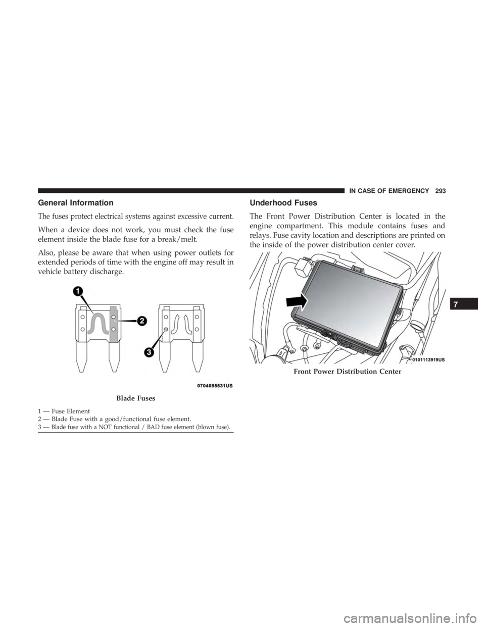
The fuses protect electrical systems against excessive current.
When a device does not work, you must check the fuse
element inside the blade fuse for a break/melt.
Also, please be aware that when using power outlets for
extended periods of time with the engine off may result in
vehicle battery discharge.
Underhood Fuses
The Front Power Distribution Center is located in the
engine compartment. This module contains fuses and
relays. Fuse cavity location and descriptions are printed on
the inside of the power distribution center cover.
Blade Fuses
1 — Fuse Element
2 — Blade Fuse with a good/functional fuse element.
3—
Blade fuse with a NOT functional / BAD fuse element (blown fuse).
Front Power Distribution Center
7
IN CASE OF EMERGENCY 293
Page 308 of 496
3. Place the Tire Service Kit flat on the ground next to thedeflated tire.
4. Remove the cap from the valve stem and then screw the fitting at the end of the Sealant Hose (6) onto the valve
stem.
5. Uncoil the Power Plug (8) and insert the plug into the vehicle’s 12 Volt power outlet.
NOTE: Do not remove foreign objects (e.g., screws or
nails) from the tire.
(C) Injecting Tire Service Kit Sealant Into The
Deflated Tire:
• Always start the engine before turning ON the Tire
Service Kit.
NOTE: Manual transmission vehicles must have the park-
ing brake engaged and the gear selector in NEUTRAL.
• After pushing the Power Button (4), the sealant (white
fluid) will flow from the Sealant Bottle (1) through the
Sealant Hose (6) and into the tire.
NOTE: Sealant may leak out through the puncture in the
tire. If the sealant (white fluid) does not flow within0–10
seconds through the Sealant Hose (6):
1. Push the Power Button (4) to turn Off the Tire Service
Kit. Disconnect the Sealant Hose (6) from the valve stem.
Make sure the valve stem is free of debris. Reconnect the
Sealant Hose (6) to the valve stem. Check that the Mode
Select Knob (5) is in the Sealant Mode position and not
Air Mode. Push the Power Button (4) to turn On the Tire
Service Kit.
2. Connect the Power Plug (8) to a different 12 Volt power outlet in your vehicle or another vehicle, if available.
Make sure the engine is running before turning ON the
Tire Service Kit.
3. The Sealant Bottle (1) may be empty due to previous use. Call for assistance.
NOTE: If the Mode Select Knob (5) is on Air Mode and the
pump is operating, air will dispense from the Air Pump
Hose (7) only, not the Sealant Hose (6).
306 IN CASE OF EMERGENCY