Page 88 of 560
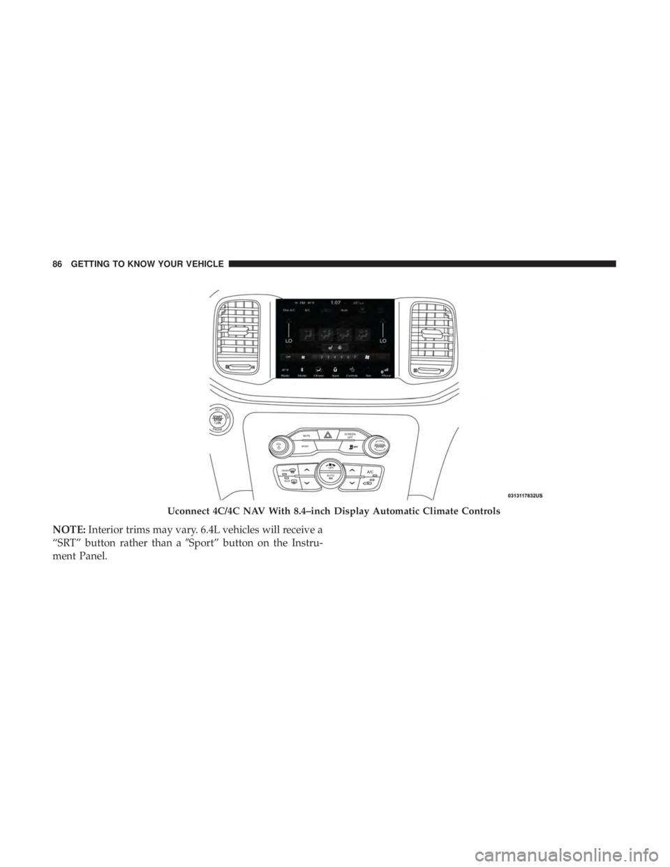
NOTE:Interior trims may vary. 6.4L vehicles will receive a
“SRT” button rather than a �Sport” button on the Instru-
ment Panel.
Uconnect 4C/4C NAV With 8.4–inch Display Automatic Climate Controls
86 GETTING TO KNOW YOUR VEHICLE
Page 94 of 560

Automatic Operation
1. Push the AUTO button on the faceplate, or the AUTObutton on the touchscreen on the Automatic Tempera-
ture Control (ATC) Panel.
2. Next, adju")
Automatic Temperature Control (ATC)
Automatic Operation
1. Push the AUTO button on the faceplate, or the AUTObutton on the touchscreen on the Automatic Tempera-
ture Control (ATC) Panel.
2. Next, adjust the temperature that you would like the system to maintain by adjusting the driver and passen-
ger temperature control buttons. Once the desired tem-
perature is displayed, the system will achieve and
automatically maintain that comfort level.
3. When the system is set up for your comfort level, it is not necessary to change the settings. You will experience
the greatest efficiency by simply allowing the system to
function automatically.
NOTE:
• It is not necessary to move the temperature settings for
cold or hot vehicles. The system automatically adjusts
the temperature, mode, and blower speed to provide
comfort as quickly as possible.
• The temperature can be displayed in U.S. or Metric units
by selecting the US/Metric customer-programmable fea-
ture. Refer to the “Uconnect Settings” in “Multimedia”
for further information. To provide you with maximum comfort in the Automatic
mode during cold start-ups, the blower fan will remain on
low until the engine warms up. The blower will increase in
speed and transition into Auto mode.
Manual Operation Override
This system offers a full complement of manual override
features. The AUTO symbol in the front ATC display will
be turned off when the system is being used in the manual
mode.
Operating Tips
NOTE:
Refer to the chart at the end of this section for
suggested control settings for various weather conditions.
Summer Operation
The engine cooling system must be protected with a
high-quality antifreeze coolant to provide proper corrosion
protection and to protect against engine overheating. OAT
coolant (conforming to MS.90032) is recommended.
Winter Operation
To ensure the best possible heater and defroster perfor-
mance, make sure the engine cooling system is functioning
properly and the proper amount, type, and concentration
of coolant is used. Use of the Air Recirculation mode
92 GETTING TO KNOW YOUR VEHICLE
Page 104 of 560

With the ignition in the ON/RUN position, the trunk open
symbol will display in the instrument cluster indicating
that the trunk is open. The odometer display will reappear
once the trunk is closed.
With the ignition in the OFF position, the trunk open
symbol will display until the trunk is closed.
NOTE:Refer to “Keyless Enter-N-Go — Passive Entry” in
”Doors” in “Getting To Know Your Vehicle” for further
information on trunk operation with the Passive Entry
feature.
Opening From Inside The Vehicle
Interior Power Trunk Release
The trunk can be opened from inside the
vehicle using the power trunk release
button located on the instrument panel
to the left of the steering wheel.
NOTE:The transmission must be in
PARK before the button will operate.
Opening From Outside The Vehicle
To Unlock/Open The Trunk
The trunk may be unlocked/opened using either of the
following methods:
• Key Fob Trunk Release Button
• Passive Entry Button
Key Fob Trunk Release Button Push the power trunk button on the key fob
twice within five seconds to release the trunk.
Passive Entry Button
Push the trunk passive entry button which is located on the
back of the trunk lid. With a valid Passive Entry key fob
within 5 ft (1.5 m) of the trunk, push the passive entry
button to open the trunk.
Power Trunk Release
102 GETTING TO KNOW YOUR VEHICLE
Page 123 of 560

GETTING TO KNOW YOUR INSTRUMENT PANEL
CONTENTS
�INSTRUMENT CLUSTER ..................122
▫ Instrument Cluster Descriptions ............125
� INSTRUMENT CLUSTER DISPLAY ...........126
▫ Location And Controls ...................126
▫ Engine Oil Life Reset ....................128
▫ Performance Shift Indicator (PSI) —
If Equipped .......................... .129
▫ Instrument Cluster Display Selectable Menu
Items .............................. .129
▫ Battery Saver On/Battery Saver Mode
Message — Electrical Load Reduction Actions —
If Equipped ......................... .134�
WARNING LIGHTS AND MESSAGES .........136
▫ Red Warning Lights .....................136
▫ Yellow Warning Lights ...................140
▫ Yellow Indicator Lights ...................145
▫ Green Indicator Lights ...................145
▫ White Indicator Lights ...................146
▫ Blue Indicator Lights ....................146
� ONBOARD DIAGNOSTIC SYSTEM — OBD II . . .147
▫ Onboard Diagnostic System (OBD II)
Cybersecurity ........................ .147
�
EMISSIONS INSPECTION AND MAINTENANCE
PROGRAMS ........................... .148
4
Page 127 of 560
.
2. Instrument Cluster Display •When the appropriate conditions exist, this display")
Instrument Cluster Descriptions
1. Tachometer•Indicates the engine speed in revolutions per minute
(RPM x 1000).
2. Instrument Cluster Display •When the appropriate conditions exist, this display
shows the instrument cluster display messages. Refer
to “Instrument Cluster Display” in “Getting To Know
Your Instrument Panel” for further information.
3. Speedometer •Indicates vehicle speed.
4. Fuel Gauge •The pointer shows the level of fuel in the fuel tank
when the Keyless Push Button Ignition is in the
ON/RUN position.
•
The fuel pump symbol points to the side of the
vehicle where the fuel door is located.
5. Temperature Gauge
•The temperature gauge shows engine coolant tem-
perature. Any reading within the normal range indi-
cates that the engine cooling system is operating
satisfactorily. •
The gauge pointer will likely indicate a higher tempera-
ture when driving in hot weather, up mountain grades,
or when towing a trailer. It should not be allowed to
exceed the upper limits of the normal operating range.
WARNING!
A hot engine cooling system is dangerous. You or
others could be badly burned by steam or boiling
coolant. You may want to call an authorized dealer for
service if your vehicle overheats. If you decide to look
under the hood yourself, see “Servicing And Mainte-
nance.” Follow the warnings under the Cooling System
Pressure Cap paragraph.
CAUTION!
Driving with a hot engine cooling system could dam-
age your vehicle. If the temperature gauge reads “H,”
pull over and stop the vehicle. Idle the vehicle with the
air conditioner turned off until the pointer drops back
into the normal range. If the pointer remains on the
“H,” turn the engine off immediately and call an
authorized dealer for service.
4
GETTING TO KNOW YOUR INSTRUMENT PANEL 125
Page 128 of 560

NOTE:The hard telltales will illuminate for a bulb check
when the ignition is first cycled.
INSTRUMENT CLUSTER DISPLAY
Your vehicle will be equipped with an instrument cluster
display, which offers useful information to the driver. With
the ignition in the STOP/OFF mode, opening/closing of a
door will activate the display for viewing, and display the
total miles, or kilometers, in the odometer. Your instrument
cluster display is designed to display important informa-
tion about your vehicle’s systems and features. Using a
driver interactive display located on the instrument panel,
your instrument cluster display can show you how sys-
tems are working and give you warnings when they are
not. The steering wheel mounted controls allow you to
scroll through the main menus and submenus. You can
access the specific information you want and make selec-
tions and adjustments.
Location And Controls
The instrument cluster display features an interactive
display which is located in the instrument cluster. This system conveniently allows the driver to select a
variety of useful information by pushing the arrow buttons
located on the left side of the steering wheel. The instru-
ment cluster display menu items consist of the following:
•
Speedometer
• Vehicle Info
• Driver Assist — If Equipped
• Fuel Economy
• Trip
Instrument Cluster Display
126 GETTING TO KNOW YOUR INSTRUMENT PANEL
Page 129 of 560
•Audio
• Messages
• Screen Setup
The system allows the driver to select information by
pushing the following buttons mounted on the steering
wheel: Up And Down Arrow Buttons:
Using the
upordown arrows allows you to cycle through
the Main Menu Items.
Changes the Main Screen area and Menu Title area.
Left And Right Arrow Buttons:
Using the leftorright arrow button allows you to cycle
through the submenu items of the Main menu item.
NOTE:
• Holding the up/downorleft/right arrow button will
loop the user through the currently selected menu or
options presented on the screen.
• Main menu and submenus wrap for continuous scroll-
ing.
• Upon returning to a main menu, the last submenu
screen viewed within that main menu will be displayed.
OK Button:
For Digital Speedometer:
• Pushing the OKbutton changes units (mph or km/h).
Instrument Cluster Display Controls
4
GETTING TO KNOW YOUR INSTRUMENT PANEL 127
Page 130 of 560

For Screen Setup:
•OK button allows user to enter menu and submenus.
• Within each submenu layer, the upand down arrows
will allow the user to select the item of interest.
• Pushing the OKbutton makes the selection and a
confirmation screen will appear (returning the user to
the first page of the submenu).
• Pushing the leftarrow button will exit each submenu
layer and return to the main menu.
Engine Oil Life Reset
Oil Change Required
Your vehicle is equipped with an engine oil change indi-
cator system. The “Oil Change Required” message will
display in the instrument cluster display for five seconds
after a single chime has sounded, to indicate the next
scheduled oil change interval. The engine oil change indi-
cator system is duty cycle based, which means the engine
oil change interval may fluctuate, dependent upon your
personal driving style. Unless reset, this message will continue to display each
time you place the ignition in the ON/RUN position. To
turn off the message temporarily, push and release the
OK
or arrow buttons. To reset the oil change indicator system
(after performing the scheduled maintenance), refer to the
following procedure.
Vehicles Equipped With Keyless Enter-N-Go — Ignition
Use the steering wheel instrument cluster display controls
for the following procedure(s):
1. Without pressing the brake pedal, push the ENGINE START/STOP button and place the ignition in the
ON/RUN position (do not start the engine).
2. Push and release the downarrow button to scroll
downward through the main menu to “Vehicle Info.”
3. Push and release the rightarrow button to access the
”Oil Life” screen.
4. Push and hold the OKbutton to reset oil life. If
conditions are met, the gauge and numeric display will
update to show 100%. If conditions are not met a popup
128 GETTING TO KNOW YOUR INSTRUMENT PANEL