2019 DODGE CHARGER warning lights
[x] Cancel search: warning lightsPage 169 of 560

(5 km/h), to objects moving a maximum of approximately
20 mph (32 km/h), such as in parking lot situations.
NOTE:In a parking lot situation, oncoming vehicles can be
obscured by vehicles parked on either side. If the sensors
are blocked by other structures or vehicles, the system will
not be able to alert the driver.
When RCP is on and the vehicle is in REVERSE, the driver
is alerted using both the visual and audible alarms, includ-
ing reducing the radio volume.
WARNING!
Rear Cross Path Detection (RCP) is not a back up aid
system. It is intended to be used to help a driver detect
an oncoming vehicle in a parking lot situation. Drivers
must be careful when backing up, even when using
RCP. Always check carefully behind your vehicle, look
behind you, and be sure to check for pedestrians,
animals, other vehicles, obstructions, and blind spots
before backing up. Failure to do so can result in serious
injury or death.
Modes Of Operation
Three selectable modes of operation are available in the
Uconnect System. Refer to “Uconnect Settings” in “Multi-
media” for further information.
Blind Spot Alert Lights Only
When operating in Blind Spot Alert mode, the BSM system
will provide a visual alert in the appropriate side view
mirror based on a detected object. However, when the
system is operating in Rear Cross Path mode, the system
will respond with both visual and audible alerts when a
detected object is present. Whenever an audible alert is
requested, the radio volume is reduced so that the alert can
be better heard.
Blind Spot Alert Lights/Chime
When operating in Blind Spot Alert Lights/Chime mode,
the BSM system will provide a visual alert in the appro-
priate side view mirror based on a detected object. If the
turn signal is then activated, and it corresponds to an alert
present on that side of the vehicle, an audible chime will
also be sounded. Whenever a turn signal and detected
object are present on the same side at the same time, both
5
SAFETY 167
Page 196 of 560
WARNING!
•Do not drill, cut, or tamper with the knee impact
bolsters in any way.
• Do not mount any accessories to the knee impact
bolsters such as alarm lights, stereos, citizen band
radios, etc.
Supplemental Driver Knee Air Bag
This vehicle is equipped with a Supplemental Driver Knee
Air Bag mounted in the instrument panel below the
steering column. The Supplemental Driver Knee Air Bag
provides enhanced protection during a frontal impact by
working together with the seat belts, pretensioners, and
front air bags.
Supplemental Side Air Bags
Supplemental Seat-Mounted Side Air Bags (SABs)
This vehicle is equipped with Supplemental Seat-Mounted
Side Air Bags (SABs).
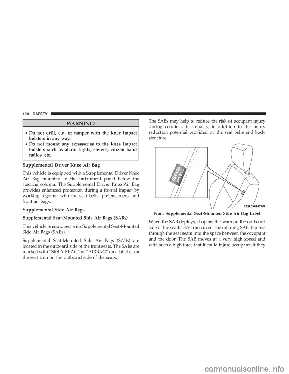
Supplemental Seat-Mounted Side Air Bags (SABs) are
located in the outboard side of the front seats. The SABs are
marked with “SRS AIRBAG” or “AIRBAG” on a label or on
the seat trim on the outboard side of the seats. The SABs may help to reduce the risk of occupant injury
during certain side impacts, in addition to the injury
reduction potential provided by the seat belts and body
structure.
When the SAB deploys, it opens the seam on the outboard
side of the seatback’s trim cover. The inflating SAB deploys
through the seat seam into the space between the occupant
and the door. The SAB moves at a very high speed and
with such a high force that it could injure occupants if theyFront Supplemental Seat-Mounted Side Air Bag Label
194 SAFETY
Page 252 of 560
be taken to the dealer for service. Refer to “Warning Lights
And Messages” in “Getting To Know Your Instrument Panel”
for further information.
NOTE:
•Even if the power steering assistance is no longer
operational, it is still possible to steer the vehicle. Under
these conditions there will be a substantial increase in
steering effort, especially at low speeds and during
parking maneuvers.
• If the condition persists, see your authorized dealer for
service.
If the Steering icon is displayed and the “POWER STEER-
ING SYSTEM OVER TEMP” message is displayed on the
instrument cluster screen, they indicate that extreme steer-
ing maneuvers may have occurred which caused an over
temperature condition in the power steering system. Once
driving conditions are safe, pull over and let the vehicle
idle for a few moments until the icon and message turn off.
SPEED CONTROL — IF EQUIPPED
When engaged, the Speed Control takes over accelerator
operations at speeds greater than 25 mph (40 km/h) or
20 mph (32 km/h), depending on engine size and axle ratio.
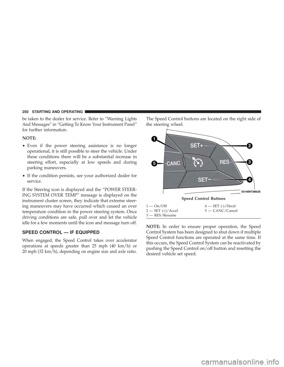
The Speed Control buttons are located on the right side of
the steering wheel.
NOTE: In order to ensure proper operation, the Speed
Control System has been designed to shut down if multiple
Speed Control functions are operated at the same time. If
this occurs, the Speed Control System can be reactivated by
pushing the Speed Control on/off button and resetting the
desired vehicle set speed.
Speed Control Buttons
1 — On/Off 4 — SET (-)/Decel
2 — SET (+)/Accel 5 — CANC/Cancel
3 — RES/Resume
250 STARTING AND OPERATING
Page 265 of 560
Indicator” icon, and the system adjusts vehicle speed
automatically to maintain the distance setting, regardless
of the set speed.
The vehicle will then maintain the set distance until:
•The vehicle ahead accelerates to a speed above the set
speed.
• The vehicle ahead moves out of your lane or view of the
sensor.
• The distance setting is changed.
• The system disengages. (Refer to the information on
ACC Activation).
The maximum braking applied by ACC is limited; how-
ever, the driver can always apply the brakes manually, if
necessary.
NOTE: The brake lights will illuminate whenever the ACC
system applies the brakes.
A Proximity Warning will alert the driver if ACC predicts
that its maximum braking level is not sufficient to maintain
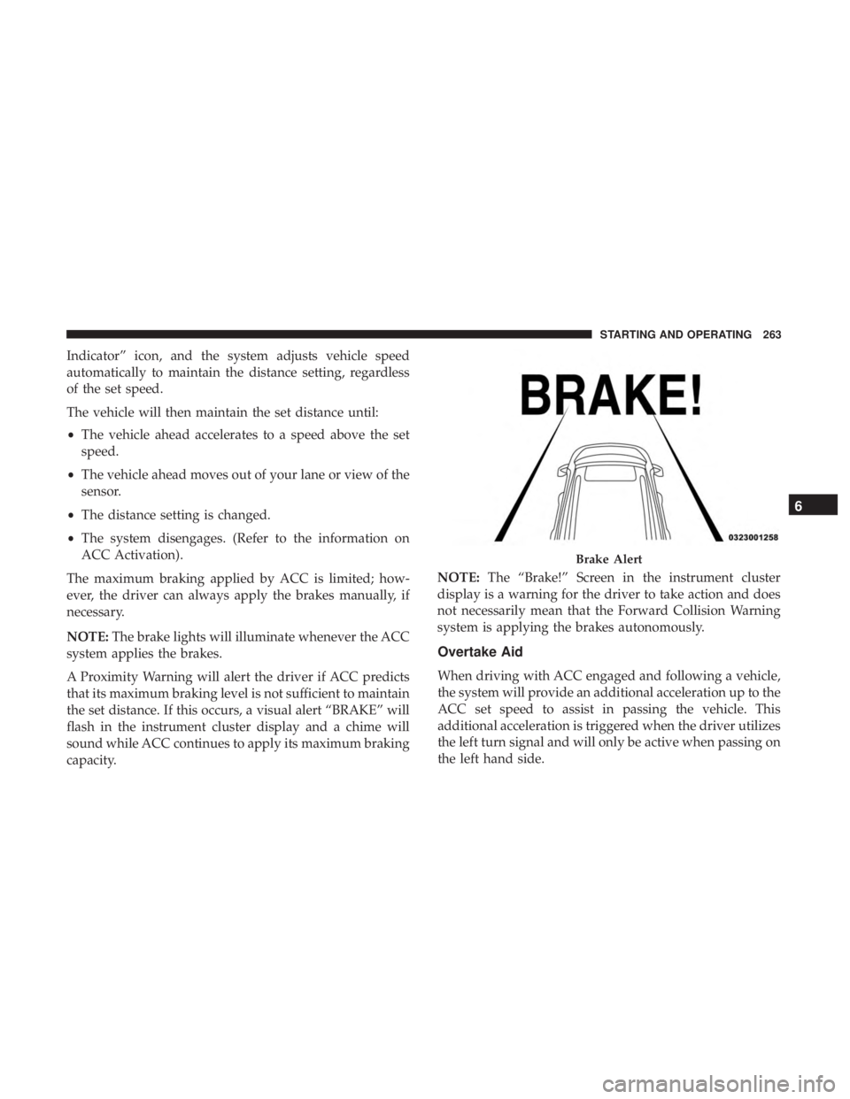
the set distance. If this occurs, a visual alert “BRAKE” will
flash in the instrument cluster display and a chime will
sound while ACC continues to apply its maximum braking
capacity. NOTE:
The “Brake!” Screen in the instrument cluster
display is a warning for the driver to take action and does
not necessarily mean that the Forward Collision Warning
system is applying the brakes autonomously.
Overtake Aid
When driving with ACC engaged and following a vehicle,
the system will provide an additional acceleration up to the
ACC set speed to assist in passing the vehicle. This
additional acceleration is triggered when the driver utilizes
the left turn signal and will only be active when passing on
the left hand side.
Brake Alert
6
STARTING AND OPERATING 263
Page 301 of 560
WARNING!
•Do not connect trailer brakes to your vehicle’s hy-
draulic brake lines. It can overload your brake sys-
tem and cause it to fail. You might not have brakes
when you need them and could have an accident.
• Towing any trailer will increase your stopping dis-
tance. When towing, you should allow for additional
space between your vehicle and the vehicle in front
of you. Failure to do so could result in an accident.
CAUTION!
If the trailer weighs more than 1,000 lbs (453 kg)
loaded, it should have its own brakes and they should
be of adequate capacity. Failure to do this could lead to
accelerated brake lining wear, higher brake pedal
effort, and longer stopping distances.
Towing Requirements — Trailer Lights And Wiring
Whenever you pull a trailer, regardless of the trailer size,
stoplights and turn signals on the trailer are required for
motoring safety.
The Trailer Tow Package may include a four- and seven-pin
wiring harness. Use a factory approved trailer harness and
connector.
NOTE: Do not cut or splice wiring into the vehicle’s wiring
harness.
The electrical connections are all complete to the vehicle
but you must mate the harness to a trailer connector. Refer
to the following illustrations.
NOTE:
• Disconnect trailer wiring connector from the vehicle
before launching a boat (or any other device plugged
into vehicle’s electrical connect) into water.
• Be sure to reconnect after clear from water area.
6
STARTING AND OPERATING 299
Page 316 of 560

Replacing Exterior Bulbs
Front Low/High Beam Headlamp — Models With
Halogen Headlamps
1. Open the hood.
NOTE:Removal of the air cleaner filter housing may be
necessary prior to replacing bulbs in the headlamp assem-
bly on the driver side of the vehicle.
2. Remove the large dust cap from the headlamp housing by turning it counterclockwise.
3. Turn the bulb counterclockwise, and remove.
CAUTION!
Do not touch the new bulb with your fingers. Oil
contamination will severely shorten bulb life. If the
bulb comes in contact with any oily surface, clean the
bulb with rubbing alcohol.
4. Disconnect the bulb from the socket assembly and install the replacement bulb.
5. Reinstall the bulb and socket assembly into the head- lamp assembly, and then turn it clockwise.
6. Reinstall the dust cap.
Front Low/High Beam Headlamp — Models With
High Intensity Discharge Headlamps (HID)
The headlamps are a type of high voltage discharge tube.
High voltage can remain in the circuit even with the
headlamp switch off and the key removed. Because of this,
you should not attempt to service a headlamp bulb
yourself. If a headlamp bulb fails, take your vehicle to an
authorized dealer for service.
WARNING!
A transient high voltage occurs at the bulb sockets of
HID headlamps when the headlamp switch is turned
ON. It may cause serious electrical shock or electrocu-
tion if not serviced properly. See your authorized
dealer for service.
NOTE: On vehicles equipped with HID headlamps, when
the headlamps are turned on, there is a blue hue to the
lights. This diminishes and becomes more white after
approximately 10 seconds, as the system charges.
Front/Rear Side Marker Lamp
The Side Markers use LED lamps that are not serviceable
separately. The Side Markers must be replaced as an
assembly, see your authorized dealer.
314 IN CASE OF EMERGENCY
Page 543 of 560
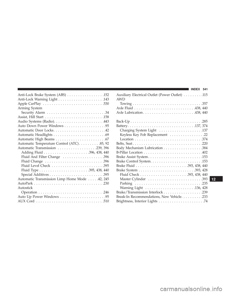
Anti-Lock Brake System (ABS).................152
Anti-Lock Warning Light .....................143
Apple CarPlay ........................... .530
Arming System Security Alarm ...........................34
Assist, Hill Start .......................... .158
Audio Systems (Radio) ...................... .443
Auto Down Power Windows ...................95
Automatic Door Locks ........................42
Automatic Headlights ........................69
Automatic High Beams .......................67
Automatic Temperature Control (ATC) ..........85, 92
Automatic Transmission ..................239, 396
Adding Fluid .....................396, 438, 440
Fluid And Filter Change ...................396
Fluid Change .......................... .396
Fluid Level Check ....................... .395
Fluid Type ...................... .395, 438, 440
Special Additives ........................ .395
Automatic Transmission Limp Home Mode .....42, 245
AutoPark ............................... .230
Autostick Operation ............................. .246
Auto Up Power Windows .....................95
AUXCord .............................. .510Auxiliary Electrical Outlet (Power Outlet)
.........115
AW D Towing ............................... .357
Axle Fluid ........................... .438, 440
Axle Lubrication ....................... .438, 440
Back-Up ................................ .285
Battery .............................. .137, 374
Charging System Light ....................137
Keyless Key Fob Replacement ................22
Location .............................. .374
Belts, Seat ............................... .220
Body Mechanism Lubrication ..................384
B-Pillar Location .......................... .402
Brake Assist System ........................ .153
Brake
Control System ....................... .153
Brake Fluid ....................... .393, 438, 440
Brake System ......................... .393, 428
Fluid Check ..................... .393, 438, 440
Master Cylinder ........................ .393
Parking .............................. .235
Warning Light ...................... .136, 428
Brake/Transmission Interlock ..................239
Break-In Recommendations, New Vehicle ..........233
Brightness, Interior Lights .....................74
12
INDEX 541
Page 546 of 560
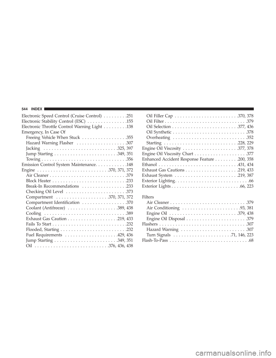
Electronic Speed Control (Cruise Control).........251
Electronic Stability Control (ESC) ...............155
Electronic Throttle Control Warning Light .........138
Emergency, In Case Of Freeing Vehicle When Stuck .................355
Hazard Warning Flasher ...................307
Jacking ........................... .325, 397
Jump Starting ....................... .349, 351
Towing ............................... .356
Emission Control System Maintenance ............148
Engine .......................... .370, 371, 372
Air Cleaner ............................ .379
Block Heater ........................... .233
Break-In Recommendations .................233
Checking Oil Level ...................... .373
Compartment ....................370, 371, 372
Compartment Identification .................370
Coolant (Antifreeze) ...................389, 438
Cooling .............................. .389
Exhaust Gas Caution ...................219, 433
Fails To Start ........................... .232
Flooded, Starting ........................ .232
Fuel Requirements ....................429, 436
Jump Starting ....................... .349, 351
Oil ........................... .376, 436, 438Oil Filler Cap
....................... .370, 378
Oil Filter .............................. .379
Oil Selection ........................ .377, 436
Oil Synthetic ........................... .378
Overheating ........................... .352
Starting ........................... .228, 229
Engine Oil Viscosity .....................377, 378
Engine Oil Viscosity Chart ....................377
Enhanced Accident Response Feature .........200, 358
Ethanol ............................. .431, 434
Exhaust
Gas Cautions ....................219, 433
Exhaust System ....................... .219, 387
Exterior Lighting ............................66
Exterior Lights ......................... .66, 223
Filters Air Cleaner ............................ .379
Air Conditioning ..................... .93, 381
Engine Oil ......................... .379, 438
Engine Oil Disposal ...................... .379
Flashers ................................ .307
Hazard Warning ........................ .307
Turn Signals ..................... .71, 146, 223
Flash-To-Pass ..............................68
544 INDEX