Page 73 of 560

NOTE:The fog lights will operate with the low beam
headlights or parking lights on. However, selecting the
high beam headlights will turn off the fog lights.
Turn Signals
Move the multifunction lever up or down and the arrows
on each side of the instrument cluster display flash to show
proper operation of the front and rear turn signal lights.
NOTE:
• If either light remains on and does not flash, or there is
a very fast flash rate, check for a defective outside light
bulb. If an indicator fails to light when the lever is
moved, it would suggest that the indicator bulb is
defective.
• A “Turn Signal On” message will appear in the instru-
ment cluster display and a continuous chime will sound
if the vehicle is driven more than 1 mile (1.6 km) with
either turn signal on.
Lane Change Assist — If Equipped
Tap the multifunction lever up or down once, without
moving beyond the detent, and the turn signal (right or
left) will flash three times then automatically turn off.
INTERIOR LIGHTS
The interior lights come on when a door is opened.
To protect the battery, the interior lights will turn off
automatically ten minutes after the ignition is moved to the
OFF position. This will occur if the interior lights were
switched on manually or are on because a door is open.
The Battery Protection also includes the glove compart-
ment light and the trunk light. To restore interior light
operation after automatic battery protection is enabled
(lights off), either place the ignition in the ON/RUN
position or cycle the light switch.
3
GETTING TO KNOW YOUR VEHICLE 71
Page 107 of 560

GARAGE DOOR OPENER — IF EQUIPPED
HomeLink replaces up to three hand-held transmitters that
operate devices such as garage door openers, motorized
gates, lighting or home security systems. The HomeLink
unit is powered by your vehicle’s battery.
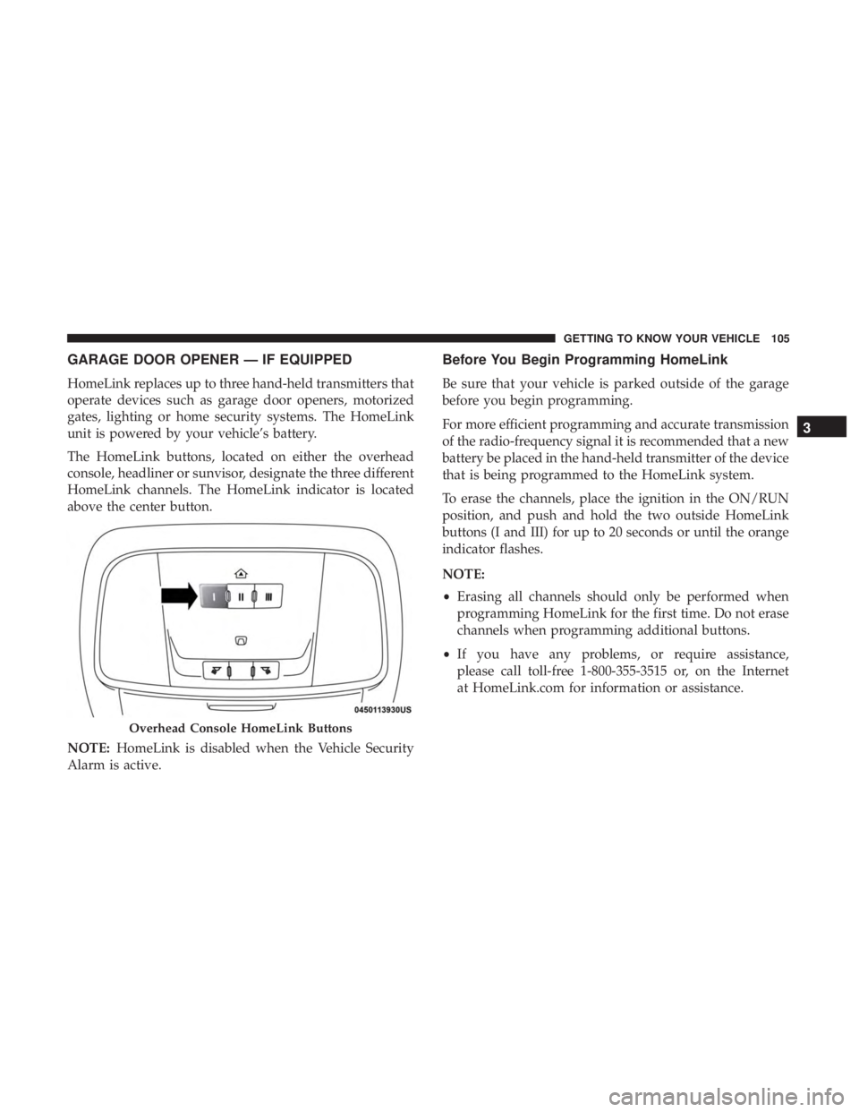
The HomeLink buttons, located on either the overhead
console, headliner or sunvisor, designate the three different
HomeLink channels. The HomeLink indicator is located
above the center button.
NOTE:HomeLink is disabled when the Vehicle Security
Alarm is active.
Before You Begin Programming HomeLink
Be sure that your vehicle is parked outside of the garage
before you begin programming.
For more efficient programming and accurate transmission
of the radio-frequency signal it is recommended that a new
battery be placed in the hand-held transmitter of the device
that is being programmed to the HomeLink system.
To erase the channels, place the ignition in the ON/RUN
position, and push and hold the two outside HomeLink
buttons (I and III) for up to 20 seconds or until the orange
indicator flashes.
NOTE:
• Erasing all channels should only be performed when
programming HomeLink for the first time. Do not erase
channels when programming additional buttons.
• If you have any problems, or require assistance,
please call toll-free 1-800-355-3515 or, on the Internet
at HomeLink.com for information or assistance.
Overhead Console HomeLink Buttons
3
GETTING TO KNOW YOUR VEHICLE 105
Page 112 of 560

Security
It is advised to erase all channels before you sell or turn in
your vehicle.
To do this, push and hold the two outside buttons for
20 seconds until the orange indicator flashes. Note that all
channels will be erased. Individual channels cannot be
erased.
The HomeLink Universal Transceiver is disabled when the
Vehicle Security Alarm is active.
Troubleshooting Tips
If you are having trouble programming HomeLink, here
are some of the most common solutions:
•Replace the battery in the Garage Door Opener hand-
held transmitter.
• Push the LEARN button on the Garage Door Opener to
complete the training for a Rolling Code.
• Did you unplug the device for programming and re-
member to plug it back in? If you have any problems, or require assistance, please
call toll-free 1-800-355-3515 or, on the Internet at
HomeLink.com for information or assistance.
WARNING!
•
Vehicle exhaust contains carbon monoxide, a danger-
ous gas. Do not run your vehicle in the garage while
programming the transceiver. Exhaust gas can cause
serious injury or death.
• Your motorized door or gate will open and close
while you are programming the universal trans-
ceiver. Do not program the transceiver if people, pets
or other objects are in the path of the door or gate.
Only use this transceiver with a garage door opener
that has a “stop and reverse” feature as required by
Federal safety standards. This includes most garage
door opener models manufactured after 1982. Do not
use a garage door opener without these safety fea-
tures. Call toll-free 1-800-355-3515 or, on the Internet
at HomeLink.com for safety information or assis-
tance.
110 GETTING TO KNOW YOUR VEHICLE
Page 117 of 560

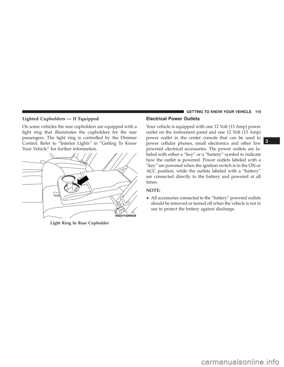
Lighted Cupholders — If Equipped
On some vehicles the rear cupholders are equipped with a
light ring that illuminates the cupholders for the rear
passengers. The light ring is controlled by the Dimmer
Control. Refer to “Interior Lights” in “Getting To Know
Your Vehicle” for further information.
Electrical Power Outlets
Your vehicle is equipped with one 12 Volt (13 Amp) power
outlet on the instrument panel and one 12 Volt (13 Amp)
power outlet in the center console that can be used to
power cellular phones, small electronics and other low
powered electrical accessories. The power outlets are la-
beled with either a “key” or a “battery” symbol to indicate
how the outlet is powered. Power outlets labeled with a
“key” are powered when the ignition switch is in the ON or
ACC position, while the outlets labeled with a “battery”
are connected directly to the battery and powered at all
times.
NOTE:
•
All accessories connected to the “battery” powered outlets
should be removed or turned off when the vehicle is not in
use to protect the battery against discharge.
Light Ring In Rear Cupholder
3
GETTING TO KNOW YOUR VEHICLE 115
Page 119 of 560

NOTE:The instrument panel power outlet and dual rear
console USB ports can be changed to “battery” powered all
the time by moving the #12 20 Amp fuse from “IGN” to
“B+”. Refer to “Fuses” in “In Case Of Emergency” for
further information.
WARNING!
To avoid serious injury or death:
• Only devices designed for use in this type of outlet
should be inserted into any 12 Volt outlet.
• Do not touch with wet hands.
• Close the lid when not in use and while driving the
vehicle.
• If this outlet is mishandled, it may cause an electric
shock and failure.
CAUTION!
• Many accessories that can be plugged in draw power
from the vehicle’s battery even when not in use (i.e.,
cellular phones, etc.). Eventually, if plugged in long
enough, the vehicle’s battery will discharge suffi-
ciently to degrade battery life and/or prevent the
engine from starting.
• Accessories that draw higher power (i.e., coolers,
vacuum cleaners, lights, etc.) will degrade the battery
even more quickly. Only use these intermittently and
with greater caution.
(Continued)
Power Outlet Fuse Locations
1 — #12 Fuse 20 Amp Yellow Instrument Panel Power Outlet/Dual
USB Charge Only Ports
2 — #38 Fuse 20 Amp Yellow Center Console Power Outlet/Media
Hub
3
GETTING TO KNOW YOUR VEHICLE 117
Page 120 of 560

CAUTION!(Continued)
•After the use of high power draw accessories or long
periods of the vehicle not being started (with acces-
sories still plugged in), the vehicle must be driven a
sufficient length of time to allow the alternator to
recharge the vehicle’s battery.
• Power outlets are designed for accessory plugs only.
Do not hang any type of accessory or accessory
bracket from the plug. Improper use of the power
outlet can cause damage.
Wireless Charging Pad — If Equipped
Your vehicle may be equipped with an Open Dots compat-
ible wire-free phone charging surface located in the center
console. The wireless charger features continuous wireless
charging during vehicle operation and allows for uninter-
rupted Bluetooth streaming to properly equipped vehicle
audio systems. In order to enjoy the convenience of Open Dots wire-free
charging, you must obtain an aftermarket wireless-enabled
case and then install the case on your phone. Set the phone
on the wireless charging pad face up. The charging indi-
cator on your phone will light up indicating that your
phone is charging.
NOTE:
The charging pad is safe to the touch. However, if
metallic items are placed on the charging surface while in
use, the device will turn off. Clean all spills immediately
and allow to dry before using.
Wireless Charging Pad
118 GETTING TO KNOW YOUR VEHICLE
Page 123 of 560

GETTING TO KNOW YOUR INSTRUMENT PANEL
CONTENTS
�INSTRUMENT CLUSTER ..................122
▫ Instrument Cluster Descriptions ............125
� INSTRUMENT CLUSTER DISPLAY ...........126
▫ Location And Controls ...................126
▫ Engine Oil Life Reset ....................128
▫ Performance Shift Indicator (PSI) —
If Equipped .......................... .129
▫ Instrument Cluster Display Selectable Menu
Items .............................. .129
▫ Battery Saver On/Battery Saver Mode
Message — Electrical Load Reduction Actions —
If Equipped ......................... .134�
WARNING LIGHTS AND MESSAGES .........136
▫ Red Warning Lights .....................136
▫ Yellow Warning Lights ...................140
▫ Yellow Indicator Lights ...................145
▫ Green Indicator Lights ...................145
▫ White Indicator Lights ...................146
▫ Blue Indicator Lights ....................146
� ONBOARD DIAGNOSTIC SYSTEM — OBD II . . .147
▫ Onboard Diagnostic System (OBD II)
Cybersecurity ........................ .147
�
EMISSIONS INSPECTION AND MAINTENANCE
PROGRAMS ........................... .148
4
Page 132 of 560

Vehicle Info
Push and release theupordown arrow button until the
“Vehicle Info” menu is displayed in the instrument cluster
display. Push and release the rightorleft arrow button to
scroll through the submenus items of “Vehicle Info.” Fol-
low the directional prompts to access or reset any of the
following “Vehicle Info” submenu items:
• Tire Pressure Monitor
• Coolant Temp
• Trans Temp
• Oil Temp
• Oil Pressure
• Oil Life
• Battery Voltage
• AWD Status — If Equipped
Driver Assist — If Equipped
The Driver Assist menu displays the status of the ACC and
LaneSense systems. Push and release the
upordown arrow button until the
Driver Assist menu is displayed in the instrument cluster
display.
Adaptive Cruise Control (ACC) Feature
The instrument cluster displays the current ACC system
settings. The information displayed depends on ACC sys-
tem status.
Push the Adaptive Cruise Control (ACC) on/off button
(located on the steering wheel) until one of the following
displays in the instrument cluster display:
Adaptive Cruise Control Off
When ACC is deactivated, the display will read “Adaptive
Cruise Control Off.”
Adaptive Cruise Control Ready
When ACC is activated but the vehicle speed setting has
not been selected, the display will read “Adaptive Cruise
Control Ready.”
130 GETTING TO KNOW YOUR INSTRUMENT PANEL