Page 334 of 560

NOTE:•For vehicles that are equipped, do not attempt to
install a center cap or wheel cover on the compact
spare.
•
Refer to “Tires—General Information” in “Servicing
And Maintenance” for additional warnings, cautions,
and information about the spare tire, its use, and opera-
tion.
8. Install the lug nuts with the cone shaped end of the lug nut toward the wheel. Lightly tighten the lug nuts.
WARNING!
To avoid the risk of forcing the vehicle off the jack, do
not tighten the wheel nuts fully until the vehicle has
been lowered. Failure to follow this warning may
result in serious injury.
9. Lower the vehicle to the ground by turning the jack handle counterclockwise. 10. Finish tightening the lug nuts. Push down on the
wrench while at the end of the handle for increased
leverage. Tighten the lug nuts in a star pattern until
each nut has been tightened twice. Refer to “Torque
Specifications” in “Technical Specifications” for proper
lug nut torque.
11. Stow the wheel chocks, jack, tools and flat tire. Make sure the base of the jack faces the front of the vehicle
before tightening down the fastener.
WARNING!
A loose tire or jack thrown forward in a collision or
hard stop could endanger the occupants of the vehicle.
Always stow the jack parts and the spare tire in the
places provided. Have the deflated (flat) tire repaired
or replaced immediately.
Road Tire Installation
1. Mount the road tire on the axle.
2.
Install the remaining lug nuts with the cone shaped end of
the nut toward the wheel. Lightly tighten the lug nuts.
332 IN CASE OF EMERGENCY
Page 335 of 560

WARNING!
To avoid the risk of forcing the vehicle off the jack, do
not tighten the wheel nuts fully until the vehicle has
been lowered. Failure to follow this warning may
result in serious injury.
3. Lower the vehicle to the ground by turning the jack handle counterclockwise.
4. Refer to “Torque Specifications” in “Technical Specifica- tions” for proper lug nut torque.
5. After 25 miles (40 km), check the lug nut torque with a torque wrench to ensure that all lug nuts are properly
seated against the wheel.
TIRE SERVICE KIT — IF EQUIPPED
Small punctures up to 1/4 inch (6 mm) in the tire tread can
be sealed with Tire Service Kit. Foreign objects (e.g., screws
or nails) should not be removed from the tire. Tire Service
Kit can be used in outside temperatures down to approxi-
mately -4°F (-20°C). This kit will provide a temporary tire seal, allowing you to
drive your vehicle up to 100 miles (160 km) with a
maximum speed of 50 mph (80 km/h).
Tire Service Kit Storage
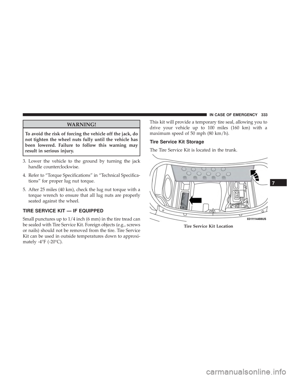
The Tire Service Kit is located in the trunk.
Tire Service Kit Location
7
IN CASE OF EMERGENCY 333
Page 343 of 560

5. Position the new Sealant Bottle (1) in the housing so thatthe Sealant Hose (6) aligns with the hose slot in the front
of the housing. Push the bottle into the housing. An
audible click will be heard indicating the bottle is locked
into place.
6. Verify that the cap is installed on the fitting at the end of the Sealant Hose (6) and return the hose to its storage
area (located on the bottom of the air pump).
7. Return the Tire Service Kit to its storage location in the vehicle.
TIRE SERVICE KIT — IF EQUIPPED
Small punctures up to 1/4 inch (6 mm) in the tire tread can
be sealed with Tire Service Kit. Foreign objects (e.g., screws
or nails) should not be removed from the tire. Tire Service
Kit can be used in outside temperatures down to approxi-
mately -4°F (-20°C).
This kit will provide a temporary tire seal, allowing you to
drive your vehicle up to 100 miles (160 km) with a
maximum speed of 50 mph (80 km/h).
Tire Service Kit Storage
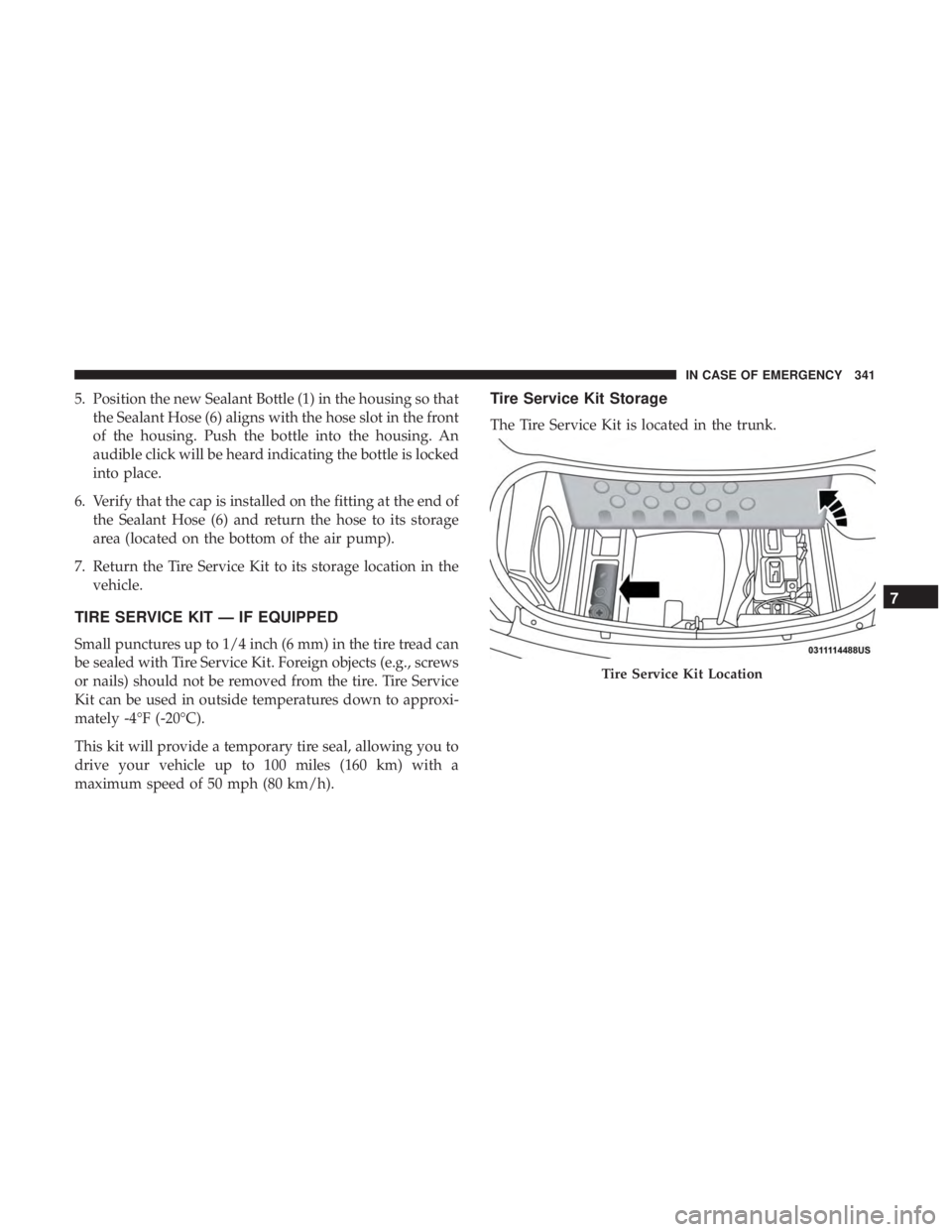
The Tire Service Kit is located in the trunk.
Tire Service Kit Location
7
IN CASE OF EMERGENCY 341
Page 351 of 560

5. Position the new Sealant Bottle (4) in the housing so thatthe Sealant Hose (3) aligns with the hose slot in the front
of the housing. Push and hold the Sealant Bottle release
button, then push the bottle into the housing by holding
the button. An audible click will be heard indicating the
bottle is locked into place. Release the button.
6. Verify that the cap is installed on the fitting at the end of the Sealant Hose (3) and return the hose to its storage
area (located on top of the housing).
7. Return the Tire Service Kit to its storage location in the vehicle.
JUMP STARTING
If your vehicle has a discharged battery, it can be jump
started using a set of jumper cables and a battery in another
vehicle, or by using a portable battery booster pack. Jump
starting can be dangerous if done improperly, so please
follow the procedures in this section carefully.
WARNING!
Do not attempt jump starting if the battery is frozen.
It could rupture or explode and cause personal injury.
CAUTION!
Do not use a portable battery booster pack or any other
booster source with a system voltage greater than 12
Volts or damage to the battery, starter motor, alternator
or electrical system may occur.
NOTE: When using a portable battery booster pack, follow
the manufacturer’s operating instructions and precautions.
Preparations For Jump Start
The battery is stored under an access cover in the trunk.
Remote battery posts are located on the right side of the
engine compartment for jump starting.
NOTE: The remote battery posts are viewed by standing
on the right side of the vehicle looking over the fender.
7
IN CASE OF EMERGENCY 349
Page 356 of 560

5. Press and maintain firm pressure on the brake pedal.
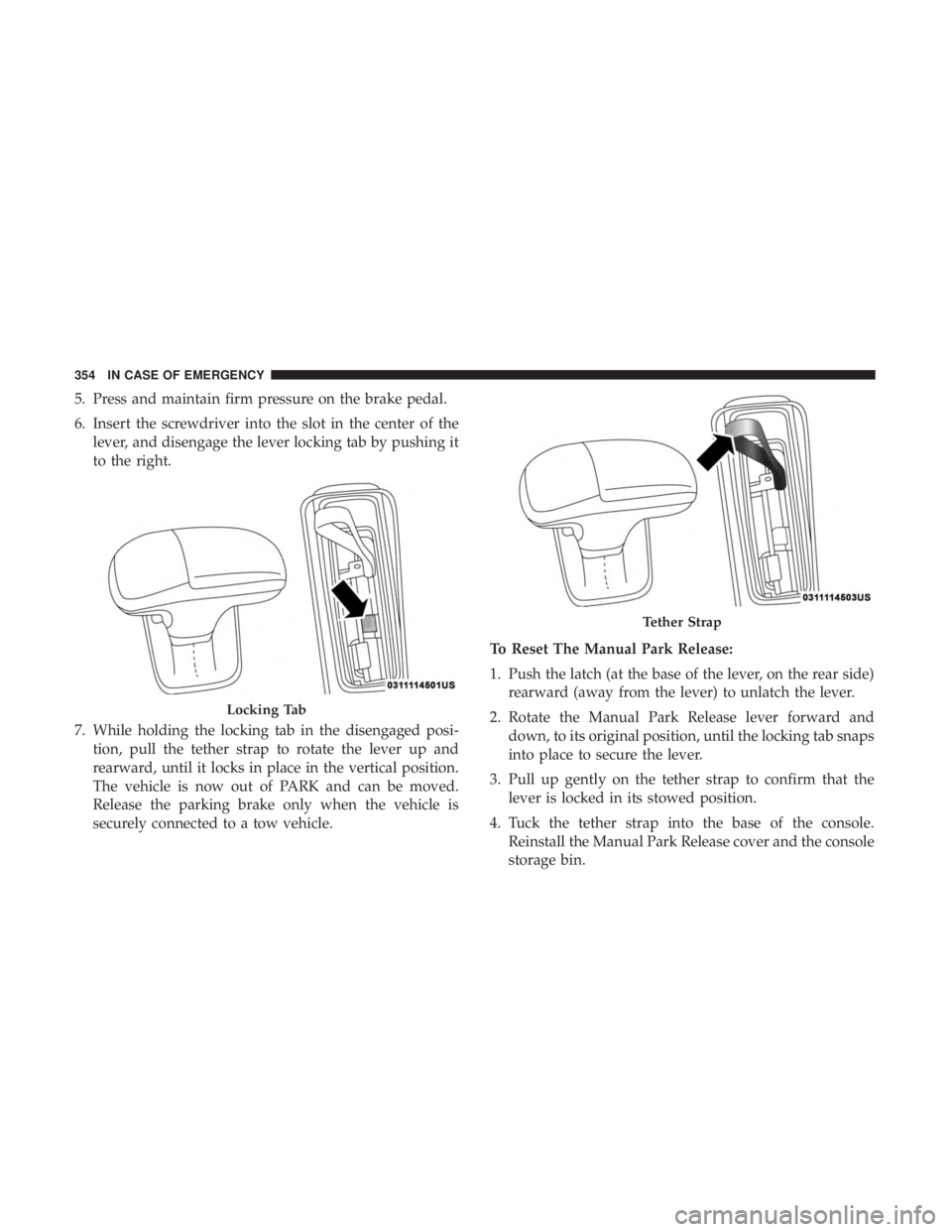
6. Insert the screwdriver into the slot in the center of thelever, and disengage the lever locking tab by pushing it
to the right.
7. While holding the locking tab in the disengaged posi- tion, pull the tether strap to rotate the lever up and
rearward, until it locks in place in the vertical position.
The vehicle is now out of PARK and can be moved.
Release the parking brake only when the vehicle is
securely connected to a tow vehicle. To Reset The Manual Park Release:
1. Push the latch (at the base of the lever, on the rear side)
rearward (away from the lever) to unlatch the lever.
2. Rotate the Manual Park Release lever forward and down, to its original position, until the locking tab snaps
into place to secure the lever.
3. Pull up gently on the tether strap to confirm that the lever is locked in its stowed position.
4. Tuck the tether strap into the base of the console. Reinstall the Manual Park Release cover and the console
storage bin.
Locking Tab
Tether Strap
354 IN CASE OF EMERGENCY
Page 357 of 560

FREEING A STUCK VEHICLE
If your vehicle becomes stuck in mud, sand, or snow, it can
often be moved using a rocking motion. Turn the steering
wheel right and left to clear the area around the front
wheels. Push and hold the lock button on the gear selector.
Then, shift back and forth between DRIVE and REVERSE
while gently pressing the accelerator. Use the least amount
of accelerator pedal pressure that will maintain the rocking
motion, without spinning the wheels or racing the engine.
NOTE:
•Shifts between DRIVE and REVERSE can only be
achieved at wheel speeds of 5 mph (8 km/h) or less.
Whenever the transmission remains in NEUTRAL for
more than two seconds, you must press the brake pedal
to engage DRIVE or REVERSE.
• Push the �ESC Off� switch, to place the Electronic
Stability Control (ESC) system in �Partial Off�mode,
before rocking the vehicle. Refer to “Electronic Brake
Control System” in “Safety” for further information.
Once the vehicle has been freed, push the �ESC Off�
switch again to restore �ESC On�mode.
WARNING!
Fast spinning tires can be dangerous. Forces generated
by excessive wheel speeds may cause damage, or even
failure, of the axle and tires. A tire could explode and
injure someone. Do not spin your vehicle’s wheels
faster than 30 mph (48 km/h) or for longer than 30
seconds continuously without stopping when you are
stuck and do not let anyone near a spinning wheel, no
matter what the speed.
CAUTION!
•Racing the engine or spinning the wheels may lead
to transmission overheating and failure. Allow the
engine to idle with the transmission in NEUTRAL
for at least one minute after every five rocking-
motion cycles. This will minimize overheating and
reduce the risk of transmission failure during pro-
longed efforts to free a stuck vehicle.
(Continued)
7
IN CASE OF EMERGENCY 355
Page 386 of 560

•Belt broken (note: identify and correct problem before
new belt is installed)
• Noise (objectionable squeal, squeak, or rumble is heard
or felt while drive belt is in operation)
Some conditions can be caused by a faulty component such
as a belt pulley. Belt pulleys should be carefully inspected
for damage and proper alignment.
Belt replacement on some models requires the use of
special tools, we recommend having your vehicle serviced
at an authorized dealer.
Body Lubrication
Locks and all body pivot points, including such items as
seat tracks, door hinge pivot points and rollers, liftgate,
tailgate, decklid, sliding doors and hood hinges, should be
lubricated periodically with a lithium based grease, such as
Mopar Spray White Lube to assure quiet, easy operation
and to protect against rust and wear. Prior to the applica-
tion of any lubricant, the parts concerned should be wiped
clean to remove dust and grit; after lubricating excess oil
and grease should be removed. Particular attention should
also be given to hood latching components to ensure proper function. When performing other underhood ser-
vices, the hood latch, release mechanism and safety catch
should be cleaned and lubricated.
The external lock cylinders should be lubricated twice a
year, preferably in the Fall and Spring. Apply a small
amount of a high quality lubricant, such as Mopar Lock
Cylinder Lubricant directly into the lock cylinder.
Windshield Wiper Blades
Clean the rubber edges of the wiper blades and the
windshield periodically with a sponge or soft cloth and a
mild nonabrasive cleaner. This will remove accumulations
of salt or road film.
Operation of the wipers on dry glass for long periods may
cause deterioration of the wiper blades. Always use washer
fluid when using the wipers to remove salt or dirt from a
dry windshield.
Avoid using the wiper blades to remove frost or ice from
the windshield. Keep the blade rubber out of contact with
petroleum products such as engine oil, gasoline, etc.
384 SERVICING AND MAINTENANCE
Page 387 of 560
NOTE:Life expectancy of wiper blades varies depending
on geographical area and frequency of use. Poor perfor-
mance of blades may be present with chattering, marks,
water lines or wet spots. If any of these conditions are
present, clean the wiper blades or replace as necessary.
Wiper Blade Removal/Installation
CAUTION!
Do not allow the wiper arm to spring back against the
glass without the wiper blade in place or the glass may
be damaged.
1. Lift the wiper arm to raise the wiper blade off of the glass, until the wiper arm is in the full up position.
Windshield Wiper Arm
1—Wiper
2 — Locking Tab
3—WiperArm
8
SERVICING AND MAINTENANCE 385