Page 147 of 500
. The zone
length starts at the outside rear view mirror and extends
approximately 10 ft (3 m) beyo")
The BSM detection zone covers approximately one lane
width on both sides of the vehicle 12 ft (3.8 m). The zone
length starts at the outside rear view mirror and extends
approximately 10 ft (3 m) beyond the rear bumper of the
vehicle. The BSM system monitors the detection zones on
both sides of the vehicle when the vehicle speed reaches
approximately 6 mph (10 km/h) or higher and will alert
the driver of vehicles in these areas.
NOTE:
•The BSM system does NOT alert the driver about
rapidly approaching vehicles that are outside the detec-
tion zones.
• The BSM system detection zone DOES NOT change if
your vehicle is towing a trailer. Therefore, visually verify
the adjacent lane is clear for both your vehicle and trailer
before making a lane change. If the trailer or other object
(i.e., bicycle, sports equipment) extends beyond the side
of your vehicle, this may result in the BSM warning light
remaining illuminated the entire time the vehicle is in a
forward gear.
• The BSM system may experience drop outs (blinking on
and off) of the side mirror Warning Indicator lamps
when a motorcycle or any small object remains at the
side of the vehicle for extended periods of time (more
than a couple of seconds). The area on the rear fascia where the radar sensors are
located must remain free of snow, ice and dirt/road
contamination so that the BSM system can function prop-
erly. Do not block the area of the rear fascia where the radar
sensors are located with foreign objects (bumper stickers,
bicycle racks, etc.).
The BSM system notifies the driver of objects in the
detection zones by illuminating the BSM warning light
located in the outside mirrors in addition to sounding an
audible (chime) alert and reducing the radio volume. Refer
to “Modes Of Operation” for further information.
Sensor Location
5
SAFETY 145
Page 275 of 500
, the rear camera mode is exited and the
last touchscreen appears again.
When enabled, active guide lines are overlaid on the i")
When the vehicle is shifted out of REVERSE (with Camera
Delay turned off), the rear camera mode is exited and the
last touchscreen appears again.
When enabled, active guide lines are overlaid on the image
to illustrate the width of the vehicle and its projected
backup path based on the steering wheel position. The
active guide lines will show separate zones that will help
indicate the distance to the rear of the vehicle.If the vehicle speed remains below 8 mph (13 km/h), the
rear view camera image will continue to be displayed until
the transmission is shifted into PARK, the vehicle’s ignition
is cycled to the OFF position, or the image defeat [X] button
is pressed.
Different colored zones indicate the distance to the rear of
the vehicle.
The following table shows the approximate distances for
each zone:
Zone
Distance To The Rear Of The Vehicle
Red 0 - 1 ft (0 - 30 cm)
Yellow 1 ft - 6.5 ft (30 cm - 2 m)
Green 6.5 ft or greater (2 m or greater)
WARNING!
Drivers must be careful when backing up even when
using the ParkView Rear Back Up Camera. Always
check carefully behind your vehicle, and be sure to
(Continued)
WARNING!(Continued)
check for pedestrians, animals, other vehicles, obstruc-
tions, or blind spots before backing up. You are re-
sponsible for the safety of your surroundings and must
continue to pay attention while backing up. Failure to
do so can result in serious injury or death.
6
STARTING AND OPERATING 273
Page 363 of 500
 — Metric tire sizing is based on U.S.
design standards. P-Metric tires have the letter “P”
molded into the sidewall preceding the size designation.
Example: P215/65R15 95H")
NOTE:
•P (Passenger) — Metric tire sizing is based on U.S.
design standards. P-Metric tires have the letter “P”
molded into the sidewall preceding the size designation.
Example: P215/65R15 95H.
• European — Metric tire sizing is based on European
design standards. Tires designed to this standard have
the tire size molded into the sidewall beginning with the
section width. The letter �P�is absent from this tire size
designation. Example: 215/65R15 96H.
• LT (Light Truck) — Metric tire sizing is based on U.S.
design standards. The size designation for LT-Metric
tires is the same as for P-Metric tires except for the letters
“LT” that are molded into the sidewall preceding the
size designation. Example: LT235/85R16. •
Temporary spare tires are designed for temporary emer-
gency use only. Temporary high pressure compact spare
tires have the letter “T” or “S” molded into the sidewall
preceding the size designation. Example: T145/80D18
103M.
• High flotation tire sizing is based on U.S. design stan-
dards and it begins with the tire diameter molded into
the sidewall. Example: 31x10.5 R15 LT.
8
SERVICING AND MAINTENANCE 361
Page 364 of 500
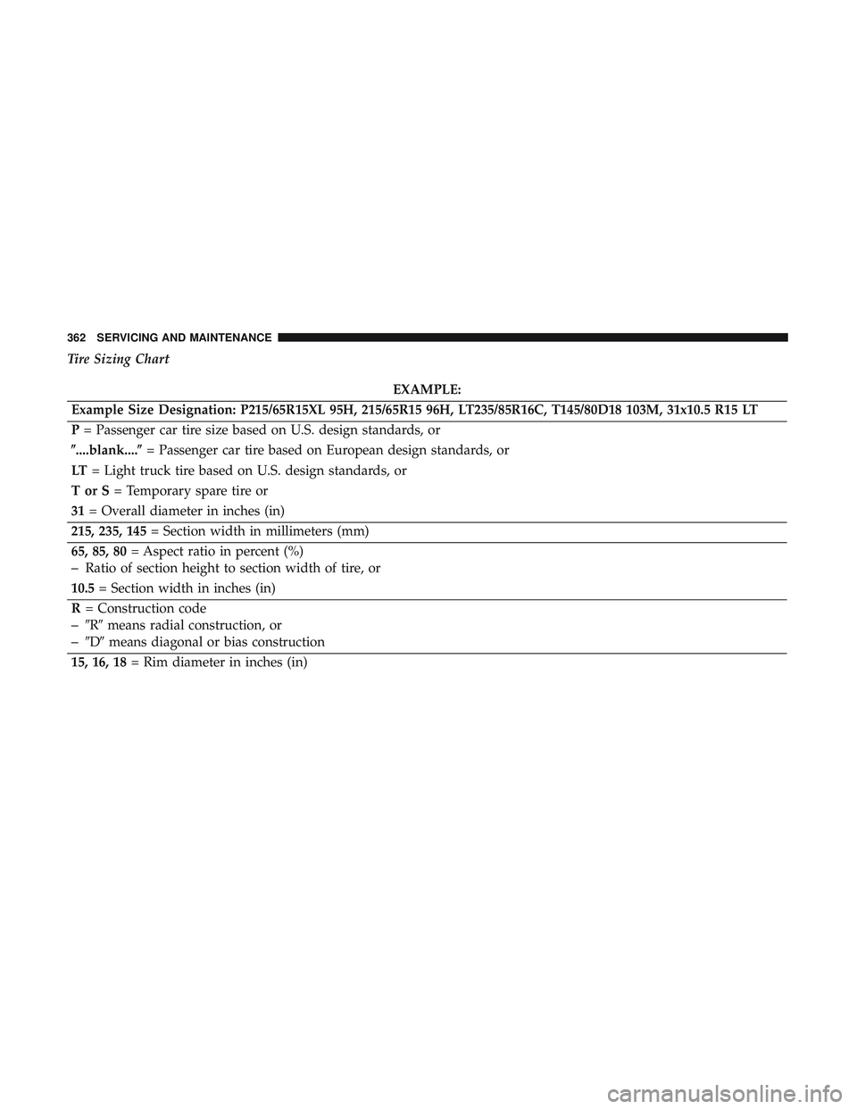
Tire Sizing Chart
EXAMPLE:
Example Size Designation: P215/65R15XL 95H, 215/65R15 96H, LT235/85R16C, T145/80D18 103M, 31x10.5 R15 LT
P = Passenger car tire size based on U.S. design standards, or
�....blank....� = Passenger car tire based on European design standards, or
LT = Light truck tire based on U.S. design standards, or
TorS= Temporary spare tire or
31 = Overall diameter in inches (in)
215, 235, 145 = Section width in millimeters (mm)
65, 85, 80 = Aspect ratio in percent (%)
–Ratio of section height to section width of tire, or
10.5 = Section width in inches (in)
R = Construction code
–�R� means radial construction, or
–�D� means diagonal or bias construction
15, 16, 18 = Rim diameter in inches (in)
362 SERVICING AND MAINTENANCE
Page 413 of 500

Safety & Driving Assistance
After pressing the “Safety & Driving Assistance” button on the touchscreen, the following settings will be available:
Setting NameSelectable Options
ParkView Backup Camera Delay OnOff
NOTE:
The “ParkView Backup Camera Delay” setting determines whether or not the screen will display the rear view image
with dynamic grid lines for up to ten seconds after the vehicle is shifted out of REVERSE. This delay will be canceled
if the vehicle’s speed exceeds 8 mph (13 km/h), the transmission is shifted into PARK, or the ignition is switched to
the OFF position. Active ParkView Backup Camera Guide- lines On
Off
NOTE:
The “Active ParkView Backup Camera Guidelines” feature overlays the Rear Backup Camera image with active, or
dynamic, grid lines to help illustrate the width of the vehicle and its projected back up path, based on the steering
wheel position when the option is checked. A dashed center line overlay indicates the center of the vehicle to assist
with parking or aligning to a hitch/receiver.
10
MULTIMEDIA 411